EP0247496A2 - Vortriebsrohr - Google Patents
Vortriebsrohr Download PDFInfo
- Publication number
- EP0247496A2 EP0247496A2 EP87107250A EP87107250A EP0247496A2 EP 0247496 A2 EP0247496 A2 EP 0247496A2 EP 87107250 A EP87107250 A EP 87107250A EP 87107250 A EP87107250 A EP 87107250A EP 0247496 A2 EP0247496 A2 EP 0247496A2
- Authority
- EP
- European Patent Office
- Prior art keywords
- section
- jacking
- pipe
- jacking pipe
- pipe according
- Prior art date
- Legal status (The legal status is an assumption and is not a legal conclusion. Google has not performed a legal analysis and makes no representation as to the accuracy of the status listed.)
- Granted
Links
- 239000002184 metal Substances 0.000 claims abstract description 8
- 229910052751 metal Inorganic materials 0.000 claims abstract description 8
- 238000003825 pressing Methods 0.000 claims abstract description 8
- 238000000034 method Methods 0.000 claims abstract description 6
- 229910001141 Ductile iron Inorganic materials 0.000 claims description 5
- 238000009415 formwork Methods 0.000 claims description 5
- 238000005260 corrosion Methods 0.000 claims description 4
- 230000007797 corrosion Effects 0.000 claims description 4
- 230000000295 complement effect Effects 0.000 claims description 3
- 239000004567 concrete Substances 0.000 claims description 3
- 239000002689 soil Substances 0.000 description 4
- XEEYBQQBJWHFJM-UHFFFAOYSA-N Iron Chemical compound [Fe] XEEYBQQBJWHFJM-UHFFFAOYSA-N 0.000 description 2
- 238000010276 construction Methods 0.000 description 2
- 238000009413 insulation Methods 0.000 description 2
- 238000004519 manufacturing process Methods 0.000 description 2
- 239000000463 material Substances 0.000 description 2
- 238000007792 addition Methods 0.000 description 1
- 230000005540 biological transmission Effects 0.000 description 1
- 230000015572 biosynthetic process Effects 0.000 description 1
- 239000011248 coating agent Substances 0.000 description 1
- 238000000576 coating method Methods 0.000 description 1
- 238000005553 drilling Methods 0.000 description 1
- 230000000694 effects Effects 0.000 description 1
- 239000013013 elastic material Substances 0.000 description 1
- 238000010438 heat treatment Methods 0.000 description 1
- 239000011372 high-strength concrete Substances 0.000 description 1
- 229910052742 iron Inorganic materials 0.000 description 1
- 239000007788 liquid Substances 0.000 description 1
Images
Classifications
-
- E—FIXED CONSTRUCTIONS
- E21—EARTH OR ROCK DRILLING; MINING
- E21D—SHAFTS; TUNNELS; GALLERIES; LARGE UNDERGROUND CHAMBERS
- E21D9/00—Tunnels or galleries, with or without linings; Methods or apparatus for making thereof; Layout of tunnels or galleries
- E21D9/005—Tunnels or galleries, with or without linings; Methods or apparatus for making thereof; Layout of tunnels or galleries by forcing prefabricated elements through the ground, e.g. by pushing lining from an access pit
-
- E—FIXED CONSTRUCTIONS
- E21—EARTH OR ROCK DRILLING; MINING
- E21B—EARTH OR ROCK DRILLING; OBTAINING OIL, GAS, WATER, SOLUBLE OR MELTABLE MATERIALS OR A SLURRY OF MINERALS FROM WELLS
- E21B17/00—Drilling rods or pipes; Flexible drill strings; Kellies; Drill collars; Sucker rods; Cables; Casings; Tubings
-
- E—FIXED CONSTRUCTIONS
- E21—EARTH OR ROCK DRILLING; MINING
- E21B—EARTH OR ROCK DRILLING; OBTAINING OIL, GAS, WATER, SOLUBLE OR MELTABLE MATERIALS OR A SLURRY OF MINERALS FROM WELLS
- E21B17/00—Drilling rods or pipes; Flexible drill strings; Kellies; Drill collars; Sucker rods; Cables; Casings; Tubings
- E21B17/02—Couplings; joints
- E21B17/08—Casing joints
-
- E—FIXED CONSTRUCTIONS
- E21—EARTH OR ROCK DRILLING; MINING
- E21B—EARTH OR ROCK DRILLING; OBTAINING OIL, GAS, WATER, SOLUBLE OR MELTABLE MATERIALS OR A SLURRY OF MINERALS FROM WELLS
- E21B7/00—Special methods or apparatus for drilling
- E21B7/20—Driving or forcing casings or pipes into boreholes, e.g. sinking; Simultaneously drilling and casing boreholes
-
- F—MECHANICAL ENGINEERING; LIGHTING; HEATING; WEAPONS; BLASTING
- F16—ENGINEERING ELEMENTS AND UNITS; GENERAL MEASURES FOR PRODUCING AND MAINTAINING EFFECTIVE FUNCTIONING OF MACHINES OR INSTALLATIONS; THERMAL INSULATION IN GENERAL
- F16L—PIPES; JOINTS OR FITTINGS FOR PIPES; SUPPORTS FOR PIPES, CABLES OR PROTECTIVE TUBING; MEANS FOR THERMAL INSULATION IN GENERAL
- F16L58/00—Protection of pipes or pipe fittings against corrosion or incrustation
- F16L58/02—Protection of pipes or pipe fittings against corrosion or incrustation by means of internal or external coatings
- F16L58/04—Coatings characterised by the materials used
- F16L58/10—Coatings characterised by the materials used by rubber or plastics
- F16L58/1009—Coatings characterised by the materials used by rubber or plastics the coating being placed inside the pipe
-
- F—MECHANICAL ENGINEERING; LIGHTING; HEATING; WEAPONS; BLASTING
- F16—ENGINEERING ELEMENTS AND UNITS; GENERAL MEASURES FOR PRODUCING AND MAINTAINING EFFECTIVE FUNCTIONING OF MACHINES OR INSTALLATIONS; THERMAL INSULATION IN GENERAL
- F16L—PIPES; JOINTS OR FITTINGS FOR PIPES; SUPPORTS FOR PIPES, CABLES OR PROTECTIVE TUBING; MEANS FOR THERMAL INSULATION IN GENERAL
- F16L58/00—Protection of pipes or pipe fittings against corrosion or incrustation
- F16L58/02—Protection of pipes or pipe fittings against corrosion or incrustation by means of internal or external coatings
- F16L58/04—Coatings characterised by the materials used
- F16L58/10—Coatings characterised by the materials used by rubber or plastics
- F16L58/1054—Coatings characterised by the materials used by rubber or plastics the coating being placed outside the pipe
-
- F—MECHANICAL ENGINEERING; LIGHTING; HEATING; WEAPONS; BLASTING
- F16—ENGINEERING ELEMENTS AND UNITS; GENERAL MEASURES FOR PRODUCING AND MAINTAINING EFFECTIVE FUNCTIONING OF MACHINES OR INSTALLATIONS; THERMAL INSULATION IN GENERAL
- F16L—PIPES; JOINTS OR FITTINGS FOR PIPES; SUPPORTS FOR PIPES, CABLES OR PROTECTIVE TUBING; MEANS FOR THERMAL INSULATION IN GENERAL
- F16L9/00—Rigid pipes
- F16L9/14—Compound tubes, i.e. made of materials not wholly covered by any one of the preceding groups
- F16L9/153—Compound tubes, i.e. made of materials not wholly covered by any one of the preceding groups comprising only layers of metal and concrete with or without reinforcement
Definitions
- the invention relates to a jacking pipe for laying in the ground by means of a pressing process, with an inner pipe section made of metal and a sheathing section surrounding it.
- Such jacking pipes are known, wherein the casing section consists of a high-strength concrete, via which the forces required for feeding in the ground are transmitted to the parts of the pressing device which are arranged in front of the jacking pipe and loosen the ground in order to enable the jacking pipe to be driven.
- the inner tube section consisting of metal essentially serves only as an inner “coating” of the sheathing section which transmits the forces, in order in this way to achieve a reliable seal against leakage of liquid or gas through the sheathing section and to increase the compressive strength.
- Metal pipes can also be used as jacking pipes, but difficulties always arise if these metal pipes are not assembled without the formation of projections or shoulders.
- Existing projections or shoulders on the outer circumference of the pipe string composed of a plurality of jacking pipes hinder the feed because they come into engagement with the adjacent soil. Neither can be avoided by "drilling" the soil with a larger diameter than would be necessary taking into account the maximum diameter of the pipe string by means of the scraper head belonging to the pressing device. Then a cavity is formed around the pipe string that has been laid, into which the soil penetrates in a setting process, so that subsidence can occur on the surface of the earth.
- a jacking pipe of the type mentioned at the outset is designed according to the invention in such a way that the inner pipe section is designed to transmit the driving force and that the casing section ends at a distance from at least one end of the jacking pipe.
- the inner pipe section consists of standard ductile cast iron pipes, and these can have complementary parts of a connecting sleeve at their ends.
- the jacking pipe according to the invention is therefore constructed in exactly the opposite manner to the known jacking pipe described above, in that the inner pipe section made of metal serves to transmit the jacking force, while the casing section does not transmit any jacking forces because it is at a distance from at least one end of the jacking pipe ends, so that when several jacking pipes are joined together to form a pipe string an annular gap is present between the jacketing sections of adjacent jacking pipes, ie the jacketing sections of adjacent jacking pipes do not touch.
- the diameter of the sheathing section can be precisely adapted to the dimensions of the scraper head used in the pressing device, so that the jacking pipe completely fills the hole produced, ie no soil can sink into this hole when the jacking pipe is inserted. Furthermore, a completely smooth outer surface can be formed without projections, so that when using ductile iron pipes with complementary parts of an optionally pressure-tight connecting sleeve present at their ends, a complete covering or covering of these connecting sleeve parts can be achieved if only the outer diameter of the casing is formed correspondingly larger than the maximum diameter of the connecting sleeve parts.
- the casing section of the jacking pipe according to the invention can, for example, consist of concrete, which can have very low strength because it is ensured that it does not contribute to the transmission of jacking forces.
- the sheathing section from foamed plastic, which is particularly expedient when a heat insulation effect is desired, for example in district heating pipes.
- the casing section is usually produced by means of a formwork in the form of a cylindrical casing which is arranged to form an annular space around the inner tube section, so that the material for the casing section can then be introduced into this annular space in order to harden there.
- this formwork is not removed, so that the casing section remains surrounded by the casing previously used as formwork.
- the inner surface of the inner pipe section can be covered with a corrosion protection layer or the pipe section can consist of corrosion-resistant material.
- the section of a pipe run shown in FIG. 1 consists of three jacking pipes of the same construction. These three jacking pipes are identified by the same reference numerals, which differ only in the additions ⁇ and ⁇ . Therefore only the middle jacking pipe is described.
- the jacking pipe shown has an inner pipe section 1 in the form of a ductile cast iron pipe which has an overlapping part 3 for a connecting sleeve at its left end and a correspondingly shaped part 4 for a connecting sleeve at its right end.
- the part 3 of the connecting sleeve is in engagement with the part 4 ⁇ of the adjacent jacking pipe corresponding to the part 4, while the part 4m of the connecting sleeve is overlapped by the part 3 ⁇ of the right adjacent jacking pipe and is in engagement therewith.
- the inner pipe section 1 is surrounded by a casing section 2, the maximum diameter of which is larger than the maximum diameter of the connecting sleeve part 3, so that the casing section 2 forms a continuous, smooth cylindrical outer surface.
- the sheathing section 2 extends to the end of the inner pipe section 1, ie it closes with the end of the connecting sleeve part 3, while it ends at the right end at a clear distance from the end of the inner pipe section 1.
- the casing sections 2, 2 ⁇ , 2 ⁇ can consist, for example, of low-strength concrete or of foamed plastic, and the annular gaps 5 can optionally be filled with a permanently elastic material, in particular if the casing section 2, 2 ⁇ , 2 ⁇ is to be used for thermal insulation .
- the inner wall of the inner pipe section 1 is covered with a corrosion protection layer 6, so that even aggressive media can be passed through the pipe string.
- the jacking pipe according to FIG. 2 has a jacket 17 which was previously used as formwork for the production of the jacket section 12 on the inner pipe section 11.
- the jacket 17 can for example consist of PVC or have the shape of a thin metal tube.
Landscapes
- Engineering & Computer Science (AREA)
- General Engineering & Computer Science (AREA)
- Mining & Mineral Resources (AREA)
- Life Sciences & Earth Sciences (AREA)
- Mechanical Engineering (AREA)
- Geology (AREA)
- Environmental & Geological Engineering (AREA)
- General Life Sciences & Earth Sciences (AREA)
- Geochemistry & Mineralogy (AREA)
- Fluid Mechanics (AREA)
- Physics & Mathematics (AREA)
- Rigid Pipes And Flexible Pipes (AREA)
- Excavating Of Shafts Or Tunnels (AREA)
- Electrical Discharge Machining, Electrochemical Machining, And Combined Machining (AREA)
- Joints With Sleeves (AREA)
- Valve Device For Special Equipments (AREA)
Abstract
Description
- Die Erfindung bezieht sich auf ein Vortriebsrohr zur Verlegung im Boden mittels eines Preßverfahrens, mit einem aus Metall bestehenden inneren Rohrabschnitt und einem diesen umgebenden Ummantelungsabschnitt.
- Derartige Vortriebsrohre sind bekannt, wobei der Ummantelungsabschnitt aus einem hochfesten Beton besteht, über den die zum Vorschub im Boden erforderlichen Kräfte auf die Teile der Preßvorrichtung übertragen werden, die vor dem Vortriebsrohr angeordnet sind und den Boden lösen, um den Vortrieb des Vortriebsrohres zu ermöglichen. Der aus Metall bestehende innere Rohrabschnitt dient im wesentlichen nur als innere "Beschichtung" des die Kräfte übertragenden Ummantelungsabschnittes, um auf diese Weise eine zuverlässige Abdichtung gegen Austritt von Flüssigkeit oder Gas durch den Ummantelungsabschnitt nach außen zu erreichen sowie die Druckfestigkeit zu erhöhen.
- An sich lassen sich als Vortriebsrohre auch Metallrohre verwenden, doch ergeben sich dann immer wieder Schwierigkeiten, wenn diese Metallrohre nicht ohne Bildung von Vorsprüngen oder Absätzen zusammengesetzt werden. Vorhandene Vorsprünge oder Absätze am äußeren Umfang des aus mehreren Vortriebsrohren zusammengesetzten Rohrstranges behindern nämlich den Vorschub, weil sie in Eingriff mit dem benachbarten Erdreich kommen. Dies kann auch nicht dadurch vermieden werden daß man mittels des zu Preßvorrichtung gehörenden Schürfkopfes das Erdreich mit größerem Durchmesser "aufbohrt" als an sich unter Berücksichtigung des maximalen Durchmessers des Rohrstranges erforderlich wäre. Dann bildet sich nämlich um den verlegten Rohrstrang ein Hohlraum, in den das Erdreich in einem Setzvorgang nachdringt, so daß an der Erdoberfläche Senkungen auftreten können.
- Es ist Aufgabe der Erfindung, ein Vortriebsrohr zu schaffen, das bei großer Druckfestigkeit einfach herstellbar ist und den beim Preßvorgang entstehenden Raum im Erdreich vollständig ausfüllt.
- Zur Lösung dieser Aufgabe wird ein Vortriebsrohr der eingangs erwähnten Art erfindungsgemäß derart ausgestaltet, daß der innere Rohrabschnitt zur Übertragung der Vortriebskraft ausgebildet ist und daß der Ummantelungsabschnitt im Abstand von zumindest einem Ende des Vortriebsrohres endet. Vorzugsweise besteht dabei der innere Rohrabschnitt aus duktilen Standard-Gußrohren, und diese können an ihren Enden einander ergänzende Teile einer Verbindungsmuffe aufweisen.
- Das erfindunsgemäße Vortriebsrohr ist also, verglichen mit dem vorstehend beschriebenen, bekannten Vortriebsrohr, genau umgekehrt aufgebaut, indem der innere, aus Metall bestehende Rohrabschnitt zur Übertragung der Vortriebskraft dient, während der Ummantelungsabschnitt keinerlei Vortriebskräfte überträgt, weil er im Abstand von zumindest einem Ende des Vortriebsrohres endet, so daß beim Zusammenfügen mehrerer Vortriebsrohre zu einem Rohrstrang zwischen den Ummantelungsabschnitten benachbarter Vortriebsrohre ein Ringspalt vorhanden ist, d.h. die Ummantelungsabschnitte benachbarter Vortriebsrohre berühren sich nicht.
- Der Ummantelungsabschnitt kann in seinem Durchmesser genau in Anpassung an die Abmessungen des in der Preßvorrichtung verwendeten Schürfkopfes ausgebildet sein, so daß das Vortriebsrohr die hergestellte Bohrung vollständig ausfüllt, also kein Erdreich in diese Bohrung nachsinken kann, wenn das Vortriebsrohr eingebracht ist. Ferner läßt sich eine vollständig glatte Außenfläche ohne Vorsprünge bilden, so daß bei Verwendung von duktilen Gußrohren mit an ihren Enden vorhandenen, einander ergänzenden Teilen einer gegebenenfalls druckdichten Verbindungsmuffe eine vollständige Abdeckung bzw. Überdeckung dieser Verbindungsmuffenteile erreicht werden kann, wenn nur der äußere Durchmesser der Ummantelung entsprechend größer als der maximale Durchmesser der Verbindungsmuffenteile ausgebildet wird.
- Auf diese Weise wird es zum ersten Mal möglich, duktile Gußrohre, ( Gußrohre, die durch eine besondere Gefügestruktur ihre Sprödigkeit verloren haben), wie sie als Standard-Produkt erhältlich sind, als Vortriebsrohre zur Verlegung im Boden mittels eines Preßverfahrens einzusetzen, was bisher wegen der vorspringenden Verbindungsmuffenteile nicht möglich war.
- Der Ummantelungsabschnitt des erfindungsgemäßen Vortriebsrohres kann beispielsweise aus Beton bestehen, wobei dieser sehr geringe Festigkeit haben kann, weil sichergestellt ist, daß er nicht zur Übertragung von Vortriebskräften beiträgt.
- Es ist auch möglich, den Ummantelungsabschnitt aus geschäumtem Kunststoff herzustellen, was inbesondere dann zweckmäßig ist, wenn eine Wärmeisolierwirkung erwünscht ist, etwa bei Fernwärmeleitungen.
- Üblicherweise wird der Ummantelungsabschnitt mittels einer Schalung in Form eines zylindrischen Mantels hergestellt, der einen Ringraum um den inneren Rohrabschnitt bildend angeordnet wird, so daß das Material für den Ummantelungsabschnitt dann in diesen Ringraum eingebracht werden kann, um dort auszuhärten.
- In einer Weiterbildung des erfindungsgemäßen Vortriebsrohres wird diese Schalung nicht entfernt, so daß der Ummantelungsabschnitt von dem zuvor als Schalung verwendeten Mantel umgeben bleibt.
- Die Innenfläche des inneren Rohrabschnittes kann mit einer Korrosionsschutzschicht bedeckt sein oder der Rohrabschnitt kann aus korrosionsfestem Material bestehen.
- Die Erfindung wird im folgenden anhand der schematisch Ausführungsbeispiele zeigenden Figuren näher erläutert.
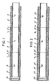
- Figur 1 zeigt im Schnitt ein Stück eines Rohrstranges aus Vortriebsrohren.
- Figur 2 zeigt in einer Darstellung entsprechend Figur 1 Vortriebsrohre mit einem den Ummantelungsabschnitt umgebenden Mantel.
- Der in Figur 1 dargestellte Abschnitt eines Rohrstranges besteht aus drei gleich aufgebauten Vortriebsrohren. Diese drei Vortriebsrohre sind mit gleichen Bezugszeichen bezeichnet, die sich lediglich durch die Zusätze ʹ und ʺ unterscheiden. Es wird daher nur das mittlere Vortriebsrohr beschrieben.
- Das dargestellte Vortriebsrohr hat einen inneren Rohrabschnitt 1 in Form eines duktilen Gußrohres, das an seinem linken Ende ein übergreifendes Teil 3 für eine Verbindungsmuffe und an seinem rechten Ende ein entsprechend geformtes Teil 4 für eine Verbindungsmuffe aufweist. Wie dargestellt, steht das Teil 3 der Verbindungsmuffe in Eingriff mit dem dem Teil 4 entsprechenden Teil 4ʺ des benachbarten Vortriebsrohres, während das Teil 4 der Verbindungsmuffe vom Teil 3ʹ des rechten benachbarten Vortriebsrohres übergriffen wird und mit diesem in Eingriff steht.
- Der innere Rohrabschnitt 1 ist von einem Ummantelungsabschnitt 2 umgeben, dessen maximaler Durchmesser größer ist als der maximale Durchmesser des Verbindungsmuffenteils 3, so daß der Ummantelungsabschnitt 2 eine durchgehende, glatte zylindrische Außenfläche bildet. Am in Figur 1 linken Ende erstreckt sich der Ummantelungsabschnitt 2 bis zum Ende des inneren Rohrabschnittes 1, d.h. er schließt mit dem Ende des Verbindungsmuffenteils 3 ab, während er am rechten Ende in deutlichem Abstand vom Ende des inneren Rohrabschnittes 1 endet. Dadurch ergibt sich, wie dargestellt, im montierten Zustand zwischen dem in Figur 1 jeweils rechten Ende eines Ummantelungsabschnittes und dem linken Ende des Ummantelungsabschnittes des benachbarten Vortriebsrohres ein Ringspalt 5, d.h. das rechte Ende eines Ummantelungsabschnittes 2 endet bei zum Rohrstrang verbundenen Vortriebsrohren im Abstand vom linken Ende des benachbarten Vortriebsrohres. Auf diese Weise ist sichergestellt, daß über die Ummantelungsabschnitte 2ʹ, 2, 2ʺ des gebildeten Rohrstranges keine Vortriebskräfte übertragen werden können.
- Wie vorstehend bereits erwähnt, können die Ummantelungsabschnitte 2, 2ʹ, 2ʺ beispielsweise aus Beton geringer Festigkeit oder aus geschäumtem Kunststoff bestehen, und die Ringspalte 5 können gegebenenfalls mit einem dauerelastischen Material verfüllt werden, insbesondere wenn der Ummantelungsabschnitt 2, 2ʹ, 2ʺ zur Wärmeisolierung dienen soll.
- Wie dargestellt, ist die Innenwand des inneren Rohrabschnittes 1 mit einer Korrosionsschutzschicht 6 bedeckt, so daß auch aggressive Medien durch den Rohrstrang geleitet werden können.
- Die zu einem Teil eines Rohrstranges zusammengesetzten Vortriebsrohre gemäß Figur 2 stimmen in ihrem Aufbau mit dem Vortriebsrohr gemäß Figur 1 überein, und gleiche Teile sind mit um jeweils 10 erhöhten Bezugszeichen bezeichnet.
- Zusätzlich weist das Vortriebsrohr gemäß Figur 2 jedoch einen Mantel 17 auf, der zuvor als Schalung für die Herstellung des Ummantelungsabschnittes 12 auf dem inneren Rohrabschnitt 11 verwendet wurde. Der Mantel 17 kann beispielsweise aus PVC bestehen oder die Form eines dünnen Metallrohres haben.
Claims (9)
Priority Applications (1)
| Application Number | Priority Date | Filing Date | Title |
|---|---|---|---|
| AT87107250T ATE66717T1 (de) | 1986-05-30 | 1987-05-19 | Vortriebsrohr. |
Applications Claiming Priority (2)
| Application Number | Priority Date | Filing Date | Title |
|---|---|---|---|
| DE3618334A DE3618334C1 (de) | 1986-05-30 | 1986-05-30 | Vortriebsrohr |
| DE3618334 | 1986-05-30 |
Publications (3)
| Publication Number | Publication Date |
|---|---|
| EP0247496A2 true EP0247496A2 (de) | 1987-12-02 |
| EP0247496A3 EP0247496A3 (en) | 1988-12-21 |
| EP0247496B1 EP0247496B1 (de) | 1991-08-28 |
Family
ID=6302026
Family Applications (1)
| Application Number | Title | Priority Date | Filing Date |
|---|---|---|---|
| EP87107250A Expired - Lifetime EP0247496B1 (de) | 1986-05-30 | 1987-05-19 | Vortriebsrohr |
Country Status (4)
| Country | Link |
|---|---|
| US (1) | US4808032A (de) |
| EP (1) | EP0247496B1 (de) |
| AT (1) | ATE66717T1 (de) |
| DE (2) | DE3618334C1 (de) |
Cited By (4)
| Publication number | Priority date | Publication date | Assignee | Title |
|---|---|---|---|---|
| GB2213554A (en) * | 1987-12-09 | 1989-08-16 | Kurimoto Ltd | Low load pipe for pipe jacking |
| EP0439313A3 (en) * | 1990-01-25 | 1992-05-06 | Stanton Plc | Pipe joints and couplings and parts thereof |
| WO1993006403A1 (de) * | 1991-09-27 | 1993-04-01 | Buderus Guss Gmbh | Vortriebsrohr zum unterirdischen vortrieb |
| EP0611875A1 (de) * | 1993-02-19 | 1994-08-24 | Pont-A-Mousson S.A. | Rohrvortriebsstrang und entsprechendes Vortriebsrohr |
Families Citing this family (22)
| Publication number | Priority date | Publication date | Assignee | Title |
|---|---|---|---|---|
| DE8710143U1 (de) * | 1987-07-24 | 1987-09-10 | Bohrtec GmbH & Co KG für Bohrtechnologie, 5100 Aachen | Vorpreßrohr |
| DE3823331A1 (de) * | 1988-07-09 | 1990-01-11 | Schmidt Paul | Verfahren und vorrichtung zum einrammen von rohren |
| DE3837161A1 (de) * | 1988-11-02 | 1990-05-03 | Buderus Bau & Abwassertechnik | Vortriebsrohr zum vortrieb aus vertikalen schaechten |
| DE3922985A1 (de) * | 1989-07-12 | 1991-01-17 | Halbergerhuette Gmbh | Rohrverbindung fuer vortriebsrohre, die in vortriebstechnik unterirdisch verlegt werden |
| DE9106846U1 (de) * | 1991-06-04 | 1991-08-22 | Thyssen Industrie Ag, 4300 Essen | Vortriebsrohr aus duktilem Gußeisen |
| DE4243353C2 (de) * | 1992-12-21 | 1997-07-03 | Halbergerhuette Gmbh | Vortriebsrohrverbindung für den unterirdischen Schildvortrieb |
| EP0639690A4 (de) * | 1993-03-05 | 1997-04-09 | Kawasaki Steel Co | Doppelwandiges rohr für die bohrtechnik und ausführung des rohrmundstücks. |
| US5662432A (en) * | 1995-03-27 | 1997-09-02 | Cook Construction Company, Inc. | Pipe insertion machine and method |
| DE19745130A1 (de) * | 1997-10-13 | 1999-04-15 | Ruhrgas Ag | Verfahren zum Verlegen einer Leitung sowie Leitung mit einem Mantelrohr und einem Produktrohr |
| DE19860259B4 (de) * | 1998-12-24 | 2006-05-11 | Gildemeister Tief-, Stahlbeton- U. Rohrleitungsbau Gmbh & Co. Kg | Vortriebsrohrleitung |
| GB0106378D0 (en) * | 2001-03-15 | 2001-05-02 | Sps Afos Group Ltd | Apparatus and method for running downhole liners |
| DE10202261A1 (de) * | 2002-01-21 | 2003-08-07 | Waterkotte Waermepumpen Gmbh | Wärmequellen- oder Wärmesenken-Anlage mit thermischer Erdankopplung |
| AT412572B (de) | 2003-11-18 | 2005-04-25 | Woltron Herbert Dipl Ing | Vortriebsrohr zur verlegung im boden |
| US7363769B2 (en) | 2005-03-09 | 2008-04-29 | Kelix Heat Transfer Systems, Llc | Electromagnetic signal transmission/reception tower and accompanying base station employing system of coaxial-flow heat exchanging structures installed in well bores to thermally control the environment housing electronic equipment within the base station |
| CN101311598B (zh) * | 2007-05-24 | 2011-08-17 | 天津万联管道工程有限公司 | 钢筒加强钢制承插口预应力混凝土顶管 |
| US7757718B1 (en) * | 2007-06-20 | 2010-07-20 | Bruce Mark H | Polymer reinforcement for a clay pipe joint |
| CN102777706A (zh) * | 2012-08-10 | 2012-11-14 | 新兴铸管股份有限公司 | 外包混凝土球墨铸铁管 |
| CN102889441A (zh) * | 2012-10-15 | 2013-01-23 | 三河京龙新型管道有限责任公司 | 热力顶进施工用钢筋混凝土套管 |
| US9200732B2 (en) * | 2012-12-31 | 2015-12-01 | North American Specialty Products Llc | Flush joint pipe |
| US10370967B2 (en) * | 2014-09-10 | 2019-08-06 | Mekorot Water Company, Ltd. | Integrated jacking pipes |
| CN104482320B (zh) * | 2014-11-21 | 2017-01-18 | 湖南振辉管业有限公司 | 一种多功能球墨铸铁管 |
| CA3244725C (en) * | 2024-06-28 | 2026-06-02 | Technical Construction Infrastructure Inc. | Method for refurbishing pre-stressed concrete cylinder pipe and refurbished pre-stressed concrete cylinder pipe |
Family Cites Families (12)
| Publication number | Priority date | Publication date | Assignee | Title |
|---|---|---|---|---|
| US1770180A (en) * | 1926-03-18 | 1930-07-08 | Lock Joint Pipe Co | Pipe and method of making it |
| US1847814A (en) * | 1931-04-06 | 1932-03-01 | Jr Thomas Byrne | Caisson construction |
| US2348477A (en) * | 1942-07-31 | 1944-05-09 | American Pipe & Constr Co | Pipe and method of making same |
| US2662555A (en) * | 1948-12-03 | 1953-12-15 | Lock Joint Pipe Co | Pipe and method for making the same |
| US3352120A (en) * | 1965-09-15 | 1967-11-14 | Grace L Pelzer | Reinforced concrete pile |
| DE1231190B (de) * | 1965-10-22 | 1966-12-29 | Wilhelm Tenten G M B H | Aus einzelnen Rohrschuessen bestehender Rohrstrang zum Verrohren von mit Fluessigkeit gefuellten Bohrloechern od. dgl. |
| DE1625936C3 (de) * | 1967-09-29 | 1978-04-06 | Benteler-Werke Ag Werk Neuhaus, 4794 Schloss Neuhaus | Durch Biegen verformbares Leitungsrohr aus Metall für Heizungsanlagen und Wasserinstallationen, insbesondere Warmwasserleitungen |
| US3825037A (en) * | 1972-04-05 | 1974-07-23 | Price Brothers Co | Jacking pipe |
| GB1443940A (en) * | 1972-12-04 | 1976-07-28 | British Petroleum Co | Piping |
| AT357946B (de) * | 1973-10-30 | 1980-08-11 | Aumann Keller & Pichler Kg Bau | Vorrichtung zum vortrieb eines aus mindestens einem rohrabschnitt bestehenden rohres im erdboden |
| SE458863B (sv) * | 1979-12-19 | 1989-05-16 | Gustavsberg Ab | Paalkonstruktion |
| DE3142177A1 (de) * | 1981-10-23 | 1983-05-11 | Schlegel Lining Technology GmbH, 2000 Hamburg | "betonrohr mit einr polymeren auskleidung" |
-
1986
- 1986-05-30 DE DE3618334A patent/DE3618334C1/de not_active Expired
-
1987
- 1987-05-19 AT AT87107250T patent/ATE66717T1/de not_active IP Right Cessation
- 1987-05-19 DE DE8787107250T patent/DE3772452D1/de not_active Expired - Fee Related
- 1987-05-19 EP EP87107250A patent/EP0247496B1/de not_active Expired - Lifetime
- 1987-05-29 US US07/055,217 patent/US4808032A/en not_active Expired - Fee Related
Cited By (7)
| Publication number | Priority date | Publication date | Assignee | Title |
|---|---|---|---|---|
| GB2213554A (en) * | 1987-12-09 | 1989-08-16 | Kurimoto Ltd | Low load pipe for pipe jacking |
| US4966494A (en) * | 1987-12-09 | 1990-10-30 | Kurimoto Ltd. | Low load pipe for pipe jacking |
| GB2213554B (en) * | 1987-12-09 | 1991-09-04 | Kurimoto Ltd | Low load pipe for pipe jacking |
| EP0439313A3 (en) * | 1990-01-25 | 1992-05-06 | Stanton Plc | Pipe joints and couplings and parts thereof |
| WO1993006403A1 (de) * | 1991-09-27 | 1993-04-01 | Buderus Guss Gmbh | Vortriebsrohr zum unterirdischen vortrieb |
| EP0611875A1 (de) * | 1993-02-19 | 1994-08-24 | Pont-A-Mousson S.A. | Rohrvortriebsstrang und entsprechendes Vortriebsrohr |
| FR2701750A1 (fr) * | 1993-02-19 | 1994-08-26 | Pont A Mousson | Ligne de tuyaux de fonçage, et tuyau de fonçage correspondant. |
Also Published As
| Publication number | Publication date |
|---|---|
| US4808032A (en) | 1989-02-28 |
| EP0247496B1 (de) | 1991-08-28 |
| EP0247496A3 (en) | 1988-12-21 |
| ATE66717T1 (de) | 1991-09-15 |
| DE3772452D1 (de) | 1991-10-02 |
| DE3618334C1 (de) | 1987-07-02 |
Similar Documents
| Publication | Publication Date | Title |
|---|---|---|
| EP0247496B1 (de) | Vortriebsrohr | |
| DE1525678A1 (de) | Waermeisoliertes Rohr und Verfahren zu seiner Herstellung | |
| EP0044468B1 (de) | Wärmeisoliertes Rohrleitungselement und Rohrleitungssystem aus diesen Rohrleitungselementen sowie Verfahren zur Herstellung des Rohrleitungselementes und des Rohrleitungssystems | |
| DE2804208A1 (de) | Feuerbestaendige durchfuehrung und verfahren zur herstellung derselben | |
| DE102015204926A1 (de) | Umhüllung einer Mantelfläche eines Rohrs | |
| DE1285801B (de) | Im Erdreich zu verlegendes Verbundrohr | |
| DE2743639A1 (de) | Mit flexiblem stab armierte betonstuetze und verfahren zur herstellung derselben | |
| DE3541896A1 (de) | Verfahren zur zug- und druckfesten stoss-verbindung von betonrippenstahl mit hilfe einer rohrmuffe | |
| DE3245462C2 (de) | ||
| CH679786A5 (de) | ||
| DE3302075C2 (de) | Verbindung für Spannbeton- oder Stahlbetonbiegeträger | |
| DE2838363A1 (de) | Fluessigkeitsundurchlaessige wandung und verfahren zur herstellung derselben | |
| DE102012110226A1 (de) | Verpressschlauch zum Abdichten von Arbeitsfugen zwischen Bauwerksteilen | |
| DE3428549A1 (de) | Manschettenrohr fuer die bodenverfestigung im injektionsverfahren | |
| DE3524865C2 (de) | ||
| DE102006031832A1 (de) | Bauteil und ein Verfahren zur Herstellung eines Bauteils | |
| DE2100528A1 (de) | Hitzebeständiges Rohr | |
| DE69406816T2 (de) | Rohrvortriebsstrang und entsprechendes Vortriebsrohr | |
| DE7824988U1 (de) | Rohr fuer abwasserkanaele | |
| DE2630459A1 (de) | Unterirdisch zu verlegendes, von einem erhitzten medium durchstroembares leitungs-, insbesondere fernheizleitungsrohr und verfahren zu seiner herstellung | |
| DE872479C (de) | Rohrbrunnenfilter aus nichtmetallischen Baustoffen, insbesondere Steinzeug | |
| DE2247473C3 (de) | Verbindungskonstruktion für übereinander angeordnete Betonfertigteile | |
| DE2546800A1 (de) | Kanalisations-einsteigeschacht | |
| DE1479923A1 (de) | Verfahren zum Herstellen von mit einer Waermeisolierung versehenen Verbundrohren,insbesondere fuer Fernheizleitungen | |
| DE973499C (de) | Verfahren und Vorrichtung zum Anschluss von Rauchrohren an aus Formsteinen aufgemauerte Kamine |
Legal Events
| Date | Code | Title | Description |
|---|---|---|---|
| PUAI | Public reference made under article 153(3) epc to a published international application that has entered the european phase |
Free format text: ORIGINAL CODE: 0009012 |
|
| AK | Designated contracting states |
Kind code of ref document: A2 Designated state(s): AT BE CH DE FR GB IT LI LU NL |
|
| PUAL | Search report despatched |
Free format text: ORIGINAL CODE: 0009013 |
|
| AK | Designated contracting states |
Kind code of ref document: A3 Designated state(s): AT BE CH DE FR GB IT LI LU NL |
|
| 17P | Request for examination filed |
Effective date: 19890107 |
|
| 17Q | First examination report despatched |
Effective date: 19891019 |
|
| GRAA | (expected) grant |
Free format text: ORIGINAL CODE: 0009210 |
|
| AK | Designated contracting states |
Kind code of ref document: B1 Designated state(s): AT BE CH DE FR GB IT LI LU NL |
|
| REF | Corresponds to: |
Ref document number: 66717 Country of ref document: AT Date of ref document: 19910915 Kind code of ref document: T |
|
| ITF | It: translation for a ep patent filed | ||
| GBT | Gb: translation of ep patent filed (gb section 77(6)(a)/1977) | ||
| REF | Corresponds to: |
Ref document number: 3772452 Country of ref document: DE Date of ref document: 19911002 |
|
| ET | Fr: translation filed | ||
| PLBE | No opposition filed within time limit |
Free format text: ORIGINAL CODE: 0009261 |
|
| STAA | Information on the status of an ep patent application or granted ep patent |
Free format text: STATUS: NO OPPOSITION FILED WITHIN TIME LIMIT |
|
| 26N | No opposition filed | ||
| EPTA | Lu: last paid annual fee | ||
| PGFP | Annual fee paid to national office [announced via postgrant information from national office to epo] |
Ref country code: AT Payment date: 19980423 Year of fee payment: 12 |
|
| PGFP | Annual fee paid to national office [announced via postgrant information from national office to epo] |
Ref country code: BE Payment date: 19980512 Year of fee payment: 12 |
|
| PGFP | Annual fee paid to national office [announced via postgrant information from national office to epo] |
Ref country code: GB Payment date: 19980515 Year of fee payment: 12 |
|
| PGFP | Annual fee paid to national office [announced via postgrant information from national office to epo] |
Ref country code: CH Payment date: 19980520 Year of fee payment: 12 |
|
| PGFP | Annual fee paid to national office [announced via postgrant information from national office to epo] |
Ref country code: FR Payment date: 19980528 Year of fee payment: 12 |
|
| PGFP | Annual fee paid to national office [announced via postgrant information from national office to epo] |
Ref country code: NL Payment date: 19980531 Year of fee payment: 12 |
|
| PGFP | Annual fee paid to national office [announced via postgrant information from national office to epo] |
Ref country code: LU Payment date: 19980611 Year of fee payment: 12 |
|
| PGFP | Annual fee paid to national office [announced via postgrant information from national office to epo] |
Ref country code: DE Payment date: 19980717 Year of fee payment: 12 |
|
| PG25 | Lapsed in a contracting state [announced via postgrant information from national office to epo] |
Ref country code: LU Free format text: LAPSE BECAUSE OF NON-PAYMENT OF DUE FEES Effective date: 19990519 Ref country code: GB Free format text: LAPSE BECAUSE OF NON-PAYMENT OF DUE FEES Effective date: 19990519 Ref country code: AT Free format text: LAPSE BECAUSE OF NON-PAYMENT OF DUE FEES Effective date: 19990519 |
|
| PG25 | Lapsed in a contracting state [announced via postgrant information from national office to epo] |
Ref country code: LI Free format text: LAPSE BECAUSE OF NON-PAYMENT OF DUE FEES Effective date: 19990531 Ref country code: CH Free format text: LAPSE BECAUSE OF NON-PAYMENT OF DUE FEES Effective date: 19990531 Ref country code: BE Free format text: LAPSE BECAUSE OF NON-PAYMENT OF DUE FEES Effective date: 19990531 |
|
| BERE | Be: lapsed |
Owner name: MEYER & JOHN G.M.B.H. & CO TIEF- UND ROHRLEITUNGS Effective date: 19990531 |
|
| PG25 | Lapsed in a contracting state [announced via postgrant information from national office to epo] |
Ref country code: NL Free format text: LAPSE BECAUSE OF NON-PAYMENT OF DUE FEES Effective date: 19991201 |
|
| REG | Reference to a national code |
Ref country code: CH Ref legal event code: PL |
|
| GBPC | Gb: european patent ceased through non-payment of renewal fee |
Effective date: 19990519 |
|
| PG25 | Lapsed in a contracting state [announced via postgrant information from national office to epo] |
Ref country code: FR Free format text: LAPSE BECAUSE OF NON-PAYMENT OF DUE FEES Effective date: 20000131 |
|
| NLV4 | Nl: lapsed or anulled due to non-payment of the annual fee |
Effective date: 19991201 |
|
| PG25 | Lapsed in a contracting state [announced via postgrant information from national office to epo] |
Ref country code: DE Free format text: LAPSE BECAUSE OF NON-PAYMENT OF DUE FEES Effective date: 20000301 |
|
| REG | Reference to a national code |
Ref country code: FR Ref legal event code: ST |
|
| PG25 | Lapsed in a contracting state [announced via postgrant information from national office to epo] |
Ref country code: IT Free format text: LAPSE BECAUSE OF NON-PAYMENT OF DUE FEES;WARNING: LAPSES OF ITALIAN PATENTS WITH EFFECTIVE DATE BEFORE 2007 MAY HAVE OCCURRED AT ANY TIME BEFORE 2007. THE CORRECT EFFECTIVE DATE MAY BE DIFFERENT FROM THE ONE RECORDED. Effective date: 20050519 |