EP0247643A1 - Winkelstellungsdetektor - Google Patents
Winkelstellungsdetektor Download PDFInfo
- Publication number
- EP0247643A1 EP0247643A1 EP87200411A EP87200411A EP0247643A1 EP 0247643 A1 EP0247643 A1 EP 0247643A1 EP 87200411 A EP87200411 A EP 87200411A EP 87200411 A EP87200411 A EP 87200411A EP 0247643 A1 EP0247643 A1 EP 0247643A1
- Authority
- EP
- European Patent Office
- Prior art keywords
- dial
- significant
- reading
- value
- signal
- Prior art date
- Legal status (The legal status is an assumption and is not a legal conclusion. Google has not performed a legal analysis and makes no representation as to the accuracy of the status listed.)
- Withdrawn
Links
Images


Classifications
-
- G—PHYSICS
- G01—MEASURING; TESTING
- G01D—MEASURING NOT SPECIALLY ADAPTED FOR A SPECIFIC VARIABLE; ARRANGEMENTS FOR MEASURING TWO OR MORE VARIABLES NOT COVERED IN A SINGLE OTHER SUBCLASS; TARIFF METERING APPARATUS; MEASURING OR TESTING NOT OTHERWISE PROVIDED FOR
- G01D5/00—Mechanical means for transferring the output of a sensing member; Means for converting the output of a sensing member to another variable where the form or nature of the sensing member does not constrain the means for converting; Transducers not specially adapted for a specific variable
- G01D5/12—Mechanical means for transferring the output of a sensing member; Means for converting the output of a sensing member to another variable where the form or nature of the sensing member does not constrain the means for converting; Transducers not specially adapted for a specific variable using electric or magnetic means
- G01D5/244—Mechanical means for transferring the output of a sensing member; Means for converting the output of a sensing member to another variable where the form or nature of the sensing member does not constrain the means for converting; Transducers not specially adapted for a specific variable using electric or magnetic means influencing characteristics of pulses or pulse trains; generating pulses or pulse trains
- G01D5/24457—Failure detection
-
- G—PHYSICS
- G01—MEASURING; TESTING
- G01D—MEASURING NOT SPECIALLY ADAPTED FOR A SPECIFIC VARIABLE; ARRANGEMENTS FOR MEASURING TWO OR MORE VARIABLES NOT COVERED IN A SINGLE OTHER SUBCLASS; TARIFF METERING APPARATUS; MEASURING OR TESTING NOT OTHERWISE PROVIDED FOR
- G01D5/00—Mechanical means for transferring the output of a sensing member; Means for converting the output of a sensing member to another variable where the form or nature of the sensing member does not constrain the means for converting; Transducers not specially adapted for a specific variable
- G01D5/12—Mechanical means for transferring the output of a sensing member; Means for converting the output of a sensing member to another variable where the form or nature of the sensing member does not constrain the means for converting; Transducers not specially adapted for a specific variable using electric or magnetic means
- G01D5/14—Mechanical means for transferring the output of a sensing member; Means for converting the output of a sensing member to another variable where the form or nature of the sensing member does not constrain the means for converting; Transducers not specially adapted for a specific variable using electric or magnetic means influencing the magnitude of a current or voltage
- G01D5/24—Mechanical means for transferring the output of a sensing member; Means for converting the output of a sensing member to another variable where the form or nature of the sensing member does not constrain the means for converting; Transducers not specially adapted for a specific variable using electric or magnetic means influencing the magnitude of a current or voltage by varying capacitance
-
- G—PHYSICS
- G01—MEASURING; TESTING
- G01D—MEASURING NOT SPECIALLY ADAPTED FOR A SPECIFIC VARIABLE; ARRANGEMENTS FOR MEASURING TWO OR MORE VARIABLES NOT COVERED IN A SINGLE OTHER SUBCLASS; TARIFF METERING APPARATUS; MEASURING OR TESTING NOT OTHERWISE PROVIDED FOR
- G01D5/00—Mechanical means for transferring the output of a sensing member; Means for converting the output of a sensing member to another variable where the form or nature of the sensing member does not constrain the means for converting; Transducers not specially adapted for a specific variable
- G01D5/12—Mechanical means for transferring the output of a sensing member; Means for converting the output of a sensing member to another variable where the form or nature of the sensing member does not constrain the means for converting; Transducers not specially adapted for a specific variable using electric or magnetic means
- G01D5/244—Mechanical means for transferring the output of a sensing member; Means for converting the output of a sensing member to another variable where the form or nature of the sensing member does not constrain the means for converting; Transducers not specially adapted for a specific variable using electric or magnetic means influencing characteristics of pulses or pulse trains; generating pulses or pulse trains
- G01D5/24457—Failure detection
- G01D5/24461—Failure detection by redundancy or plausibility
-
- G—PHYSICS
- G01—MEASURING; TESTING
- G01D—MEASURING NOT SPECIALLY ADAPTED FOR A SPECIFIC VARIABLE; ARRANGEMENTS FOR MEASURING TWO OR MORE VARIABLES NOT COVERED IN A SINGLE OTHER SUBCLASS; TARIFF METERING APPARATUS; MEASURING OR TESTING NOT OTHERWISE PROVIDED FOR
- G01D5/00—Mechanical means for transferring the output of a sensing member; Means for converting the output of a sensing member to another variable where the form or nature of the sensing member does not constrain the means for converting; Transducers not specially adapted for a specific variable
- G01D5/12—Mechanical means for transferring the output of a sensing member; Means for converting the output of a sensing member to another variable where the form or nature of the sensing member does not constrain the means for converting; Transducers not specially adapted for a specific variable using electric or magnetic means
- G01D5/244—Mechanical means for transferring the output of a sensing member; Means for converting the output of a sensing member to another variable where the form or nature of the sensing member does not constrain the means for converting; Transducers not specially adapted for a specific variable using electric or magnetic means influencing characteristics of pulses or pulse trains; generating pulses or pulse trains
- G01D5/24471—Error correction
- G01D5/24476—Signal processing
-
- G—PHYSICS
- G01—MEASURING; TESTING
- G01D—MEASURING NOT SPECIALLY ADAPTED FOR A SPECIFIC VARIABLE; ARRANGEMENTS FOR MEASURING TWO OR MORE VARIABLES NOT COVERED IN A SINGLE OTHER SUBCLASS; TARIFF METERING APPARATUS; MEASURING OR TESTING NOT OTHERWISE PROVIDED FOR
- G01D5/00—Mechanical means for transferring the output of a sensing member; Means for converting the output of a sensing member to another variable where the form or nature of the sensing member does not constrain the means for converting; Transducers not specially adapted for a specific variable
- G01D5/12—Mechanical means for transferring the output of a sensing member; Means for converting the output of a sensing member to another variable where the form or nature of the sensing member does not constrain the means for converting; Transducers not specially adapted for a specific variable using electric or magnetic means
- G01D5/244—Mechanical means for transferring the output of a sensing member; Means for converting the output of a sensing member to another variable where the form or nature of the sensing member does not constrain the means for converting; Transducers not specially adapted for a specific variable using electric or magnetic means influencing characteristics of pulses or pulse trains; generating pulses or pulse trains
- G01D5/24471—Error correction
- G01D5/2448—Correction of gain, threshold, offset or phase control
-
- G—PHYSICS
- G01—MEASURING; TESTING
- G01D—MEASURING NOT SPECIALLY ADAPTED FOR A SPECIFIC VARIABLE; ARRANGEMENTS FOR MEASURING TWO OR MORE VARIABLES NOT COVERED IN A SINGLE OTHER SUBCLASS; TARIFF METERING APPARATUS; MEASURING OR TESTING NOT OTHERWISE PROVIDED FOR
- G01D5/00—Mechanical means for transferring the output of a sensing member; Means for converting the output of a sensing member to another variable where the form or nature of the sensing member does not constrain the means for converting; Transducers not specially adapted for a specific variable
- G01D5/12—Mechanical means for transferring the output of a sensing member; Means for converting the output of a sensing member to another variable where the form or nature of the sensing member does not constrain the means for converting; Transducers not specially adapted for a specific variable using electric or magnetic means
- G01D5/244—Mechanical means for transferring the output of a sensing member; Means for converting the output of a sensing member to another variable where the form or nature of the sensing member does not constrain the means for converting; Transducers not specially adapted for a specific variable using electric or magnetic means influencing characteristics of pulses or pulse trains; generating pulses or pulse trains
- G01D5/24471—Error correction
- G01D5/2449—Error correction using hard-stored calibration data
-
- G—PHYSICS
- G01—MEASURING; TESTING
- G01D—MEASURING NOT SPECIALLY ADAPTED FOR A SPECIFIC VARIABLE; ARRANGEMENTS FOR MEASURING TWO OR MORE VARIABLES NOT COVERED IN A SINGLE OTHER SUBCLASS; TARIFF METERING APPARATUS; MEASURING OR TESTING NOT OTHERWISE PROVIDED FOR
- G01D5/00—Mechanical means for transferring the output of a sensing member; Means for converting the output of a sensing member to another variable where the form or nature of the sensing member does not constrain the means for converting; Transducers not specially adapted for a specific variable
- G01D5/12—Mechanical means for transferring the output of a sensing member; Means for converting the output of a sensing member to another variable where the form or nature of the sensing member does not constrain the means for converting; Transducers not specially adapted for a specific variable using electric or magnetic means
- G01D5/244—Mechanical means for transferring the output of a sensing member; Means for converting the output of a sensing member to another variable where the form or nature of the sensing member does not constrain the means for converting; Transducers not specially adapted for a specific variable using electric or magnetic means influencing characteristics of pulses or pulse trains; generating pulses or pulse trains
- G01D5/24471—Error correction
- G01D5/24495—Error correction using previous values
-
- G—PHYSICS
- G01—MEASURING; TESTING
- G01D—MEASURING NOT SPECIALLY ADAPTED FOR A SPECIFIC VARIABLE; ARRANGEMENTS FOR MEASURING TWO OR MORE VARIABLES NOT COVERED IN A SINGLE OTHER SUBCLASS; TARIFF METERING APPARATUS; MEASURING OR TESTING NOT OTHERWISE PROVIDED FOR
- G01D5/00—Mechanical means for transferring the output of a sensing member; Means for converting the output of a sensing member to another variable where the form or nature of the sensing member does not constrain the means for converting; Transducers not specially adapted for a specific variable
- G01D5/12—Mechanical means for transferring the output of a sensing member; Means for converting the output of a sensing member to another variable where the form or nature of the sensing member does not constrain the means for converting; Transducers not specially adapted for a specific variable using electric or magnetic means
- G01D5/25—Selecting one or more conductors or channels from a plurality of conductors or channels, e.g. by closing contacts
- G01D5/252—Selecting one or more conductors or channels from a plurality of conductors or channels, e.g. by closing contacts a combination of conductors or channels
Definitions
- all the meters in a large apartment complex can be read in a few seconds from a single location outside the building or in the basement; or meters can be read several times daily to allow the utility to obtain energy flow data, study consumption patterns, or (by the use of time-of- day rates) discourage consumption during periods of high demand.
- a sensing transducer scans the dials of the meter by inducing an electric or magnetic field which includes the hands.
- the theory of the aforementioned patents and applications is that the transducer's field can be coupled to the meter hand through the intervening space, and variations in the phase of the resultant signal detected give an indication of the meter hand's position. Because no mechanical parts that move relative to one another are used, potential problems of maintenance and reliability are eliminated.
- the present invention is also directed to the field of detecting the presence and/or position of objects causing a disturbance to the field of such a phase-sensitive transducer, wherein the transducer is a prescribed circular array of electrodes (or in the magnetic approach, a circular array of pole pieces). While the present invention may be adapted to other applications such as the determination of the position of the arm of a robot or the location of openings or flaws in a planar workpiece, for the most part the invention will be described herein as being utilized for the determination of the position of a meter hand, keeping in mind that the techniques of the invention are equally applicable to other areas.
- the present invention makes use of a technique for determination of phase and hence of hand angle, from the measured amplitude ratios of a plurality of periodic, stepwise signal levels.
- This technique is the subject of EP-A-0 138 306, to which attention is directed.
- a transducer signal is compensated to provide for mechanical misalignment of hands, which is referred to as an Inter-Dial Compensation (IDC).
- IDC Inter-Dial Compensation
- a problem may arise because of mechanical inaccuracies in the meter.
- most meters which must be read constitute a plurality of dials (or hands) which represent, for example. kilowatt hours, tens of kilowatt hours, hundreds of kilowatt hours, and thousands of kilowatt hours. In some cases the hands are not accurately aligned with the numerals on the dial face.
- the tens of kilowatt dial should be 2/10 of the digital distance beyond one of the integers thereon, for example, 0.2. Due to misalignment, however, the tens of kilowatt dial may, for example, be pointing in a direction which would apparently be reading 9.9. If the dial readings are obtained independently, errors then can clearly be carried through the system.
- the present invention introduces a technique whereby the least significant dial is read first and then a compensating offset value is generated for the next dial. For each reading of a dial after the first, there is automatically added a correction factor to the apparent value of the indicator being read which is based on a cumulative correction factor from the previously adjusted values of all lesser significant indicators.
- the compensation value is continuously adjusted responsive to the reading from the lesser significant dials, so that the adjusted reading from any selected more significant dial will tend to fall exactly halfway between two adjacent integers.
- the compensation adjustment continues from each less significant dial to the next more significant dial as a cumulative adjustment factor, so that when the reading is completed, errors due to mechanical misalignment should be eliminated.
- the phase angle of the hand position is suitably converted to a binary representation thereof.
- the conversion is preferably effected by utilizing binary coded integers whose range is so selected as to facilitate calculations and compensations and to provide a resulting value that readily converts to the BCD of the integer value of the hand position.
- the key to this special range is that the circle is first broken into 640 parts. That means that each quadrant includes 160 parts and each half-quadrant has 80 parts.
- the present invention is directed to a transducer system which utilizes a set (six) of phase-modulated electrical drives and a double-sided synchronous detection system to detect the position of an object having electrical characteristics which differ from the characteristics of the surrounding medium, as for example, the position of a meter hand.
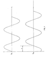
- Phase is the temporal relationship of two periodic phenomena, such as electrical signals in the present invention. Phase is measured in terms of a portion of a complete cycle of one of the signals. Thus, one cycle equals 360 0 or 2 ff radians.
- some standard point or landmark must be used. Since the signals may be square waves, as well as sine waves, the peaks are not generally used as the landmark.
- a conventional technique which has developed for measuring phase relationship is to utilize the positive-going zero crossing point, with zero defined as a level midway between the high and low extremes ( Figure 1). This is referred to as the "zero crossing technique” and is well known.
- Another known technique for generating a phase landmark is the "phase locked loop” technique.
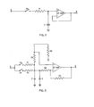
- phase demodulation system By way of background leading up to a discussion of the present invention a phase demodulation system will be outlined. Assume that A is a reference gating pulse, which synchronously gates or generates samples from another periodic signal S for some period, ⁇ T. The mean level then of the sampled signal is a function of the phase angle, e, between the two signals, although not unambiguously so. A simple single-sided sample and hold circuit for performing this task is shown in Figure 2.
- a second synchronous gating pulse B can be generated 180 0 delayed from the gate pulse A.
- a new "supra" time period is thus defined ( Figure 4), which is required for 6 (the phase relationship between GA and S) to cycle 2 ⁇ radians.
- a periodic signal, S A can be generated ( Figure 1).
- the position of the object can be determined from ⁇ .
- the situation with two signals with different phases can be expanded to include more than two phases.
- three drivers can be used unambiguously to determine the position of a rotatable hand. If three equal-amplitude wine wave signals were equally spaced over 2 ⁇ radians at 2 ⁇ /3 intervals, when summed, the vector sum is zero.
- the present invention uses a phase modulation/ demodulation technique to generate a resultant signal which is the superposition of a set of square waves.
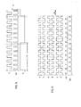
- the drive signals are not sine waves, but are phase modulated square waves with two levels, V DD and V SS . Only two phase conditions of the carrier signal of each of the drives are used.
- the drive signals have two possible phase transition points: 0 and ⁇ radians (0° and 180 0 ). Each drive has a 50% phase cycle (1/2T at O and 1/2T at ⁇ ).
- a single drive S synchronously demodulated by a single gate GA results in a simple square wave E ( Figure 5).
- the gate By driving square waves which have only two phases 180° apart, the gate can have a long sample period. The gate is not closed until all transients have died out or been suppressed. Thus the concept is well suited to digital implementation.
- drive pairs consisting of driver signals and their complements.
- Three such pairs of signals are used.
- One pair (A, A) phase transitions at O with respect to a reference signal.
- Drive signal A assumes what is arbitrarily termed the O-phase condition at O.
- a second phase pair (B, B) transitions at 2 ⁇ /3 (120°) with respect to the reference signal.
- a third phase pair (C, C ) transitions at 4 ⁇ /3 (240 0 ).
- the above are referred to as phase modulated drive signals.
- the driver array electrodes are physically arranged ( Figures 5a) at such angular positions which correspond or correlate with the phase of their phase shift with respect to the reference signal.
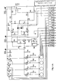
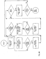
- the calculation of the phase angle of the signal directly from the six-step levels requires reading the step levels with an analog-to-digital converter and then performing an algorithm ( Figure 8). Contrary to the zero-crossing technique, this technique is not subject to component value changes. Additionally, the calculation method makes available a subsequent compensation based on the amplitude of the signal, which compensation will be related to the hand-to- transducer spacing.
- the calculation method is readily achieved with a microprocessor or microcomputer, although the method is compatible to a hardwired logic circuit.
- the microprocessor must have some sort of data base representing the levels of the six steps, if it is to generate a hand position. In the system of the present invention, no negative voltages are used, although this is not a requirement.
- the signals have a center voltage of some value V, with the steps being either greater or less than V.
- an 8-bit analog-to-digital converter to measure the levels and convert them into a digital representation in binary language. Due to the large variation in signal amplitude which results from the ordinary range of array-to-hand spacing, 10 bits of resolution is actually needed. To solve this problem there is utilized a variable gain prescaling amplifier in front of the step level acquisition circuit. (See Figure 8).
- This amplifier can have a gain of 1, 2, 3, or 4, all under the control of the microprocessor.
- the system is designed so that the voltage level V is in the center of the A/D converter range (the 8-bit range is 0-255, so the center point is at 127), thus the signal is at V + or - the step amplitude.
- the step levels are acquired in the following sequence:
- the levels are read into the microprocessor with an analog-to-digital converter.
- This device converts a voltage level into a binary code.
- An 8-bit A/D converter can resolve a voltage into one of 256 levels (2 8 ).
- the other 2 bits are generated with the variable gain preamplifier, which has an integer gain of from 1 to 4 (2 2 ) and is controlled by the microprocessor.
- the relationship of the signal acquisition elements is diagrammed in Figure 8.
- the digital logic circuit controls the timing of the gate closing so that the proper six-step level is sampled at the proper time.
- the six steps are acquired in the order described hereinabove to have the maximum time available between samples to allow the A/D converter to perform its function and because the steps will be analyzed in pairs in the order taken into the A/D converter.
- step 5 hereinabove the six-step levels have been acquired in a digital form (binary code), and the gain being utilized has been stored. The same gain is used for all six steps. This is because the actual calculation of the hand position to follow is a function primarily of the ratios of the levels.
- the absolute amplitude is only critical in applying the amplitude compensation value, and does not require great precision. As this system is ratio based in most of the algorithms involved, while it required 10-bit resolution, only 8- bit accuracy is required. Thus, larger tolerances can be tolerated in the amplifier gain.
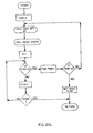
- the microprocessor or embodiment of the algorithms has several reliability checks built thereinto. For example the algorithm checks the time required for the A/D converter to respond with data. If more than a specified amount of time is required, the microprocessor or algorithm presumes a fault condition and.attemps to read the dial over. If there is a failure to respond the second time the system goes Into a fault mode and does not attempt to read the dial in question or any subsequent dial. The algorithm also checks certain characteristics of the six-step levels. If the signal is too large (i.e. six-step levels which deviate too much from -127.5), such signals will be too close to 0 or 255.
- the microprocessor presumes that the signal has either too high a voltage or too low a voltage, and it makes no difference which, as the result will be the same.
- the microprocessor steps through each of the stored six-step levels and checks to make sure that all are above some minimum value. If they are below that value, the entire set of values is rejected and the system attempts once again to read the six steps, going back through the gain setting part of the program. If the result is again faulty, the system presumes something is wrong and goes into the fault mode.
- Each pair of steps (1 and 2, 3 and 4, 5 and 6) should be symmetrical about the center line. If they are not, it is presumed that some sort of noise got into the system or that there is a problem someplace in the electronic circuit. In either case, the signal is not acceptable.
- the symmetry of the step pairs is tested by summing the pairs together, which sum should equal 255. If the sum deviates from 255 by more than some specified amount the data is presumed to be faulty and the system tries to reread the steps. Again, if the second rereading fails, the system goes into the fault mode. The test is quite powerful and useful.
- a test for too low a signal level is made later in the program during the amplitude compensation operation, as the signal level must be determined. If the signal is too low, the calculated hand position may be influenced by some residual or spurious signal and not due to the hand, so the system goes to the fault mode. These system checks do much to prevent a faulty reading from being transmitted.
- the six stepped signal at the central node is the superposition of three synchronously detected, square wave drive pair imbalances:
- step difference terms SDX
- A, B, and C have now been calculated and can be treated as vectors 120° apart. Since A, B, and C are all 9-bit values, they can no longer be kept in 8- bit registers, therefore, they are maintained in 16-bit registers (two 8-bit registers). This allows signed calculations to be accomplished using the 2's complement method, which is easier in a microprocessor. Since 16- bit registers are now being utilized, the valves can be normalized for preamplifier gain. This is done by multiplying each step difference (SD) by 4 and dividing the result by the gain G. To multiply by 4 in a microprocessor, the contents of the register are simply shifted to the left two places.
- SD step difference
- the three vectors define, and actually overdefine a resultant vector.
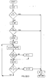
- the algorithm as implemented in the microprocessor reduces the A, B, and C vectors to a single vector at some angle with some magnitude. This is done through consolidation first into two vectors which are at right angles to each other.
- I and J are defined as unit vectors which are orthogonal (90° or ⁇ /2 radians apart). Such vectors are the x and y axes in Cartesian coordinates.
- I and J are calculated as follows: and
- I and J have now been calculated on a signed basis.
- the next step is to separate the signs from the values, converting the values into absolute values with the signs stored as separate sign flags (SI for the sign of I and SJ for the sign of J for later use).
- SI sign of the sign of I and SJ for the sign of J for later use.
- two new variables are created which are I and J with reduced resolution so that the resulting values will fit into 8-bit registers, keeping in mind that I and J are, at this instant, 11-bit values.
- This step is easily done by shifting the balues from I and J three bits to the right. All is now ready for calculation of the hand position.
- the microprocessor program determines if I is less than J, a swap flag (SF) is set and I and J are switched.
- the microprocessor finds an equivalent to the arctangent of J/I. Since the circle has been arbitrarily, but with ultimate purpose, divided into 640 parts, 45° is equal to 80 counts. Thus, the arctangent is in non-standard units.
- J is always less then or equal to I, hence a simple division would result in a value less than or equal to 1, a value not suited to integer arithmetic.
- the J value is multiplied by 256 by shifting it 8 bits to the left. This is done by concatenating an 8-bit word of zeros to the right.
- the resultant answer will be a value ranging from O to 255, a suitable range for binary logic.
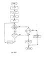
- the tangent equivalent K is converted into angular equivalent units (WC's) through the use of a successive approximation algorithm which utilizes an 80 point sequential table.
- the table is generated by the following simple BASIC program:
- Successive approximation is a process of converging on a value or solution by making a series of guesses within a set of rules.
- Two limits are defined, an upper and lower limit; the designated value is then compared to the value stored in the register midway between the upper and lower limits. If K is greater, then the midpoint becomes the new lower limit. Conversely, if K is less than the midpoint, then the midpoint pointer becomes the new upper limit. The process is repeated until a single value is converged upon.
- the following variables are defined:
- SAS successive approximation subroutine
- Offset compensation is a baseline correction for the gross rotation of the array pattern.
- the offset compensation value is generated when the amplitude compensation table is generated, as OS defines a starting point to be used on the amplitude compensation curve.
- RA offset and the amplitude
- a, b, and c are constants which are generated from experimental data. This experimental data involves generating amplitudes (RA) and uncompensated W's at a number of known hand positions at a number of known spacings (z's). From these values the constants a, b, and c are generated by multiple regression techniques.
- the total offset could be calculated directly; however, it would require a considerable amount of memory space and time in the microprocessor based system, so a lookup table is used.
- the amplitude is calculated from vectors I and J as follows:
- the program uses the lookup table as follows:
- Dial D 2 is very close to the transition from "3" to "4". Thus, it can be seen that it should be read as a "3", for dial D 1 is close to, but has not yet passed the transition from 9 to 0, which would cause the next dial to logically transition to the higher digit.
- an adjustment factor derived from the reading of the previous dial is added to remove this potential ambiguity. It is important to note that the adjusted reading of the previous dial is used in determining this adjustment factor: thus an adjustment factor determined in reading a previous (less significant) adjacent dial is applied to the reading of a subsequent (more significant) dial. More formally the generation of an interdial correction factor for the more significant adjacent dial is always performed after the generation of the correction factor from the previous dial. The determination of all such correction factors proceeds as follows. The transition of the more significant digit of a digit pair should occur upon the transition of the less significant dial from 9 to 0. The value of the less significant digit contains the correct information to resolve possible ambiguities of the more significant digit. In the following discussion these terms will be used:
- each digit dial can be resolved into d, digitized levels, and that for initial considerations, d is a large number approaching, for practical purposes, infinity; note that resolution is merely the number of digitized levels, and is not the accuracy of the determination of hand position, although it represents the upper limit of accuracy for a single reading.
- Digit value, D' is related to the digit levels, d', by the ratio:
- Equation (3) thus becomes (using equation (1)): the quantity comprising the correction factor to be added from the previous less significant dial and to be independently determined for the next more significant dial. [Note ( 1 ) that( ) 1/ 2 is used rather than( ) 1/2 because d is not a continuous variable; (2) that strictly speaking E q. 4 is equivalent to( -1) which approaches 2 in the limit as n ⁇ ].
- R The desired digit reading of the n th dial, D , shall be called R , such that:
- the value of Y 1 is initialized to 128. Note that in calculating the 2560 count value of dial 1 (the least significant dial) there is first added 128 to the reading, and then subtract the initialized value of Y 1 (128) from it. In other words, it is unaffected.
- the process is as follows:
Landscapes
- Physics & Mathematics (AREA)
- General Physics & Mathematics (AREA)
- Engineering & Computer Science (AREA)
- Signal Processing (AREA)
- Transmission And Conversion Of Sensor Element Output (AREA)
- Measurement Of Length, Angles, Or The Like Using Electric Or Magnetic Means (AREA)
Applications Claiming Priority (2)
| Application Number | Priority Date | Filing Date | Title |
|---|---|---|---|
| US06/516,714 US4606008A (en) | 1983-07-25 | 1983-07-25 | Angular position detector |
| US516714 | 1983-07-25 |
Related Parent Applications (2)
| Application Number | Title | Priority Date | Filing Date |
|---|---|---|---|
| EP84304955A Division-Into EP0138306B1 (de) | 1983-07-25 | 1984-07-20 | Winkellagendetektor |
| EP84304955A Division EP0138306B1 (de) | 1983-07-25 | 1984-07-20 | Winkellagendetektor |
Publications (1)
| Publication Number | Publication Date |
|---|---|
| EP0247643A1 true EP0247643A1 (de) | 1987-12-02 |
Family
ID=24056798
Family Applications (4)
| Application Number | Title | Priority Date | Filing Date |
|---|---|---|---|
| EP84304955A Expired EP0138306B1 (de) | 1983-07-25 | 1984-07-20 | Winkellagendetektor |
| EP87200411A Withdrawn EP0247643A1 (de) | 1983-07-25 | 1984-07-20 | Winkelstellungsdetektor |
| EP87200409A Withdrawn EP0247642A1 (de) | 1983-07-25 | 1984-07-20 | Winkelstellungsdetektor |
| EP87200410A Withdrawn EP0241062A1 (de) | 1983-07-25 | 1984-07-20 | Winkellagendetektor |
Family Applications Before (1)
| Application Number | Title | Priority Date | Filing Date |
|---|---|---|---|
| EP84304955A Expired EP0138306B1 (de) | 1983-07-25 | 1984-07-20 | Winkellagendetektor |
Family Applications After (2)
| Application Number | Title | Priority Date | Filing Date |
|---|---|---|---|
| EP87200409A Withdrawn EP0247642A1 (de) | 1983-07-25 | 1984-07-20 | Winkelstellungsdetektor |
| EP87200410A Withdrawn EP0241062A1 (de) | 1983-07-25 | 1984-07-20 | Winkellagendetektor |
Country Status (4)
| Country | Link |
|---|---|
| US (1) | US4606008A (de) |
| EP (4) | EP0138306B1 (de) |
| CA (1) | CA1238388A (de) |
| MX (1) | MX157984A (de) |
Families Citing this family (23)
| Publication number | Priority date | Publication date | Assignee | Title |
|---|---|---|---|---|
| US4606008A (en) | 1983-07-25 | 1986-08-12 | Cain Encoder Company | Angular position detector |
| GB8423086D0 (en) * | 1984-09-12 | 1984-10-17 | March A A C | Position sensor |
| US4858142A (en) * | 1987-08-05 | 1989-08-15 | Tektronix, Inc. | Digitizer effective resolution measurement system using sinewave parameter estimation |
| US4901072A (en) * | 1988-02-17 | 1990-02-13 | Westinghouse Electric Corp. | Position detector utilizing gray code format |
| US4924407A (en) * | 1988-08-15 | 1990-05-08 | Siecor Corporation | Humidity resistant meter reading device |
| CA2003095A1 (en) * | 1989-10-20 | 1991-04-20 | Siecor Corporation | An improved meter reading device |
| US5030950A (en) * | 1989-10-23 | 1991-07-09 | Siecor Corporation | Switched capacitance meter reading device |
| US5136286A (en) * | 1990-01-29 | 1992-08-04 | Siecor Corporation | Switched capacitance meter reading device using variable width electrodes |
| DE4232864A1 (de) * | 1992-09-30 | 1994-03-31 | Thomson Brandt Gmbh | Drehwinkel-, Drehzahl- und Drehrichtungsmessung |
| GB9320346D0 (en) * | 1993-10-02 | 1993-12-22 | Lucas Ind Publci Limited Compa | Apparatus for compensating for phase shift |
| US5590059A (en) * | 1995-03-14 | 1996-12-31 | Schier; J. Alan | Position encoder system which utilites the fundamental frequency of a ruled scale on an object |
| US6211641B1 (en) * | 1999-05-12 | 2001-04-03 | Trw Inc. | Capacitive resolver |
| US6660996B1 (en) | 2001-07-03 | 2003-12-09 | Lexmark International, Inc. | System and method for examining relationship between intersecting encoder output signals |
| US20080052033A1 (en) * | 2004-08-12 | 2008-02-28 | University Of Virginia Patent Foundation | Method, Apparatus and Computer Program Product of Aliasing Discriminator for Encoder Interfaces |
| US8035074B2 (en) * | 2009-02-09 | 2011-10-11 | Avago Technologies Ecbu Ip (Singapore) Pte. Ltd. | Automatic gain control for motion encoder signals |
| JP5479236B2 (ja) * | 2010-06-15 | 2014-04-23 | キヤノン株式会社 | ロータリーエンコーダ |
| JP5574899B2 (ja) * | 2010-09-24 | 2014-08-20 | キヤノン株式会社 | ロータリーエンコーダ及びこれを備えた光学機器 |
| DE102012203225A1 (de) * | 2012-03-01 | 2013-09-05 | Tyco Electronics Amp Gmbh | Verfahren zum berührungslosen messen einer relativen position mittels eines 3d-hallsensors mit messsignalspeicher |
| CN109099938B (zh) * | 2018-07-04 | 2020-11-24 | 哈尔滨理工大学 | 基于极数查表的角度区间扫描角度值跳点抑制方法及装置 |
| US11181397B2 (en) * | 2019-11-01 | 2021-11-23 | Sensus Spectrum, Llc | High-resolution index (HRI) detector modules including capacitive sensors and related systems |
| CN111693073B (zh) * | 2020-06-28 | 2022-01-25 | 哈尔滨理工大学 | 一种双向冗余磁电编码器及其冗余检测方法 |
| DE102021005044B4 (de) * | 2021-10-08 | 2024-07-11 | Baumer Germany Gmbh & Co. Kg | Messdatenprozessor, Positionsmessgerät und computerimplementiertes Verfahren |
| CN115930763B (zh) * | 2022-12-08 | 2023-12-05 | 楚瑞智能科技(苏州)有限公司 | 一种基于磁栅尺的位移测量方法及装置 |
Citations (10)
| Publication number | Priority date | Publication date | Assignee | Title |
|---|---|---|---|---|
| US3500365A (en) | 1968-11-12 | 1970-03-10 | Charles J Cain | Apparatus for remotely determining the angular orientation,speed,and/or direction of rotation of objects |
| DE2523163A1 (de) * | 1974-06-17 | 1976-01-02 | Ibm | Kapazitiver differentialmesswandler |
| US4007454A (en) | 1975-09-12 | 1977-02-08 | Charles J. Cain | Apparatus for remotely determining the angular orientation, speed, and/or direction of rotation of objects |
| DE2853142A1 (de) * | 1977-12-09 | 1979-06-21 | Stiftelsen Inst Mikrovags | Messvorrichtung zur kapazitiven bestimmung der relativen lagen zweier zueinander beweglicher teile |
| US4214152A (en) | 1978-05-12 | 1980-07-22 | Cain Encoder Company | Error correction in a remote meter reading device |
| DE3020411A1 (de) * | 1980-05-27 | 1981-12-24 | Hans Ulrich St.Sulpice Waadt Meyer | Kapazitive vorrichtung zur messung von verschiebungen |
| DE3144506A1 (de) * | 1980-11-10 | 1982-08-26 | Nippon Soken, Inc., Nishio, Aichi | "kapazitive wegstrecken-messeinrichtung" |
| US4429308A (en) | 1976-09-30 | 1984-01-31 | Charles J. Cain | Electrode or pole piece array for creating prescribed electric or magnetic fields |
| US4433332A (en) | 1980-11-24 | 1984-02-21 | Cain Encoder Co. | Apparatus for remotely determining the position of rotating objects |
| EP0138306A1 (de) | 1983-07-25 | 1985-04-24 | Cain Encoder Company | Winkellagendetektor |
Family Cites Families (16)
| Publication number | Priority date | Publication date | Assignee | Title |
|---|---|---|---|---|
| US3219995A (en) * | 1961-04-03 | 1965-11-23 | Bendix Corp | Analog-to-digital converter |
| US3284795A (en) * | 1964-03-31 | 1966-11-08 | Fertig Kenneth | Angular resolver |
| GB1105810A (en) * | 1966-04-28 | 1968-03-13 | Aga Ab | Generating an angle-representative voltage |
| DE1919079C3 (de) * | 1968-05-08 | 1975-04-24 | Fujitsu Ltd., Kawasaki, Kanagawa (Japan) | Numerische Steuervorrichtung |
| JPS517059B1 (de) * | 1969-12-31 | 1976-03-04 | ||
| US3683368A (en) * | 1970-10-22 | 1972-08-08 | Houston Natural Gas Corp | Digital encoding transducer |
| US3935568A (en) * | 1971-11-24 | 1976-01-27 | Lem Instrument Corporation | Universal analog-to-digital converter using the same information disc for different output codes |
| US3868680A (en) * | 1974-02-04 | 1975-02-25 | Rockwell International Corp | Analog-to-digital converter apparatus |
| US3961318A (en) * | 1975-01-17 | 1976-06-01 | Inductosyn Corporation | Electrostatic position-measuring transducer |
| SE406642B (sv) * | 1977-02-16 | 1979-02-19 | Aga Ab | Elektromekanisk legesgivare |
| JPS5756318Y2 (de) * | 1978-05-15 | 1982-12-03 | ||
| GB2034991B (en) * | 1978-11-16 | 1983-03-02 | Vickers Ltd | Encoding switches |
| US4315198A (en) * | 1979-11-07 | 1982-02-09 | Qume Corporation | Digital servo system |
| US4346447A (en) * | 1979-12-28 | 1982-08-24 | Nippon Kogaku K.K. | Divisional reading device for sine signals |
| GB2100941B (en) * | 1981-06-08 | 1984-08-15 | Philips Electronic Associated | Waveform crossing detector |
| US4429307A (en) * | 1982-01-29 | 1984-01-31 | Dataproducts Corporation | Capacitive transducer with continuous sinusoidal output |
-
1983
- 1983-07-25 US US06/516,714 patent/US4606008A/en not_active Expired - Lifetime
-
1984
- 1984-07-20 EP EP84304955A patent/EP0138306B1/de not_active Expired
- 1984-07-20 EP EP87200411A patent/EP0247643A1/de not_active Withdrawn
- 1984-07-20 EP EP87200409A patent/EP0247642A1/de not_active Withdrawn
- 1984-07-20 EP EP87200410A patent/EP0241062A1/de not_active Withdrawn
- 1984-07-24 CA CA000459531A patent/CA1238388A/en not_active Expired
- 1984-07-25 MX MX202193A patent/MX157984A/es unknown
Patent Citations (10)
| Publication number | Priority date | Publication date | Assignee | Title |
|---|---|---|---|---|
| US3500365A (en) | 1968-11-12 | 1970-03-10 | Charles J Cain | Apparatus for remotely determining the angular orientation,speed,and/or direction of rotation of objects |
| DE2523163A1 (de) * | 1974-06-17 | 1976-01-02 | Ibm | Kapazitiver differentialmesswandler |
| US4007454A (en) | 1975-09-12 | 1977-02-08 | Charles J. Cain | Apparatus for remotely determining the angular orientation, speed, and/or direction of rotation of objects |
| US4429308A (en) | 1976-09-30 | 1984-01-31 | Charles J. Cain | Electrode or pole piece array for creating prescribed electric or magnetic fields |
| DE2853142A1 (de) * | 1977-12-09 | 1979-06-21 | Stiftelsen Inst Mikrovags | Messvorrichtung zur kapazitiven bestimmung der relativen lagen zweier zueinander beweglicher teile |
| US4214152A (en) | 1978-05-12 | 1980-07-22 | Cain Encoder Company | Error correction in a remote meter reading device |
| DE3020411A1 (de) * | 1980-05-27 | 1981-12-24 | Hans Ulrich St.Sulpice Waadt Meyer | Kapazitive vorrichtung zur messung von verschiebungen |
| DE3144506A1 (de) * | 1980-11-10 | 1982-08-26 | Nippon Soken, Inc., Nishio, Aichi | "kapazitive wegstrecken-messeinrichtung" |
| US4433332A (en) | 1980-11-24 | 1984-02-21 | Cain Encoder Co. | Apparatus for remotely determining the position of rotating objects |
| EP0138306A1 (de) | 1983-07-25 | 1985-04-24 | Cain Encoder Company | Winkellagendetektor |
Also Published As
| Publication number | Publication date |
|---|---|
| MX157984A (es) | 1988-12-28 |
| EP0138306B1 (de) | 1989-04-05 |
| EP0241062A1 (de) | 1987-10-14 |
| CA1238388A (en) | 1988-06-21 |
| EP0247642A1 (de) | 1987-12-02 |
| US4606008A (en) | 1986-08-12 |
| EP0138306A1 (de) | 1985-04-24 |
Similar Documents
| Publication | Publication Date | Title |
|---|---|---|
| EP0247643A1 (de) | Winkelstellungsdetektor | |
| US4318617A (en) | DC Shift error correction for electro-optical measuring system | |
| US4580046A (en) | Displacement measuring device utilizing an incremental code | |
| US4238781A (en) | Capacitive angular displacement transducer for remote meter reading | |
| US4346447A (en) | Divisional reading device for sine signals | |
| JPH0368812A (ja) | 位置測定信号の内挿方法 | |
| EP0244385B1 (de) | Verlagerungsdetektor für einen Codierer | |
| RU2020752C1 (ru) | Преобразователь угла поворота вала в код | |
| US4710889A (en) | Angular position detector | |
| US5098187A (en) | Apparatus and method for signal generation and for processing | |
| US4787054A (en) | Interdial compensation technique for angular position detectors | |
| US4754411A (en) | Angular position detector | |
| US4506333A (en) | Device for measuring the phase angle between a sine wave signal and a cyclic logic signal of the same frequency | |
| US4704690A (en) | Angular position detector | |
| JPS61137011A (ja) | エンコ−ダ出力の精度向上方法 | |
| CA1269146A (en) | Angular position detector | |
| US3573801A (en) | Synchro to digital converter | |
| US3440644A (en) | Synchro-to-digital converter | |
| JPS62235503A (ja) | 容量型位置測定トランスデユ−サ | |
| EP0015788B1 (de) | Gerät und Verfahren zur periodischen Erzeugung einer Messanzeige mit verbesserter Stabilität | |
| USH104H (en) | Digital resolver compensation technique | |
| CA1119270A (en) | Error correction in a remote meter reading device | |
| US4703309A (en) | Precision optoelectronic rotational position sensor | |
| RU2071174C1 (ru) | Преобразователь угла поворота вала в код | |
| US3898649A (en) | Encoder device for use with polydecade consumption or usage meters |
Legal Events
| Date | Code | Title | Description |
|---|---|---|---|
| PUAI | Public reference made under article 153(3) epc to a published international application that has entered the european phase |
Free format text: ORIGINAL CODE: 0009012 |
|
| 17P | Request for examination filed |
Effective date: 19870425 |
|
| AC | Divisional application: reference to earlier application |
Ref document number: 138306 Country of ref document: EP |
|
| AK | Designated contracting states |
Kind code of ref document: A1 Designated state(s): AT BE CH DE FR GB IT LI LU NL SE |
|
| 17Q | First examination report despatched |
Effective date: 19890502 |
|
| STAA | Information on the status of an ep patent application or granted ep patent |
Free format text: STATUS: THE APPLICATION IS DEEMED TO BE WITHDRAWN |
|
| 18D | Application deemed to be withdrawn |
Effective date: 19900619 |
|
| RIN1 | Information on inventor provided before grant (corrected) |
Inventor name: WASON, THOMAS D. |