EP0247976B1 - Kraftfahrzeuggetriebe - Google Patents
Kraftfahrzeuggetriebe Download PDFInfo
- Publication number
- EP0247976B1 EP0247976B1 EP87830173A EP87830173A EP0247976B1 EP 0247976 B1 EP0247976 B1 EP 0247976B1 EP 87830173 A EP87830173 A EP 87830173A EP 87830173 A EP87830173 A EP 87830173A EP 0247976 B1 EP0247976 B1 EP 0247976B1
- Authority
- EP
- European Patent Office
- Prior art keywords
- axial
- control rod
- engagement
- reverse
- selection
- Prior art date
- Legal status (The legal status is an assumption and is not a legal conclusion. Google has not performed a legal analysis and makes no representation as to the accuracy of the status listed.)
- Expired
Links
- 238000006073 displacement reaction Methods 0.000 claims description 9
- 230000007935 neutral effect Effects 0.000 description 2
- 230000000694 effects Effects 0.000 description 1
Images

Classifications
-
- F—MECHANICAL ENGINEERING; LIGHTING; HEATING; WEAPONS; BLASTING
- F16—ENGINEERING ELEMENTS AND UNITS; GENERAL MEASURES FOR PRODUCING AND MAINTAINING EFFECTIVE FUNCTIONING OF MACHINES OR INSTALLATIONS; THERMAL INSULATION IN GENERAL
- F16H—GEARING
- F16H61/00—Control functions within control units of change-speed- or reversing-gearings for conveying rotary motion ; Control of exclusively fluid gearing, friction gearing, gearings with endless flexible members or other particular types of gearing
- F16H61/18—Preventing unintentional or unsafe shift, e.g. preventing manual shift from highest gear to reverse gear
-
- F—MECHANICAL ENGINEERING; LIGHTING; HEATING; WEAPONS; BLASTING
- F16—ENGINEERING ELEMENTS AND UNITS; GENERAL MEASURES FOR PRODUCING AND MAINTAINING EFFECTIVE FUNCTIONING OF MACHINES OR INSTALLATIONS; THERMAL INSULATION IN GENERAL
- F16H—GEARING
- F16H61/00—Control functions within control units of change-speed- or reversing-gearings for conveying rotary motion ; Control of exclusively fluid gearing, friction gearing, gearings with endless flexible members or other particular types of gearing
- F16H61/18—Preventing unintentional or unsafe shift, e.g. preventing manual shift from highest gear to reverse gear
- F16H2061/185—Means, e.g. catches or interlocks, for preventing unintended shift into reverse gear
Definitions
- the present invention refers in general to gearboxes having five forward ratios and one reverse ratio.
- the invention relates to a gearbox having five ratios and reverse, in which an extra movement of the gear lever is provided for the engagement of reverse.
- a gearbox of this type includes a control rod supported by a support structure in a slidable and rotatable manner and having an outer end and an inner end carrying a selection and engagement member, the control rod being axially displaceable between four successive axial selection positions in the first of which it allows the selection of the first or second speed ratio, in the second the selection of the third or fourth speed ratio, in the third the selection of the fifth speed ratio, and in the fourth the selection of reverse, resilient means tending to maintain the control rod in the second axial position and the control rod being rotatable, in correspondence with the axial selection positions, into first or second opposite angular positions to obtain, respectively, the engagement of the first or second speed ratio, the third or fourth speed ratio, the fifth speed ratio and reverse.
- the object of the present invention is that of realising a gearbox of the type defined above equipped with a safety device of simple and economic realisation and safe and reliable operation.
- the invention has for its subject a gearbox of the type initially specified, characterized in that it is provided with a safety device for avoiding accidental engagement of reverse with the control rod inthe axial position of engagement of the fifth speed ratio, comprising a catch appendage projecting radially from the control rod in the region of its outer end, and a locking member in the form of a bush traversed in a slidable and rotatable manner by the control rod and having an axial notch along which the catch appendage moves freely in an axial direction between the four axial selection positions of the control rod, the notch being shaped in such a manner to prevent angular displacement of the control rod from the angular position of engagement of the fifth speed ratio towards the angular position of engagement of reverse when the control rod is in the third axial selection position, and to allow this angular displacement for engagement of reverse only when the control rod is disposed in the fourth axial selection position.
- a safety device for avoiding accidental engagement of reverse with the control rod inthe axial position of engagement of the fifth
- the notch in the bush conveniently has a restriction in axial correspondence with the position assumed by the catch appendage in the third axial engagement position and in angular correspondence with the position assumed by the catch appendage in the angular position of engagement of reverse, and a widening in axial correspondence with the position assumed by the catch appendage in the fourth axial engagement position and in angular correspondence with the position assumed by the catch appendage in the angular position of engagement of reverse.
- the catch appendage conveniently has a cylindrical form flattened on one side, and the widening of the notch is defined by a flat end surface of the bush above which the flattened side of the catch appendage is disposed in the reverse engagement position.
- Figure 1 illustrates schematically a part of a motor vehicle gearbox having five forward speed ratios and one reverse speed ratio, the general configuration of which is conventional and, for brevity, will therefore not be described in detail.
- the gearbox comprises a series of pairs of gears always in mesh with one another and synchronizing devices for controlling the engagement of the various speed ratios operated by means of forks carried by three slidable engagement rods respectively for the engagement of the first or second ratio, the third or fourth ratio, the fifth ratio or reverse.
- the displacement of the engagement rods is effected by means of a rod or control shaft 1 supported by the support structure (box 2) of the gearbox.
- the control rod 1 is translatable along its axis, indicated A, and rotatable about this axis by means of a manually-operated gear lever (not illustrated), in a manner known to an expert in the field.
- the control rod 1 has an outer end 1a projecting outwardly of the structure 2 and rotatably mounted in and slidable through a bush 3 fixed to this structure 2 and forming part of a safety device 4 which will be described below, and an inner end 1b.
- This inner end 1 b carries a radial finger 5 for operating, in a manner known in itself, the three engagement rods with their forks.
- the control rod 1 is axially displaceable between four axial selection positions, the second of which is illustrated in Figure 1 and constitutes a stable position in that the control rod 1 is normally urged axially into this position by a pair of opposing helical return springs 6, 7.
- this second axial position which corresponds to selection of the third and fourth speed ratios, the radial finger 5 is disposed in the condition shown in continuous outline in Figure 1.
- the radial finger -5 is disposed in the respective positions indicated 5', 5" and 5"' in broken outline in Figure 1 and corresponding respectively to the selection of the first and second speed ratios, the fifth speed ratio, and reverse.
- the control rod 1 performs a supplementary axial movement with respect to the position for selection of the fifth speed ratio.
- first and second axial selection positions the rotation of the control rod 1 in one sense or in the opposite sense allows one ratio or the other of the selected pair to be engaged.
- first selection position position 5' of the radial finger 5
- second selection position position 5 of the radial finger 5
- the safety device 4 associated with the outer end region of the control rod 1 has the function of preventing the angular displacement of the fifth speed ratio towards the angular position of engagement of reverse when the control rod is in the third axial selection position (position 5" of the radial finger 5), and to allow such angular displacement for engagement of reverse solely when the control rod 1 is disposed in the fourth axial selection position (position 5'" of the radial finger 5).
- the function of the safety device 4 is that of avoiding accidental or unwanted engagement of reverse during forward motion of the vehicle in which the gearbox is mounted because of an incorrect movement of the gear lever by the driver, when the control rod is in the axial position of engagement of the fifth speed ratio.
- This safety device 4 includes, as well as the bush 3 which will be described in detail further on, a radial catch appendage 8 carried by the control rod 1 in the region of its outer end la, and more particularly, in the region corresponding to the bush 3.
- the catch appendage 8 is constituted by a pin force-fitted into a hole 9 of the rod 1 and having a generally cylindrical form with a flattened lower side 8a.
- the bush 3 has a generally cylindrical form with a lower portion 10 functioning as a rest for the spring 6, an intermediate portion 11, and an upper widened portion 12 forming a flange for the fixing of the bush 3 to the structure 2 of the gearbox.
- Opening into the cavity of the bush 3 is an inner axial notch 13 which extends along the intermediate portion 11 and upper portion 12 and along which the catch appendage 8 of.the control rod 1 is free to move axially between the four axial selection positions of this rod 1.
- the axial portion of the notch 13 corresponding to the axial position assumed by the catch appendage 8 in the first and second axial selection positions of the control rod 1 has a width such as to allow, in these axial positions, the free rotation of the catch appendage 8 in one sense or in the opposite sense corresponding respectively to the angular positions of the control rod 1 for engagement of the first or third and the second or fourth speed ratios.
- the axial notch 13 opens axially onto the upper flange portion 12 of the bush 3 in correspondence with the axial position assumed by the catch appendage 8 in the fourth axial selection position of the control rod 1. Therefore, when the control rod 1 is disposed in the fourth axial selection position, angular displacement for engagement of reverse is allowed because of which the flat surface 8a of the catch appendage 8 is disposed above the upper face of the flange portion 12 of the bush 3.
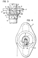
- Figure 3 illustrates schematically the different relative positions of the catch bush 8 and the axial notch 13 of the bush 3 in correspondence with the different axial selection positions and angular engagement positions of the control rod 1. These positions, indicated I, II, III, F, IV, V, RM, correspond exactly to the conditions of engagement of the first, second and third speed ratios, to the neutral condition, and to the conditions of engagement of the fourth and fifth speed ratios and reverse, respectively.
- the catch appendage 8 is illustrated in continuous outline in the neutral position F and in broken outline in the reverse engagement position RM.
Landscapes
- Engineering & Computer Science (AREA)
- General Engineering & Computer Science (AREA)
- Mechanical Engineering (AREA)
- Gear-Shifting Mechanisms (AREA)
- Motor Power Transmission Devices (AREA)
Claims (3)
Applications Claiming Priority (2)
| Application Number | Priority Date | Filing Date | Title |
|---|---|---|---|
| IT6743586 | 1986-05-27 | ||
| IT67435/86A IT1190573B (it) | 1986-05-27 | 1986-05-27 | Cambio di velocita a cinque rapporti e retromarcia pe autoveicoli |
Publications (2)
| Publication Number | Publication Date |
|---|---|
| EP0247976A1 EP0247976A1 (de) | 1987-12-02 |
| EP0247976B1 true EP0247976B1 (de) | 1990-02-07 |
Family
ID=11302366
Family Applications (1)
| Application Number | Title | Priority Date | Filing Date |
|---|---|---|---|
| EP87830173A Expired EP0247976B1 (de) | 1986-05-27 | 1987-05-11 | Kraftfahrzeuggetriebe |
Country Status (4)
| Country | Link |
|---|---|
| EP (1) | EP0247976B1 (de) |
| DE (1) | DE3761695D1 (de) |
| ES (1) | ES2013306B3 (de) |
| IT (1) | IT1190573B (de) |
Families Citing this family (3)
| Publication number | Priority date | Publication date | Assignee | Title |
|---|---|---|---|---|
| DE19619182C2 (de) * | 1996-05-11 | 1998-07-02 | Ford Werke Ag | Schaltvorrichtung für Wechselgetriebe mit einer Rückwärtsgang-Schaltsperre |
| DE102009027533A1 (de) * | 2009-07-08 | 2011-01-20 | Zf Friedrichshafen Ag | Schaltvorrichtung eines Kraftfahrzeug-Schaltgetriebes |
| DE102013215768B4 (de) * | 2013-04-25 | 2021-05-20 | GM Global Technology Operations, LLC (n.d. Ges. d. Staates Delaware) | Schaltmechanismus für ein Kraftfahrzeuggetriebe |
Family Cites Families (7)
| Publication number | Priority date | Publication date | Assignee | Title |
|---|---|---|---|---|
| NL239031A (de) * | 1958-05-10 | |||
| JPS521458B2 (de) * | 1972-01-24 | 1977-01-14 | ||
| JPS522063B2 (de) * | 1973-11-19 | 1977-01-19 | ||
| JPS54105681A (en) * | 1978-02-06 | 1979-08-18 | Nissan Motor Co Ltd | Speed change operation structure for speed change gear |
| DE3016909C2 (de) * | 1980-05-02 | 1982-11-04 | Audi Nsu Auto Union Ag, 7107 Neckarsulm | Schaltvorrichtung für ein mehrgängiges Zahnräder-Wechselgetriebe |
| JPS6215556Y2 (de) * | 1981-03-30 | 1987-04-20 | ||
| JPH0665909B2 (ja) * | 1984-07-09 | 1994-08-24 | 富士重工業株式会社 | 車両用変速歯車装置の変速操作機構 |
-
1986
- 1986-05-27 IT IT67435/86A patent/IT1190573B/it active
-
1987
- 1987-05-11 ES ES87830173T patent/ES2013306B3/es not_active Expired - Lifetime
- 1987-05-11 EP EP87830173A patent/EP0247976B1/de not_active Expired
- 1987-05-11 DE DE8787830173T patent/DE3761695D1/de not_active Expired - Fee Related
Also Published As
| Publication number | Publication date |
|---|---|
| IT1190573B (it) | 1988-02-16 |
| EP0247976A1 (de) | 1987-12-02 |
| IT8667435A0 (it) | 1986-05-27 |
| ES2013306B3 (es) | 1990-05-01 |
| DE3761695D1 (de) | 1990-03-15 |
Similar Documents
| Publication | Publication Date | Title |
|---|---|---|
| EP0383493B1 (de) | Verbundgetriebe und zugehörige Schaltsteuerung | |
| EP0395241B1 (de) | Schaltmechanismus mit einer einzigen Schaltstange | |
| US5000060A (en) | Compound transmission and shift control therefor | |
| US5285694A (en) | Shift plate actuated single shaft shifting mechanism | |
| US4320670A (en) | Shift interlock mechanism of a vehicle power transmission | |
| US4307624A (en) | Transmission gear selector arm and sleeves for shifting forks | |
| EP0460181B1 (de) | Gangschalthebel für ein fahrzeuggetriebe | |
| US4132125A (en) | Shift mechanism in a motor vehicle gear box | |
| US4337673A (en) | Control apparatus for a vehicle power transmission | |
| EP0247976B1 (de) | Kraftfahrzeuggetriebe | |
| EP0149020B1 (de) | Getriebeschalt- und Steuervorrichtung, insbesondere für Nutzfahrzeuge | |
| US5186070A (en) | Gear-change device for the transmission of a motor vehicle | |
| US6122983A (en) | Shift device for a manual transmission | |
| US4485689A (en) | Shift control assembly | |
| US6487927B1 (en) | Automatic neutral finder for a motorcycle transmission | |
| EP0170630B1 (de) | Steuervorrichtung eines Wechselgetriebes für Kraftwagen | |
| CA1122809A (en) | Control mechanism for a vehicle ignition lock | |
| US5778728A (en) | Gear shifting device for a change-speed gearbox, particularly for motor vehicles | |
| EP0204664B1 (de) | Getriebe für Motorfahrzeug mit dauernd in Eingriff stehenden Zahnrädern | |
| CA1093429A (en) | Escapement assembly for shift control mechanism | |
| US4096717A (en) | Transmission shift control | |
| GB2127503A (en) | Selector mechanism having a manual gearshift lever for main and auxiliary gearboxes in series | |
| JPS58106257A (ja) | 歯車変速機の変速操作機構 | |
| EP0249582B1 (de) | Sicherheitseinrichtung für die Steuerstange eines Fahrzeuggetriebes mit fünf Gängen und Rückwärtsgang | |
| EP0685667B1 (de) | Gangwähleinrichtung für ein Getriebe |
Legal Events
| Date | Code | Title | Description |
|---|---|---|---|
| PUAI | Public reference made under article 153(3) epc to a published international application that has entered the european phase |
Free format text: ORIGINAL CODE: 0009012 |
|
| AK | Designated contracting states |
Kind code of ref document: A1 Designated state(s): DE ES FR GB SE |
|
| 17P | Request for examination filed |
Effective date: 19871127 |
|
| 17Q | First examination report despatched |
Effective date: 19880922 |
|
| GRAA | (expected) grant |
Free format text: ORIGINAL CODE: 0009210 |
|
| AK | Designated contracting states |
Kind code of ref document: B1 Designated state(s): DE ES FR GB SE |
|
| REF | Corresponds to: |
Ref document number: 3761695 Country of ref document: DE Date of ref document: 19900315 |
|
| ET | Fr: translation filed | ||
| PLBE | No opposition filed within time limit |
Free format text: ORIGINAL CODE: 0009261 |
|
| STAA | Information on the status of an ep patent application or granted ep patent |
Free format text: STATUS: NO OPPOSITION FILED WITHIN TIME LIMIT |
|
| 26N | No opposition filed | ||
| PGFP | Annual fee paid to national office [announced via postgrant information from national office to epo] |
Ref country code: GB Payment date: 19930415 Year of fee payment: 7 |
|
| PGFP | Annual fee paid to national office [announced via postgrant information from national office to epo] |
Ref country code: SE Payment date: 19930430 Year of fee payment: 7 |
|
| PGFP | Annual fee paid to national office [announced via postgrant information from national office to epo] |
Ref country code: ES Payment date: 19930517 Year of fee payment: 7 |
|
| PG25 | Lapsed in a contracting state [announced via postgrant information from national office to epo] |
Ref country code: GB Effective date: 19940511 |
|
| PG25 | Lapsed in a contracting state [announced via postgrant information from national office to epo] |
Ref country code: SE Effective date: 19940512 Ref country code: ES Free format text: LAPSE BECAUSE OF NON-PAYMENT OF DUE FEES Effective date: 19940512 |
|
| GBPC | Gb: european patent ceased through non-payment of renewal fee |
Effective date: 19940511 |
|
| EUG | Se: european patent has lapsed |
Ref document number: 87830173.8 Effective date: 19941210 |
|
| EUG | Se: european patent has lapsed |
Ref document number: 87830173.8 |
|
| PGFP | Annual fee paid to national office [announced via postgrant information from national office to epo] |
Ref country code: DE Payment date: 19960424 Year of fee payment: 10 |
|
| PGFP | Annual fee paid to national office [announced via postgrant information from national office to epo] |
Ref country code: FR Payment date: 19960530 Year of fee payment: 10 |
|
| PG25 | Lapsed in a contracting state [announced via postgrant information from national office to epo] |
Ref country code: FR Free format text: LAPSE BECAUSE OF NON-PAYMENT OF DUE FEES Effective date: 19980130 |
|
| PG25 | Lapsed in a contracting state [announced via postgrant information from national office to epo] |
Ref country code: DE Free format text: LAPSE BECAUSE OF NON-PAYMENT OF DUE FEES Effective date: 19980203 |
|
| REG | Reference to a national code |
Ref country code: FR Ref legal event code: ST |
|
| REG | Reference to a national code |
Ref country code: ES Ref legal event code: FD2A Effective date: 19990301 |