EP0248430A2 - Caniveau - Google Patents
Caniveau Download PDFInfo
- Publication number
- EP0248430A2 EP0248430A2 EP87108106A EP87108106A EP0248430A2 EP 0248430 A2 EP0248430 A2 EP 0248430A2 EP 87108106 A EP87108106 A EP 87108106A EP 87108106 A EP87108106 A EP 87108106A EP 0248430 A2 EP0248430 A2 EP 0248430A2
- Authority
- EP
- European Patent Office
- Prior art keywords
- drainage channel
- bolt
- channel according
- recess
- holder
- Prior art date
- Legal status (The legal status is an assumption and is not a legal conclusion. Google has not performed a legal analysis and makes no representation as to the accuracy of the status listed.)
- Withdrawn
Links
- 238000004873 anchoring Methods 0.000 claims description 16
- 239000002184 metal Substances 0.000 claims description 4
- 239000000463 material Substances 0.000 description 6
- 208000010543 22q11.2 deletion syndrome Diseases 0.000 description 1
- 238000010521 absorption reaction Methods 0.000 description 1
- 239000010426 asphalt Substances 0.000 description 1
- 230000015572 biosynthetic process Effects 0.000 description 1
- 238000004140 cleaning Methods 0.000 description 1
- 239000004567 concrete Substances 0.000 description 1
- 238000010276 construction Methods 0.000 description 1
- JEIPFZHSYJVQDO-UHFFFAOYSA-N iron(III) oxide Inorganic materials O=[Fe]O[Fe]=O JEIPFZHSYJVQDO-UHFFFAOYSA-N 0.000 description 1
- 238000004519 manufacturing process Methods 0.000 description 1
- 238000000465 moulding Methods 0.000 description 1
- 238000005192 partition Methods 0.000 description 1
- 239000011391 polyester concrete Substances 0.000 description 1
- 238000009420 retrofitting Methods 0.000 description 1
- 238000007493 shaping process Methods 0.000 description 1
Images
Classifications
-
- E—FIXED CONSTRUCTIONS
- E02—HYDRAULIC ENGINEERING; FOUNDATIONS; SOIL SHIFTING
- E02D—FOUNDATIONS; EXCAVATIONS; EMBANKMENTS; UNDERGROUND OR UNDERWATER STRUCTURES
- E02D29/00—Independent underground or underwater structures; Retaining walls
- E02D29/12—Manhole shafts; Other inspection or access chambers; Accessories therefor
- E02D29/14—Covers for manholes or the like; Frames for covers
-
- E—FIXED CONSTRUCTIONS
- E01—CONSTRUCTION OF ROADS, RAILWAYS, OR BRIDGES
- E01C—CONSTRUCTION OF, OR SURFACES FOR, ROADS, SPORTS GROUNDS, OR THE LIKE; MACHINES OR AUXILIARY TOOLS FOR CONSTRUCTION OR REPAIR
- E01C11/00—Details of pavings
- E01C11/22—Gutters; Kerbs ; Surface drainage of streets, roads or like traffic areas
- E01C11/224—Surface drainage of streets
- E01C11/227—Gutters; Channels ; Roof drainage discharge ducts set in sidewalks
-
- E—FIXED CONSTRUCTIONS
- E02—HYDRAULIC ENGINEERING; FOUNDATIONS; SOIL SHIFTING
- E02D—FOUNDATIONS; EXCAVATIONS; EMBANKMENTS; UNDERGROUND OR UNDERWATER STRUCTURES
- E02D29/00—Independent underground or underwater structures; Retaining walls
- E02D29/12—Manhole shafts; Other inspection or access chambers; Accessories therefor
- E02D29/14—Covers for manholes or the like; Frames for covers
- E02D29/1427—Locking devices
-
- E—FIXED CONSTRUCTIONS
- E03—WATER SUPPLY; SEWERAGE
- E03F—SEWERS; CESSPOOLS
- E03F5/00—Sewerage structures
- E03F5/04—Gullies inlets, road sinks, floor drains with or without odour seals or sediment traps
- E03F5/06—Gully gratings
-
- E—FIXED CONSTRUCTIONS
- E03—WATER SUPPLY; SEWERAGE
- E03F—SEWERS; CESSPOOLS
- E03F5/00—Sewerage structures
- E03F5/04—Gullies inlets, road sinks, floor drains with or without odour seals or sediment traps
- E03F5/06—Gully gratings
- E03F2005/063—Gully gratings with slidable or rotatable locking elements
Definitions
- the invention relates to a drainage channel of the type specified in the preamble of claim 1.
- the invention has for its object to design a drainage channel of the type mentioned so that a perfect absorption and introduction of the locking forces in the channel body is guaranteed without excessive local pressure load on the material of the channel body.
- the latch no longer engages in recesses in the channel side walls, but engages under the projections which protrude from the channel side wall into the free channel cross section Are part of transom holders anchored in the channel wall.
- the shape, strength and material of the projection, its connection to the transom holder and the type of anchoring of the transom holder in the channel wall can then be designed such that the forces are absorbed safely and without excessive point loading of the channel material.
- the inner wall of the channel no longer has recesses in which dirt, asphalt or the like. could fix.
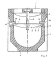
- the channel body 1 has a generally U-shaped channel body 1 with vertical side walls 3 made of a suitable material, preferably polyester concrete.
- the channel body consists of length sections which can be joined together by means of tongue and groove connections 3.
- a cover 7 is placed on contact surfaces 5 of the channel body, which, as shown, e.g. can have the shape of an inlet grate.
- a two-armed bolt 11 is rotatably supported by means of a screw bolt 9 which can be actuated from the top thereof, so that after the cover 7 has been put on, it can be rotated into the bolt position shown in the drawing, in which its ends have a projection 2a or Reach under 2b of a latch holder 4a or 4b.
- the bolt 11 is in threaded engagement with the screw bolt 9, so that after reaching the position shown, it can be clamped against the stop surface 8 by further turning the screw bolt 9.
- the Reigelhalter 4a shown on the left in FIG. 1 has the shape of a plug made of plastic or metal and is subsequently pushed into a recess formed during the shaping of the channel body 1 from the outside and, if appropriate, glued in place.
- the projection 2a has the shape of a tongue which is formed in one piece on the stopper 4a.
- the bar holder 4b shown on the right in FIG. 1b consists of two parts, namely a plug 13 made of plastic or metal, which can also be inserted into the recess from the outside, on which the projection 2b is formed, and a plug 15 which can be pressed in from the inside and with which the plug 13 is wedged into the recess.
- This inner plug 15 can have a recess 16 for attaching a tool in order to subsequently pull the plug 15 out again, for example if the plug 13 is to be replaced when a projection 2b breaks.
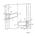
- Fig. 2 shows a schematic plan view of the designs of Fig. 1 and at the same time two different possibilities for the design of the bolt 11.
- a bolt 11 is shown in connection with the bolt holder 4a, the length of which is somewhat greater than the clear width of the channel body 1, so that the bolt 11 in its end position engaging under the projection 2a lies against the side wall of the channel body 1 and is somewhat oblique to the channel longitudinal axis.
- the end face 11 ⁇ of the bolt can be beveled accordingly.
- the corresponding gutter brackets 4a in the two side walls must be offset relative to one another and against the screw bolt 9 in the longitudinal direction of the gutter.
- the bolt 11 is somewhat shorter than the inside width of the channel body, so that the bolt can be pivoted into the position perpendicular to the longitudinal axis of the channel. A further pivoting clockwise is prevented by a stop 14 provided on the underside of the projection 2b.
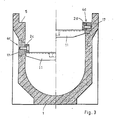
- Fig. 3 shows in the left half an embodiment in which the latch holder 4c one inserted from the outside into the recess of the gutter side wall or in the molding with embedded plug 17, which is flush with the inner wall of the gutter and subsequently a projection 2c-forming bolt engagement part is screwed, the part required for the screw connection, for example a threaded bushing or a threaded pin in which plugs 17 made of plastic can be embedded.
- the latch holder part forming the projection 2c can e.g. preferably consist of metal.
- a bar holder 4d is shown, which largely corresponds in structure to the bar holder 4c, but is inserted into a recess in the channel side wall, which is open to the bearing surface 5 and directly adjoins it.
- this has the advantage that the relatively thin side wall of the channel body 1 need not be weakened and that on the other hand the bolt 11 carrying the bolt 11 can be made relatively short.
- it is advisable to shape the anchoring part 17, for which this can be provided with concrete anchors.
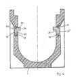
- a latch holder 4e which consists of two parts, namely a box-shaped anchoring part 19 already embedded in the channel body 5 during the formation thereof and a latch engagement part 20 subsequently inserted in this, which has the projection that can be gripped by the latch 2e wears.
- the bolt engagement part 20 is latched into the anchoring part 19 and held by means of a snap connection.
- the anchoring part 19 has a threshold 21 in the lower region, which is positively engaged behind by a corresponding projection of the bolt engagement part 20, while an elastic catch 22 is provided at the top, which snaps into a corresponding notch of the bolt engagement part 20.
- this can also be composed of two parts 19 ⁇ , 19 ⁇ , as shown for the bolt holder 4f in the right half of FIG. 4, which are put together before embedding in the channel body 1.
- Another design not shown, has a box-shaped anchoring part, which, however, has no partition.
- the latch engagement part containing the projection can be inserted from the outside and locked in some way.
- Anchoring parts are also conceivable into which the latch holder part is inserted from the inside and then locked upwards. Such bar holder parts can be replaced later if necessary.
Landscapes
- Engineering & Computer Science (AREA)
- Civil Engineering (AREA)
- Life Sciences & Earth Sciences (AREA)
- Structural Engineering (AREA)
- Paleontology (AREA)
- Environmental & Geological Engineering (AREA)
- General Life Sciences & Earth Sciences (AREA)
- Mining & Mineral Resources (AREA)
- General Engineering & Computer Science (AREA)
- Water Supply & Treatment (AREA)
- Health & Medical Sciences (AREA)
- Public Health (AREA)
- Hydrology & Water Resources (AREA)
- Architecture (AREA)
- Sewage (AREA)
Applications Claiming Priority (2)
| Application Number | Priority Date | Filing Date | Title |
|---|---|---|---|
| DE3618696 | 1986-06-04 | ||
| DE19863618696 DE3618696A1 (de) | 1986-06-04 | 1986-06-04 | Entwaesserungsrinne |
Publications (2)
| Publication Number | Publication Date |
|---|---|
| EP0248430A2 true EP0248430A2 (fr) | 1987-12-09 |
| EP0248430A3 EP0248430A3 (fr) | 1988-01-20 |
Family
ID=6302216
Family Applications (1)
| Application Number | Title | Priority Date | Filing Date |
|---|---|---|---|
| EP87108106A Withdrawn EP0248430A3 (fr) | 1986-06-04 | 1987-06-04 | Caniveau |
Country Status (2)
| Country | Link |
|---|---|
| EP (1) | EP0248430A3 (fr) |
| DE (1) | DE3618696A1 (fr) |
Cited By (6)
| Publication number | Priority date | Publication date | Assignee | Title |
|---|---|---|---|---|
| GB2220965A (en) * | 1988-07-16 | 1990-01-24 | Dow Mac Concrete Ltd | Drainage channel |
| US4935129A (en) * | 1989-03-20 | 1990-06-19 | Wang Kung Hsi | Closure device for a scupper drain |
| GB2297780A (en) * | 1995-02-07 | 1996-08-14 | Al Essa Adel Husain | Manhole and drainage gullies |
| GB2418446A (en) * | 2004-09-22 | 2006-03-29 | Kevin Patrick Mcsweeney | Manhole cover |
| EP3379000A1 (fr) * | 2017-03-23 | 2018-09-26 | Anand Belhe | Ensemble de drainage |
| EP3680407A1 (fr) * | 2019-01-10 | 2020-07-15 | ACO Severin Ahlmann GmbH & Co. KG | Élément d'insertion et avaloir |
Families Citing this family (1)
| Publication number | Priority date | Publication date | Assignee | Title |
|---|---|---|---|---|
| DE20111637U1 (de) | 2001-07-14 | 2001-12-20 | Hauraton Betonwarenfabrik GmbH & Co KG, 76437 Rastatt | Bodenrinne |
Family Cites Families (4)
| Publication number | Priority date | Publication date | Assignee | Title |
|---|---|---|---|---|
| FR369002A (fr) * | 1906-08-18 | 1906-12-27 | Wilhelm Felderbauer | Couvercle se fermant à la main ou au moyen d'une clef pour regards de caves, etc. |
| GB913267A (en) * | 1959-07-09 | 1962-12-19 | Edwin Du Guesclin Harrison | A device for draining water from flat surfaces such as roofs |
| DE8136295U1 (de) * | 1981-12-12 | 1982-04-22 | ACO Severin Ahlmann GmbH & Co KG, 2370 Rendsburg | Entwaesserungsrinne mit abdeckung |
| DE8333233U1 (de) * | 1982-11-23 | 1984-02-16 | Poly Bauelemente AG, Adliswil | Entwaesserungsrinne |
-
1986
- 1986-06-04 DE DE19863618696 patent/DE3618696A1/de not_active Withdrawn
-
1987
- 1987-06-04 EP EP87108106A patent/EP0248430A3/fr not_active Withdrawn
Cited By (7)
| Publication number | Priority date | Publication date | Assignee | Title |
|---|---|---|---|---|
| GB2220965A (en) * | 1988-07-16 | 1990-01-24 | Dow Mac Concrete Ltd | Drainage channel |
| US4935129A (en) * | 1989-03-20 | 1990-06-19 | Wang Kung Hsi | Closure device for a scupper drain |
| GB2297780A (en) * | 1995-02-07 | 1996-08-14 | Al Essa Adel Husain | Manhole and drainage gullies |
| GB2418446A (en) * | 2004-09-22 | 2006-03-29 | Kevin Patrick Mcsweeney | Manhole cover |
| GB2418446B (en) * | 2004-09-22 | 2010-06-02 | Kevin Patrick Mcsweeney | Cover |
| EP3379000A1 (fr) * | 2017-03-23 | 2018-09-26 | Anand Belhe | Ensemble de drainage |
| EP3680407A1 (fr) * | 2019-01-10 | 2020-07-15 | ACO Severin Ahlmann GmbH & Co. KG | Élément d'insertion et avaloir |
Also Published As
| Publication number | Publication date |
|---|---|
| DE3618696A1 (de) | 1987-12-10 |
| EP0248430A3 (fr) | 1988-01-20 |
Similar Documents
| Publication | Publication Date | Title |
|---|---|---|
| EP0220389A2 (fr) | Panneau pour couvrir les murs ou les plafonds | |
| EP0601445A1 (fr) | Dispositif de drainage superficiel | |
| DE3781001T2 (de) | Adaptertraeger fuer elektrogeraete. | |
| EP0081741A1 (fr) | Caniveau d'écoulement avec dispositif de recouvrement | |
| CH649802A5 (en) | Panel-securing means for facade or roof structures | |
| DE3902399A1 (de) | Zierleistenhalter | |
| CH644178A5 (de) | Vorrichtung zum verbinden von schaltafeln, insbesondere im bereich von abstufungen eines bauwerkes. | |
| EP0248430A2 (fr) | Caniveau | |
| DE2460867C3 (de) | Vorrichtung zum Verbinden von Schalungselementen | |
| DE2620522C3 (de) | Klemmvorrichtung für einen Schalungszuganker | |
| DE3400038A1 (de) | Extrudierter abdeckstreifen fuer kraftfahrzeugkarosserien und extruderkopf zur herstellung eines solchen abdeckstreifens | |
| DE3038019C2 (de) | Rasterdecke | |
| DE69516575T2 (de) | Befestigungselement für Kabel, Rohre oder dergleichen | |
| DE1908567A1 (de) | Kombinierte Form- und Verglasungsleiste als Profilstab insbesondere zum Halten einer Glasscheibe vorzugsweise an einem Rahmen | |
| DE9205273U1 (de) | Befestigungselement zur verdeckten Halterung | |
| DE8235545U1 (de) | Vorrichtung zum verwahren von verbindungseisen | |
| DE3409772A1 (de) | Mastfussanordnung fuer ein segelbrett | |
| DE3490325T1 (de) | Scheibenwischer mit Wischergelenkachse am Arm mit Querverriegelung | |
| DE8535142U1 (de) | Ausziehtisch | |
| DE9016592U1 (de) | Geradverbinder, insbesondere aus Kunststoff, zur Verbindung von hohlen Abstandsprofilen und hohlen Sprossenprofilen eines Mehrscheibenisolierglases | |
| DE69413424T2 (de) | Gussform zum eingraben von rohren | |
| DE7025049U (de) | Verbindungsorgane zur befestigung eines blendrahmens an einer mauerzange. | |
| EP0603559A1 (fr) | Attelage de remorque amovible | |
| DE8902526U1 (de) | Haltevorrichtung für Pfosten von Geländern | |
| EP0322751B1 (fr) | Dispositif à incorporer dans un coffrage pour éléments en béton |
Legal Events
| Date | Code | Title | Description |
|---|---|---|---|
| PUAI | Public reference made under article 153(3) epc to a published international application that has entered the european phase |
Free format text: ORIGINAL CODE: 0009012 |
|
| PUAL | Search report despatched |
Free format text: ORIGINAL CODE: 0009013 |
|
| AK | Designated contracting states |
Kind code of ref document: A2 Designated state(s): AT BE DE FR IT LU NL |
|
| AK | Designated contracting states |
Kind code of ref document: A3 Designated state(s): AT BE DE FR IT LU NL |
|
| STAA | Information on the status of an ep patent application or granted ep patent |
Free format text: STATUS: THE APPLICATION IS DEEMED TO BE WITHDRAWN |
|
| 18D | Application deemed to be withdrawn |
Effective date: 19880721 |
|
| RIN1 | Information on inventor provided before grant (corrected) |
Inventor name: KUNZ, DIETER, DIPL.-ING. Inventor name: FUCHS, ALFRED, DIPL.-ING. |