EP3680407A1 - Élément d'insertion et avaloir - Google Patents
Élément d'insertion et avaloir Download PDFInfo
- Publication number
- EP3680407A1 EP3680407A1 EP20150938.7A EP20150938A EP3680407A1 EP 3680407 A1 EP3680407 A1 EP 3680407A1 EP 20150938 A EP20150938 A EP 20150938A EP 3680407 A1 EP3680407 A1 EP 3680407A1
- Authority
- EP
- European Patent Office
- Prior art keywords
- insert element
- insert
- collar
- support surface
- drain
- Prior art date
- Legal status (The legal status is an assumption and is not a legal conclusion. Google has not performed a legal analysis and makes no representation as to the accuracy of the status listed.)
- Pending
Links
Images



Classifications
-
- E—FIXED CONSTRUCTIONS
- E03—WATER SUPPLY; SEWERAGE
- E03F—SEWERS; CESSPOOLS
- E03F5/00—Sewerage structures
- E03F5/04—Gullies inlets, road sinks, floor drains with or without odour seals or sediment traps
- E03F5/06—Gully gratings
-
- E—FIXED CONSTRUCTIONS
- E03—WATER SUPPLY; SEWERAGE
- E03F—SEWERS; CESSPOOLS
- E03F5/00—Sewerage structures
- E03F5/04—Gullies inlets, road sinks, floor drains with or without odour seals or sediment traps
- E03F5/041—Accessories therefor
-
- E—FIXED CONSTRUCTIONS
- E02—HYDRAULIC ENGINEERING; FOUNDATIONS; SOIL SHIFTING
- E02D—FOUNDATIONS; EXCAVATIONS; EMBANKMENTS; UNDERGROUND OR UNDERWATER STRUCTURES
- E02D29/00—Independent underground or underwater structures; Retaining walls
- E02D29/12—Manhole shafts; Other inspection or access chambers; Accessories therefor
- E02D29/14—Covers for manholes or the like; Frames for covers
- E02D29/1427—Locking devices
Definitions
- the invention relates to an insert element for producing a drainage object or for locking a cover on a polymer concrete body or a concrete body, for example on a yard drain or on a drainage channel, and a yard drain.
- Courtyard drains made of composite materials are known in the prior art. Furthermore, yard drains, which are composed of a modular system, are known. Such a modular system u. a. composed of a basic body, optionally a top element to adjust the yard drain to a floor level, and a cover element. The base body or the attachment element are designed to receive the cover element. For this purpose, the base body or the attachment element have cutouts which interact with a locking device of the cover element.
- Courtyard drains of the type mentioned above are produced by casting processes.
- the cutouts for the locking device are formed, for example, by slides or lost formwork, which are arranged on the base body or on the attachment element during the casting process. This can be at an upper edge of the Cut out air pockets or air bubbles. When the slider is removed, this leads to unevenness on the edge, which results in a deterioration in the locking security and visual defects.
- the invention is therefore based on the object of specifying an insert element for producing a courtyard drain, which provides a receptacle for a locking element and a support surface for a cover and enables secure locking. Furthermore, the invention is based on the object of specifying a yard drain.
- the object is achieved by an insert element, in particular for the production of a drainage object or for locking a cover on a polymer concrete body or a concrete body, for example on a yard drain or on a drainage channel which is cast with a composite material, in particular polymer concrete.
- the insert element comprises at least one recess which forms a receiving pocket for a locking element, a collar which at least partially delimits the recess and on which a support surface for a cover element is arranged such that the collar and the support surface are essentially L-shaped in cross section are, wherein the insert element on the back has at least one anchor element for positive connection with the composite material.
- the back of the insert element is to be understood as the side that faces away from the exposed surfaces in the cast or installed state of the yard drain, ie is not visible.
- the inner surfaces of the yard drain are the water-carrying surfaces and the outer surfaces of the yard drain are the surfaces facing away from the water-carrying inner surfaces.
- the insert element is placed in a bowl or in a mold before the casting process. After the composite material has hardened, the insert element is positively connected to the yard drain.
- the insert element is arranged on one of the approximately vertical inner surfaces of the yard drain and enables the preferably square-shaped cover element to be locked.
- the insert element is partially potted. I.e. the support surface and the collar of the insert element are flush with at least one inner surface of the courtyard drain.
- the anchor element is to be understood as any shape or geometry formed on the rear side of the insert element, which is suitable for establishing a sufficiently secure positive connection between the insert element and the composite material.
- the L-shaped cross section forms a step or a projection, which comprises a support surface.
- the L-shaped cross section is advantageous for casting in a step or a projection.
- the insert element means that there is no need to use slides when casting. The formation of air pockets is thus counteracted.
- the insert element provides a flat support surface and thus improves the locking element's locking security.
- the contact surface is preferably orthogonal. It is conceivable that the support surface includes an incline. The angle of inclination is between 50 ° and 150 °, in particular between 85 ° and 95 °.
- insert elements are arranged on the inner surfaces of the yard drain. It is conceivable that different embodiments of the insert element are combined with one another.
- the insert element according to the invention and the specified embodiments are not limited to use in a yard drain. Applications in other drainage devices, for example linear drainage devices, are conceivable.
- the bearing surface comprises a damper element.
- the damper element has an advantageous effect on the noise when, for example, a vehicle rolls over the yard drain and reduces the immediate load on the yard drain.
- the damper element is designed as an expression.
- the damper element is thus formed in one piece with the insert element, in particular molded or manufactured from one part. Other shapes are possible.
- the damper element can, for example, be made of an elastomer and arranged, in particular glued, on the support surface. Other materials are conceivable.
- the insert element is preferably made of plastic and / or steel and / or cast iron.
- the right material or the right material combination can be selected depending on the requirement. Wear can be counteracted by using the right material or combination of materials.
- the insert element has a plane of symmetry, the plane of symmetry being arranged essentially orthogonally to the collar and to the bearing surface.
- the plane of symmetry intersects the insert element in a central plane.
- the symmetrical structure of the insert element is advantageous for production.
- the symmetrical structure leads to improved solidification behavior if the insert element is produced, for example, by injection molding.
- Symmetrical shapes are also easier to produce than asymmetrical shapes.
- the insert element is characterized by a web which is arranged in the plane of symmetry and which connects the insert element to a further insert element, so that the insert element and the further insert element are arranged offset from one another in the longitudinal direction of the web.
- This embodiment is advantageously arranged on an edge or a step of the yard drain.
- the plane of symmetry forms the central plane of the component.
- the offset of the insert element and the further insert element in the longitudinal direction of the web includes a possible offset orthogonal to the longitudinal direction of the web.
- the further insert element advantageously has, at least in part, the features of the insert element according to the invention. However, it is not absolutely necessary that the further insert element corresponds to the insert element according to the invention.
- the further insert element in particular the geometric shape, is thus variable or adaptable.
- the further element can be adapted such that it interacts with a further locking device of the cover element.
- the web, the insert element and the further insert element are advantageously formed in one piece, in particular formed from a part or fabric. This can reduce the number of manufacturing steps.
- the web is connected at least in sections to the back of the collar, the depression and the support surface of the insert element, and on the other hand, the web is connected at least in sections to the back of the recess and the collar of the other insertion element.
- the web is connected to the insert element and the further insert element over the largest possible area. This has an advantageous effect on the stability of the component.
- the at least one anchor element of the insert element and the further insert element are designed as at least one cylindrical pin, strut or hook, the pins, struts or hooks extending from the rear of the collar of the insert element and the further insert element.
- the pins preferably extend parallel to a longitudinal axis of the web. Alternatively, other geometries are conceivable.
- the anchor elements are advantageously connected at least in sections to the web and the back of the depression. This improves the overall stability and the anchoring property. It is conceivable that the anchor elements are connected to the web over their entire length.
- the free axial ends of the anchor elements of the insert element and the further insert element designed as cylindrical pins preferably end on the same virtual plane.
- the virtual plane is an imaginary plane in which the end faces of the free axial ends of the cylindrical anchor elements end.
- the insert element comprises at least one spring element which is arranged on the back of the insert element.
- the spring element compensates for tolerances in the manufacturing process and ensures clear positioning in the manufacturing mold.
- the spring element is preferably formed in one piece with the insert element. Other types of spring elements are possible.
- an alignment means is arranged on the rear side of the insert element, the alignment means being connected to the rear side of the insert element by the at least one spring element.
- the alignment element serves to position the insert element in the mold before and during the casting process.
- the alignment means comprises a non-rotatable, in particular T-shaped, polygonal, round, oval or egg-shaped receptacle.
- a non-rotatable, in particular T-shaped, polygonal, round, oval or egg-shaped receptacle This makes it possible to position the insert element in the mold or shell in a rotationally secure manner. This ensures that the insert element does not change its position during the casting process.
- the at least one anchor element is designed as two cross-shaped extensions which are arranged in the plane of symmetry, the extensions spanning an angle and having cylindrical elements at the free ends which are arranged orthogonally to the plane of symmetry.
- the cross-shaped cross section is advantageous for anchoring in the composite material.
- the elements arranged orthogonally to the plane of symmetry prevent the insert element from twisting during manufacture, in particular during curing.
- a reinforcing element is arranged between the back of the support surface and the back of the depression and the collar.
- the reinforcing element is advantageous for the stability of the support surface on which the cover element rests in the installed state.
- the reinforcing element is preferably arranged between the legs of the L-shaped cross section in the plane of symmetry.
- two bases are formed on the rear side of the collar, one base being arranged on the area of the collar near the bearing surface and one base on the region of the collar remote from the bearing surface, and the at least one anchor element is arranged in the bases and is vertical extends to the contact surface.
- This embodiment has the advantage that the anchor element forms the reinforcing element at the same time.
- the anchor element is preferably designed as a cylindrical pin which is arranged in the bases and extends between the bases.
- the insert element has four spring elements, two spring elements each being connected to a base and the alignment means.
- the spring elements equalize tolerances.
- a courtyard drain with an insert element is also disclosed and claimed.
- the yard drain comprises a base body, in particular a square base body, and a cover element, wherein at least one insert element is arranged, in particular cast, in the base body.
- the insert element comprises a projection, in particular a step.
- the protrusion encompasses the contact surface.
- the cover element only rests on the support surfaces which are arranged on the insert element. It is conceivable that the cover elements on several support surfaces of several insert elements, which are arranged in the yard drain.
- the yard drain comprises an attachment element which is arranged between the base body and the cover element in order to adapt the yard drain to a floor level, at least one insert element being arranged, in particular cast, in the attachment element.
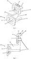
- Fig. 1 shows an exemplary embodiment of an insertion element 10.
- the insertion element 10 comprises a recess 11, a collar 12, a support surface 13, an anchor element 14 and an alignment means 18.
- the support surface 13 is arranged orthogonally on the collar 12, so that the collar 12 and the support surface 13 form an L-shaped structure in cross section.
- the recess 11 is arranged centrally in the collar 12.
- the collar 12 delimits the depression 11. In other words, the collar 12 forms an edge around the depression 11.
- the depression 11 is designed as a pocket which extends in the direction of the rear side of the insert element 10. The depression 11 protrudes behind the collar 12.
- a cover element of a courtyard drain 25 rests on the support surface 13.
- the collar 12 is flush with the composite material, for example polymer concrete.
- the recess 11 serves to receive a locking element or cooperates with a locking element which is arranged on a cover element.
- the anchor element 14 is arranged on the back of the recess 11.
- the anchor element 14 comprises extensions 20.
- the extensions 20 are cross-shaped in cross section.
- the extensions 20 have free axial ends.
- the free axial ends are designed as cylindrical elements, the cylindrical elements being arranged orthogonally to the plane of symmetry.
- the cross-shaped cross section of the extensions 20 and the cylindrical elements improve the contact and thus the anchoring in the composite material, in particular in the polymer concrete.
- the cylindrical elements counteract a rotation of the insert element 10.
- the alignment means 18 is arranged behind the rear of the collar 12.
- the alignment means 18 is designed as a T-shaped receptacle. In the installed state, the cross leg of the T-shaped receptacle is arranged at the bottom and the longitudinal leg at the top.
- the alignment means 18 is closed on the side facing the collar 12 and open on the side facing away from the collar 12.
- the alignment means 18 points to that facing away from the collar 12 Page another deepening.
- the open part is flush with an outer surface of the courtyard drain 25 formed from composite material, in particular from polymer concrete.
- the inner surfaces of the yard drain are the water-carrying surfaces and the outer surfaces of the yard drain are the surfaces facing away from the water-carrying inner surfaces.
- the T-shaped recess forms a non-rotatable receptacle, so that the insert element 10 is held in the mold at a predetermined position during the casting process.
- Other shapes that are suitable for forming a non-rotatable receptacle are conceivable.
- the spring element 17 is arranged between the alignment means 18 and the other components of the insertion element 10.
- the spring element 17 is designed as two flat springs arranged opposite one another in the plane of symmetry.
- the flat springs are flat and have a bend which is directed in the direction of the opposite flat spring.
- the two flat springs are molded in one piece with the insert element. Alternatively, other shapes and materials are conceivable.
- a flat spring is arranged on the longitudinal leg and a flat spring on the cross leg of the T-shaped receptacle.
- the flat spring arranged on the longitudinal leg is connected to the rear of the support surface 13.
- the flat spring arranged on the cross leg is connected to the anchor element 14.
- the spring element 17 compensates for tolerances during manufacture.
- the alignment means 18 can be pressed in such a way that it is flush with the outer surface of the courtyard drain 25.
- a reinforcing element 21 is arranged between the back of the support surface 13 and the back of the recess 11 and the collar 12.
- the reinforcing element 21 is connected to the rear of the support surface 13 and to the rear of the collar 12 which is closest to the support surface 13.
- the reinforcing element 21 is advantageous for the stability of the support surface 13 on which the cover element rests in the installed state.
- the Reinforcing element 21 is preferably arranged between the legs of the L-shaped cross section in the plane of symmetry.
- Fig. 2 shows an insert element 10 which, except for the spring element 17, the anchor element 14 and the reinforcing element 21, corresponds to the insert element 10 Fig. 1 corresponds.
- Two bases 22 are formed on the back of the collar 12.
- a base 22 is arranged in the area close to the support surface 13 and a base 22 in the area of the collar 12 remote from the support surface 13.
- the bases 22 are designed to receive the anchor element 14.
- the anchor element 14 is designed as a cylindrical element.
- the anchor element 14 is arranged in the bases 22.
- the anchor element 14 extends perpendicular to the support surface 13 and is connected with an end face to the back of the support surface 13.
- the anchor element 14 reinforces the support surface 13. In the exemplary embodiment described, the anchor element 14 thus simultaneously forms the reinforcement element 21.
- the spring element 17 is designed as four curved springs. Two of the curved springs are arranged opposite each other. The ends of the curved springs are each connected to the alignment means 18 and the bases 22.
- the alignment means 18 comprises a plurality of peeling ribs 26 which run essentially parallel in the direction of the bearing surface 13. The peeling ribs 26 have the task of ensuring the secure positioning of the insert element 10 in the production mold.
- the bend of the curved springs is directed in the opposite direction to the opposite curved spring.
- the oppositely arranged curved springs each extend in a plane that is parallel to the plane spanned by the support surface 13. The curved springs extend around the anchor element 14.
- the insert element 10 comprises a depression 11, a collar 12 and a support surface 13, which according to the exemplary embodiment Fig. 1 correspond.
- a support surface 13 which according to the exemplary embodiment Fig. 1 correspond.
- damper element 15 is formed as an expression on the bearing surface 13.
- the damper element 15 has an advantageous effect on the development of noise when, for example, a vehicle rolls over the yard drain 25 and reduces the immediate load on the yard drain 25.
- the further insert element 10 partially corresponds to that in FIGS Figures 3 and 4 insert element 10 shown.
- further insert element 10 has no support surface 13 and thus no damper element 15. It is possible for the further insertion element 10 ′ to have a contact surface 13 and a damper element 15.
- the insert element 10 and the further insert element 10 ' are offset in the longitudinal direction of the web 16 and in the plane of symmetry.
- the insert element 10 and the further insert element 10 ' are connected to one another by the web 16.
- the web 16 is arranged in the plane of symmetry.
- the center plane of the web 16 forms part of the plane of symmetry.
- the web 16 is connected to the back of the collar 12 and the recess 11 of the further insert element 10 '.
- the web 16 When installed (as in Fig. 5 shown), the web 16 extends in the vertical direction from the vertically arranged collar 12 of the further insert element 10 'to half of the recess 11 of the further insert element 10'. In the installed state, the web 16 extends in the horizontal direction in the direction of the outer surface of the courtyard drain 25.
- the insertion element 10 is arranged at the axial end on the upper side of the web 16 in the installed state.
- the insert element 10 is aligned in the direction of the inner surface of the yard drain 25.
- FIG. 5 The embodiment of the insert element 10 described above, which is connected to a further insert element 10 ′ by a web 16, is shown in the cast or installed state in the yard drain 25.
- the insert element 10 is shown with a section through the plane of symmetry.
- the yard drain 25 includes an opening.
- a step is arranged in the area of the opening. That in the Figures 3 and 4 The described embodiment of the insert element 10 is adapted for the positive connection with the step shown.
- the insert element 10 is potted for the positive connection in the yard drain 25.
- the collars 12 of the insert element 10 and of the further insert element 10 ′ are each flush with the inner sides of the yard drain 25.
- the contact surface 13 of the insert element 10 is flush with the yard drain 25.
- the damper element 15 is formed on the support surface 13. The damper element 15 protrudes above the bearing surface 13.
- the depressions 11 are designed to receive a locking element of a cover (not shown).
- Fig. 6 shows a basic body 23 of a yard drain 25 with four insertion elements 10 according to the Figures 1 or 2 .
- the insert elements 10 are each arranged centrally on the step on an inner surface of the yard drain 25.
- Fig. 7 is an attachment element 24 on the in Fig. 6 described basic body 23 arranged.
- the attachment element 24 is rectangular, in particular square.
- the attachment element 24 is designed such that it can be arranged on the base body 23.
- the end of the attachment element 24 directed in the direction of the base body 23 has a step which interacts positively with the step of the base body 23, so that the attachment element 24 is arranged on the base body 23 in such a way that it cannot move.
- Safe to move means that Attachment element is substantially immovable in a plane that is parallel to the plane of the contact surfaces 13 of the insert elements 10.
- the attachment element 24 comprises four side walls with outer and inner surfaces.
- the outer surfaces have a rectangular recess on three side walls.
- the recess has the function of reducing material and thus the weight.
- a circular opening is arranged on the side wall without a recess.
- a sealing ring in particular a lip seal, is arranged in the circular opening.
- the opening is designed to receive a pipe or a pipe socket.
- the attachment element can thus be connected to a drainage system.
- the attachment element 24 comprises four insertion elements 10 according to FIG Figure 1 or 2 .
- the insert elements 10 are each arranged centrally on the step on an inner surface of the attachment element 24.
- insert element 10 is cast in the yard drain 25 or that different embodiments are combined with one another. It is conceivable that the insert element 10 can be adapted to other yard processes.
Landscapes
- Health & Medical Sciences (AREA)
- Life Sciences & Earth Sciences (AREA)
- Engineering & Computer Science (AREA)
- Hydrology & Water Resources (AREA)
- Public Health (AREA)
- Water Supply & Treatment (AREA)
- Building Environments (AREA)
- Joining Of Building Structures In Genera (AREA)
Applications Claiming Priority (1)
| Application Number | Priority Date | Filing Date | Title |
|---|---|---|---|
| DE102019100469.1A DE102019100469A1 (de) | 2019-01-10 | 2019-01-10 | Einlegeelement und Hofablauf |
Publications (1)
| Publication Number | Publication Date |
|---|---|
| EP3680407A1 true EP3680407A1 (fr) | 2020-07-15 |
Family
ID=69156324
Family Applications (1)
| Application Number | Title | Priority Date | Filing Date |
|---|---|---|---|
| EP20150938.7A Pending EP3680407A1 (fr) | 2019-01-10 | 2020-01-09 | Élément d'insertion et avaloir |
Country Status (2)
| Country | Link |
|---|---|
| EP (1) | EP3680407A1 (fr) |
| DE (1) | DE102019100469A1 (fr) |
Families Citing this family (1)
| Publication number | Priority date | Publication date | Assignee | Title |
|---|---|---|---|---|
| DE102020132316A1 (de) * | 2020-12-04 | 2022-06-09 | Aco Ahlmann Se & Co. Kg | Höhenversteller |
Citations (5)
| Publication number | Priority date | Publication date | Assignee | Title |
|---|---|---|---|---|
| EP0248430A2 (fr) * | 1986-06-04 | 1987-12-09 | Passavant-Werke Ag | Caniveau |
| DE9421582U1 (de) * | 1994-01-08 | 1996-03-21 | Hauraton GmbH & Co. KG, 76437 Rastatt | Lösbare Arretierung einer auf einem Grundkörper aufliegenden Abdeckung |
| DE20010316U1 (de) * | 2000-06-08 | 2001-10-18 | Broermann, Rita, 59609 Anröchte | Rinnenelement |
| KR20100001894U (ko) * | 2008-08-13 | 2010-02-23 | 박형준 | 무소음 트랜치 커버 |
| US20140110007A1 (en) * | 2012-10-19 | 2014-04-24 | Aco Polymer Products, Inc. | Drainage channels and methods for making drainage channels |
Family Cites Families (3)
| Publication number | Priority date | Publication date | Assignee | Title |
|---|---|---|---|---|
| DE19545131C2 (de) * | 1995-12-01 | 1998-07-02 | Birco Baustoffwerk Gmbh | Abdeckrostbefestigung einer Rinne |
| DE10346586B4 (de) * | 2003-10-07 | 2006-06-01 | Aco Severin Ahlmann Gmbh & Co. Kg | Befestigungsvorrichtung |
| KR100895007B1 (ko) * | 2008-03-19 | 2009-04-24 | 주식회사 하렉스 엔지니어링 | 연결수단을 구비한 조립식 맨홀 |
-
2019
- 2019-01-10 DE DE102019100469.1A patent/DE102019100469A1/de active Pending
-
2020
- 2020-01-09 EP EP20150938.7A patent/EP3680407A1/fr active Pending
Patent Citations (5)
| Publication number | Priority date | Publication date | Assignee | Title |
|---|---|---|---|---|
| EP0248430A2 (fr) * | 1986-06-04 | 1987-12-09 | Passavant-Werke Ag | Caniveau |
| DE9421582U1 (de) * | 1994-01-08 | 1996-03-21 | Hauraton GmbH & Co. KG, 76437 Rastatt | Lösbare Arretierung einer auf einem Grundkörper aufliegenden Abdeckung |
| DE20010316U1 (de) * | 2000-06-08 | 2001-10-18 | Broermann, Rita, 59609 Anröchte | Rinnenelement |
| KR20100001894U (ko) * | 2008-08-13 | 2010-02-23 | 박형준 | 무소음 트랜치 커버 |
| US20140110007A1 (en) * | 2012-10-19 | 2014-04-24 | Aco Polymer Products, Inc. | Drainage channels and methods for making drainage channels |
Also Published As
| Publication number | Publication date |
|---|---|
| DE102019100469A1 (de) | 2020-07-16 |
Similar Documents
| Publication | Publication Date | Title |
|---|---|---|
| DE3990874C2 (de) | Selbsttragendes, miteinander zu verbindendes Schalungselement zum Gießen von Wandkonstruktionen | |
| EP2848159B1 (fr) | Poignée | |
| DE8909099U1 (de) | Anschlußschalung für aneinander anschließende Betonplatten | |
| WO1999064696A1 (fr) | Corps creux pour le deplacement de beton, en particulier dans des sols et des plafonds en beton de constructions en beton a plusieurs etages | |
| EP3680407A1 (fr) | Élément d'insertion et avaloir | |
| DE4037438A1 (de) | Transportables stahlbetonfundament fuer eine stuetze | |
| EP2716839B1 (fr) | Elément de coffrage | |
| DE202009004195U1 (de) | Bewehrungsvorrichtung zur Herstellung eines Fertigbauteils | |
| DE202015101463U1 (de) | Bausatz zur Errichtung einer Gebäudewand | |
| DE102013104405A1 (de) | Entwässerungsrinnensystem | |
| AT504110A4 (de) | Gussfreundliche schachtabdeckung mit dämpfender einlage | |
| DE102021118578A1 (de) | Zwischenrahmen für einen Hausanschluss und Baugruppe mit einer Grundplatte und mindestens zwei solchen Zwischenrahmen | |
| DE10320995A1 (de) | Stoßfugenanordnung bei einem Bauwerkteil, Betonfertigteile hierfür und Bauwerkteil mit solchen Betonfertigteilen und Stoßfugenanordnungen | |
| CH718329B1 (de) | Abschalleiste, Überdeckungsabschalung, Abschalungselement, Schalungsanordnung, Verfahren zum Aufbau einer Schalungsanordnung und Verfahren zum Herstellen einer Abschalleiste. | |
| DE3232576C2 (fr) | ||
| EP3933141B1 (fr) | Procédé pour la fabrication d'un élément en béton préfabriqué | |
| EP2000726A2 (fr) | Abattoir en béton | |
| EP2388407B1 (fr) | Cale de montage | |
| DE102012102515A1 (de) | Wandelement | |
| AT505267A1 (de) | Verbindungselement und hohlwandelement mit solchen verbindungselementen | |
| DE102007028324B4 (de) | Schacht aus Beton und Lastaufnahmeelement | |
| DE19549550C2 (de) | Transportsystem für Betonteile | |
| AT524807A2 (de) | Balkon- oder Terrassenelement mit einer Entwässerungseinrichtung, Entwässerungseinrichtung für ein solches Balkon- oder Terrassenelement sowie Herstellungsverfahren | |
| EP4311884A1 (fr) | Couvercle de regard | |
| DE102024106592A1 (de) | Fundamentstein |
Legal Events
| Date | Code | Title | Description |
|---|---|---|---|
| PUAI | Public reference made under article 153(3) epc to a published international application that has entered the european phase |
Free format text: ORIGINAL CODE: 0009012 |
|
| STAA | Information on the status of an ep patent application or granted ep patent |
Free format text: STATUS: THE APPLICATION HAS BEEN PUBLISHED |
|
| AK | Designated contracting states |
Kind code of ref document: A1 Designated state(s): AL AT BE BG CH CY CZ DE DK EE ES FI FR GB GR HR HU IE IS IT LI LT LU LV MC MK MT NL NO PL PT RO RS SE SI SK SM TR |
|
| AX | Request for extension of the european patent |
Extension state: BA ME |
|
| STAA | Information on the status of an ep patent application or granted ep patent |
Free format text: STATUS: REQUEST FOR EXAMINATION WAS MADE |
|
| 17P | Request for examination filed |
Effective date: 20201211 |
|
| RBV | Designated contracting states (corrected) |
Designated state(s): AL AT BE BG CH CY CZ DE DK EE ES FI FR GB GR HR HU IE IS IT LI LT LU LV MC MK MT NL NO PL PT RO RS SE SI SK SM TR |
|
| STAA | Information on the status of an ep patent application or granted ep patent |
Free format text: STATUS: EXAMINATION IS IN PROGRESS |
|
| 17Q | First examination report despatched |
Effective date: 20211018 |
|
| RAP3 | Party data changed (applicant data changed or rights of an application transferred) |
Owner name: ACO AHLMANN SE & CO. KG |
|
| RIN1 | Information on inventor provided before grant (corrected) |
Inventor name: MEIER, STEPHAN Inventor name: LINGNER, PAUL Inventor name: HOPPE, MARCO Inventor name: HASCHE, CHRISTIAN |