EP0248576A1 - Emballage de panneaux de fibres de verre - Google Patents
Emballage de panneaux de fibres de verre Download PDFInfo
- Publication number
- EP0248576A1 EP0248576A1 EP87304602A EP87304602A EP0248576A1 EP 0248576 A1 EP0248576 A1 EP 0248576A1 EP 87304602 A EP87304602 A EP 87304602A EP 87304602 A EP87304602 A EP 87304602A EP 0248576 A1 EP0248576 A1 EP 0248576A1
- Authority
- EP
- European Patent Office
- Prior art keywords
- compression
- stack
- batts
- batt
- compressed
- Prior art date
- Legal status (The legal status is an assumption and is not a legal conclusion. Google has not performed a legal analysis and makes no representation as to the accuracy of the status listed.)
- Granted
Links
- 239000003365 glass fiber Substances 0.000 title claims abstract description 36
- 238000004806 packaging method and process Methods 0.000 title claims description 20
- 238000007906 compression Methods 0.000 claims abstract description 290
- 230000006835 compression Effects 0.000 claims abstract description 287
- 239000000463 material Substances 0.000 claims abstract description 45
- 238000009413 insulation Methods 0.000 claims abstract description 27
- 238000011084 recovery Methods 0.000 claims abstract description 11
- 230000001737 promoting effect Effects 0.000 claims abstract description 3
- 238000000034 method Methods 0.000 claims description 23
- 230000000694 effects Effects 0.000 claims description 9
- 238000007789 sealing Methods 0.000 claims description 9
- 238000006073 displacement reaction Methods 0.000 claims description 7
- 239000002985 plastic film Substances 0.000 claims description 7
- 239000004033 plastic Substances 0.000 claims description 6
- 229920003023 plastic Polymers 0.000 claims description 6
- 238000000151 deposition Methods 0.000 claims description 2
- 210000004894 snout Anatomy 0.000 description 17
- 230000007246 mechanism Effects 0.000 description 12
- 239000005022 packaging material Substances 0.000 description 5
- 230000005540 biological transmission Effects 0.000 description 3
- 239000006260 foam Substances 0.000 description 3
- 230000000717 retained effect Effects 0.000 description 3
- 241000143973 Libytheinae Species 0.000 description 2
- 239000004698 Polyethylene Substances 0.000 description 2
- 238000010420 art technique Methods 0.000 description 2
- 238000010276 construction Methods 0.000 description 2
- 239000000835 fiber Substances 0.000 description 2
- -1 polyethylene Polymers 0.000 description 2
- 229920000573 polyethylene Polymers 0.000 description 2
- 238000012545 processing Methods 0.000 description 2
- 240000004752 Laburnum anagyroides Species 0.000 description 1
- 238000013459 approach Methods 0.000 description 1
- 239000005391 art glass Substances 0.000 description 1
- 230000015572 biosynthetic process Effects 0.000 description 1
- 230000009931 harmful effect Effects 0.000 description 1
- 238000003780 insertion Methods 0.000 description 1
- 230000037431 insertion Effects 0.000 description 1
- 239000002184 metal Substances 0.000 description 1
- 238000012986 modification Methods 0.000 description 1
- 230000004048 modification Effects 0.000 description 1
- 229920000915 polyvinyl chloride Polymers 0.000 description 1
- 239000004800 polyvinyl chloride Substances 0.000 description 1
- 230000003014 reinforcing effect Effects 0.000 description 1
- 238000007493 shaping process Methods 0.000 description 1
- 238000010008 shearing Methods 0.000 description 1
- 229920001169 thermoplastic Polymers 0.000 description 1
- 239000004416 thermosoftening plastic Substances 0.000 description 1
- 238000012546 transfer Methods 0.000 description 1
Images





Classifications
-
- B—PERFORMING OPERATIONS; TRANSPORTING
- B65—CONVEYING; PACKING; STORING; HANDLING THIN OR FILAMENTARY MATERIAL
- B65B—MACHINES, APPARATUS OR DEVICES FOR, OR METHODS OF, PACKAGING ARTICLES OR MATERIALS; UNPACKING
- B65B63/00—Auxiliary devices, not otherwise provided for, for operating on articles or materials to be packaged
- B65B63/02—Auxiliary devices, not otherwise provided for, for operating on articles or materials to be packaged for compressing or compacting articles or materials prior to wrapping or insertion in containers or receptacles
Definitions
- the present invention relates to a method of and apparatus for applying a covering to glass fibre batts.
- Glass fibre insulation batts are conventionally sold in prepackaged and compressed stacks of batts, which are compressed at compression ratios of between 3:l and 5:l and contained in plastic bags, which retain the batts in their compressed state.
- the aforementioned prior patents each describe an apparatus in which batts are transported downwardly through a batt stacking space on a platen, on which the batts are assembled into a stack by dropping the batts vertically from a batt accumulator mechanism overlying the batt stacking space.
- the platen approaches the bottom of a batt stacking space, the platen is withdrawn laterally from the space and recycled to the top of the space, which it reenters and down which it then travels to compress the batts in a compression space.
- the thus-compressed batts are laterally ejected in their compressed state through a snout into a bag, as described above.
- the stacks of batts are compressed between flat compression surfaces prior to being ejected through the snout.
- the batts expand somewhat within their bag after leaving the snout and consequently the finished bag of batts assumes a configuration having slightly convex top and bottom faces, the batts being subjected to an initial compression between the compression plates and, subsequently, portions of the batts being subjected to additional compression or slight expansion at the bagging stage.
- the compression of the batts is necessarily limited in practice, and in accordance with the numbers and sizes of the batts, in order to ensure that when the batts are eventually released from their package at their point of use and thus allowed to expand from their compressed state, the batts can expand sufficiently to regain or recover sufficient of their original thickness, i.e. their thickness prior to compression.
- the compression ratio employed for the compression of the batts between the compression plates has hitherto been limited in order to avoid or at least reduce damage to the batts and to permit sufficient recovery of the batts when they are unpackaged. More particularly, it has hitherto been conventional to provide bags of glass fibre insulation batts in which the batts are compressed with the package compression ratio of 3:l to 5:l, as indicated above. Consequently, the number of batts which can be accommodated in a bag of a given size is correspondingly limited.
- the bagged or packaged stacks of batts are further compressed into bales to provide an overall compression ratio of between 6:l and ll:l, which of course necessitate a separate operation and thus increases costs and processing times.
- a further disadvantage of the above-described prior art glass fibre insulation batt packaging or bagging machines was that the throughput of such machines, i.e. the initial bagging of the batts, was restricted to an undesirably low rate. More particularly, it was found in practice that as the throughput of such machines was increased, problems arising from misalignment of the batts in the batt compression space and from increased vibration, and consequential wear, which occurred as a result of the correspondingly higher speeds of operation of the machines, and thus the reliability of the operation of these machines at these higher speeds, effectively limited the maximum speeds at which the machines could be operated. The need for increased productivity indicated that such speed limitations should be overcome.
- United States Patent 2,765,838, issued October 9, l956 to G. H. Brown teaches apparatus for packaging a group of fibrous mats or batts, made for example of glass fibre, by placing a stack of the fibrous mats upon a first sheet of paper on a conveyor flight supported by a reinforcing plate, placing a further sheet of paper on the top of the stack of fibrous mats and then compressing the stack by downward movement of a platen against the top of the stack, the edge portions of the sheets of paper being folded and adhered together to enclose the compressed stack.
- flat surfaces are employed for compressing the product and no information is provided as to the compression ratios employed.
- the inventor has now found that a substantial improvement in the packaging of glass fibre insulation batts is obtained by employing, in place of the flat compression surfaces employed by the prior art, a pair of compression surfaces which are recessed, preferably in a curved manner, so as to at least approximate in a complimentary manner to the convexly curved shapes of the corresponding surfaces of the finished batt package or its bag.
- compression ratio means the total nominal thickness of the batts, divided by the compressed height of the batts, and the nominal thickness is the thickness which the batts are inclined to assume when released from their package, and which is less than the thickness of the batts prior to the packaging thereof.
- the "compressed height of the batts” refers to the height of the finished package, if the compression ratio referred to is that of the package, and to the spacing betweeen the flat upper and lower compression surfaces, when the stack is fully compressed therebetween, if the compression ratio referred to is that which is produced by the machine.
- the compressed height of the batts in the package or bag is greater than the compressed height corresponding to the spacing of the compression surfaces when the stack is fully compressed therebetween and, therefore, the compression ratio in the latter case is greater than the package compression ratio.
- the compression ratio in the machine required to produce a predetermined package compression ratio is less than that required to produce the same predetermined package compression ratio employing flat compression surfaces instead of the presently proposed recessed compression surfaces.
- a method of packaging glass fibre insulation batts by compressing a stack of the batts and providing a containment of plastic sheet material around the compressed stack, the improvement comprising the step of employing opposed concave compression surfaces to effect the compression of the stack, whereby the compression of the stack can be substantially enhanced while maintaining satisfactory thickness recovery of the batts upon release from the bag.
- the convex compression surfaces taught by the present invention provide the advantage that they enable more batt material, i.e. a larger number of batts and/or batts of a greater thickness, to be accommodated in the package, than was possible with the prior art flat compression plates previously employed for compressing the batts.
- While the present method may be employed in conjunction with a snout through which the compressed stack of batts is rounded into a bag, as in the above-described prior art methods and machines, this requires the stack to be compressed by an amount, equal to the thickness of the walls of the snout, which is greater than would otherwise be necessary. It is therefore preferred to avoid the use of a snout by forming the covering around the stack while the stack is compressed between the compression surfaces and then releasing the compressed stack to allow the batts to expand against the covering. This can be achieved by locating upper and lower sheets of flexible material between the stack and the compression surfaces prior to the compression of the stack and sealing together edge portions of these sheets to form the covering while the stack is held in compression by the compression surfaces.
- the present method also provides the advantage that the above-mentioned second compression of the batts by compressing groups of bags or batt packages into bales, and the consequential substantial damage to the batts which is found to occur in practice during such second compression may be eliminated entirely by simply unitizing batt packages, formed in accordance with the present invention, into bales without compression of the packages.
- the present invention further provides, in apparatus for packaging batts of glass fibre material comprising a pair of compression members means for effecting relative displacement of the compression surfaces to compress a stack of glass fiber batts therebetween and means for providing a covering around the compressed stack to retain the batts in a compressed state, the improvement comprising opposed concave surfaces on the compression members for forming correspondingly convex surfaces at opposite ends of the stack during the compression thereof, thereby facilitating compression of the stack counteracting damage to the batts during the compression thereof and promoting satisfactory recovery of the batts upon release from the covering.
- the apparatus may include a vertically elongate batt stacking space, means for depositing the batts in succession into the batt stacking space to form the stack of the batts therein, and means for providing a covering of flexible sheet material around the compressed stack to maintain the stack in a compressed state upon removal of the compressed and covered stack from the apparatus.
- Such shaping of the stack counteracts damage to the edges of the uppermost and lowermost batt upon expansion of the stack against its covering, as described above, and thus enables satisfactory recovery of the batts when they are eventually released from their covering and allowed to expand freely.
- the compression surfaces are cylindrically curved with a radius of curvature of l/2W to 3W, preferably 5/8W, where W is the width of the batts.
- this radius of curvature is preferably about 9 l/2 inches for batts having a width of l5 inches, and about l8 inches for batts having a width of 23 inches.
- concave compression surfaces are preferably curved, some advantage over prior art flat compression surfaces may be obtained by forming the compression surfaces with recesses having flat inclined sides and a curved or flat bottom.
- the shapes of the top and bottom surfaces of the compressed stack of insulation batts are preferably formed so as to correspond substantially to the shapes of the corresponding surfaces of the finished package, i.e. of the shape which will be assumed by the compressed batts in their retaining covering when released from the apparatus.
- a batt support member is mounted for horizontal displacement into and from the batt stacking space at a location near the bottom of the batt stacking space and above the lower compression means.
- the above support means is withdrawn from the batt stacking space at this location, upon displacement of the batts forward member into the location, in order to transverse the stack of batts from the batt support means to the batt support member.
- the upper compression surface is then displaced downwardly against the top of the stack to effect the compression of the stack in a single stroke without relaxation, in order to minimize fibre breakage.
- edge portions of the covering material sheets are sealed together at opposite sides of the compressed stack.
- the covering is preferably formed around the product in this way, in contrast to prior art techniques, in which the glass fibre insulation batts must be over-compressed and rammed through snouts into prepared bays, both of which operations involve greater damage to the product.
- bagging of the batts may in suitable cases be effected by ramming the compressed batts through a snout into bags.
- an auxiliary compression means for compressing the first of the stack in the batt stacking space and for supporting the remainder of the stack for compression of the remainder of the stack by the upper compression means.
- the auxiliary compression means is removed from the stack, which is thus united.
- this auxiliary compression means enables the overall height of the apparatus to be reduced.
- FIG. l there is indicated generally by reference numeral l0 a glass fiber insulation batt compression machine according to the first embodiment of the invention.
- the machine l0 comprises a machine bed indicated generally by reference numeral ll on which a tower indicated generally by reference numeral l2 is supported and braced by struts l4.
- the tower l2 is in the form of a framework of metal beams, comprising four vertical posts l6 which are interconnected by horizontal cross-beams l7, not all of which are shown.
- a first platform indicated generally by reference numeral l8 is fixed relative to the tower l2 and carries an upper sheet feed mechanism indicated generally by reference numeral 20 (Figure 4A), which comprises a pneumatic ram 22 carrying, on its piston, gripper jaws 24 for drawing the leading edge of a sheet material 26 from a supply roll 28 and a cutter 25 for cutting transversely across the sheet material 26.
- Figure 4A an upper sheet feed mechanism indicated generally by reference numeral 20 ( Figure 4A), which comprises a pneumatic ram 22 carrying, on its piston, gripper jaws 24 for drawing the leading edge of a sheet material 26 from a supply roll 28 and a cutter 25 for cutting transversely across the sheet material 26.
- the batt packaging machine has a lower sheet feed mechanism indicated generally by reference numeral 30, which comprises a pneumatic ram 32 having jaws 33 for gripping and advancing the leading edge of a sheet material 35 from a supply roll 38 and a cutter 36 for cutting across the sheet material 35 materials.
- the sheet materials 26 and 35 are polyethylene sheets.
- a carriage indicated generally by reference numeral 39 is moveable vertically along the tower l2.
- the carriage 39 carries a pneumatic ram 34, which is operable to effect horizontal displacement of an intermediate compression plate 36.
- the carriage 39 can be moved to and fro vertically along the tower l2 by a drive mechanism comprising a drive motor 38 connected by a chain and pulley drive transmission indicated generally by reference numeral 40 to the carriage 39.
- a further pneumatic ram 42 is secured to the tower l2 and serves to effect horizontal extension and retraction of a horizontal support plate 44.
- a further carriage is moveable vertically to and fro between an upper position in which it is shown in Figure 4A and a lower position in which it is shown in Figure 4C, by means of a drive motor 48 and a chain and pulley drive transmission indicated generally by reference numeral 50.
- the carriage 46 carries a pneumatic ram 52 which is operable to effect horizontal extension and retraction of an upper batt compression member indicated generally by reference numeral 54.
- the lower batt compression member 56 is vertically displaceable, through a relatively short distance, from a lowermost position in which it is shown in Figure 4A to an uppermost position in which it is shown in Figure 4E by means of a drive mechanism comprising a drive motor and a chain and pulley mechanism indicated generally by reference numeral 58.
- the underside of the upper batt compression member 54 is formed by the cylindrically curved, downwardly concave compression surface of a compression plate 58, and the upper surface of the lower batt compression member 56 is formed by the cylindrically curved, upwardly concave compression surface of a compression plate 60.
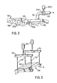
- the upper batt compression member 54 is a hollow box having opposite flat side walls 55 ( Figure 2), formed with suction openings 57a, and having a top surface formed by a plate 62.
- the interior of this box communicates through a hollow support member 59 and a duct 6l fixed to the hollow support member 59, a gate valve 63a operated by a pneumatic cylinder 63b and a flexible duct 65 with a suction fan 67 to enable air to be sucked in through openings 57b in the compression plate 58.
- a batt accumulator which serves to accumulate insulation batts delivered thereto by an upwardly inclined conveyor indicated generally by reference numeral 66 in Figure l and deposited into the accumulator 64 by a batt loader indicated generally by reference numeral 68.
- the accumulator 64 and the batt loader 68 are of conventional construction, which is well known to those skilled in the art, and which therefore will not be described in further detail herein, except to mention that the bottom of the accumulator 64 is provided with a pair of accumulator doors 70 which are pivotable between a closed position, in which they are shown in Figure 4A, and an open position, in which they are shown in Figure 4B, by means of pneumatic piston and cylinder devices 72. These doors 70, when in their closed position, serve to retain batts in the accumulator 64 and, when opened, release the batts so that the batts are able to fall into the stacking space 55.
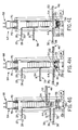
- the lower batt compression member 56 is in the form of an elongate hollow box which, as shown in Figure 3, is supported at opposite ends on a pair of horizontal lower support beams 7l, suspended by vertical bars 73 from upper horizontal support beams 75.
- a pair of pneumatic cylinders 77 which are mounted on the tower l2, are operable to raise and lower the beams 7l and 73 and, therewith, the lower batt compression therewith, the lower batt compression member 56.
- the cycle of operation of the machine l0 is as follows.
- the upper batt compression member 54 is correspondingly displaced downwardly through the compression space 55 and, during this downward movement of the upper batt compression member 54, the accumulator doors 70 are opened, as shown in Figure 4B, to deposit glass fiber insulation batts, indicated by reference numeral 74, onto the flat uppermost support plate 62 forming the top of the upper batt compression member 54.
- top plate 62 there is formed on the top plate 62 a first portion of a stack of batts.
- the upper batt compression member 54 descends to its lowermost position and, the pneumatic ram 52 is then operated to retract the upper batt compression member 54 and, simultaneously, the pneumatic ram 42 is operated to extend the support plate 44 horizontally into the stacking space 54 below the batts therein, so that the first portion of the stack of batts is thereby transferred from the top plate 62 of the upper batt compression member 54 to the top of the support plate 44, as illustrated in Figure 4C.
- the carriage 46 is then displaced upwardly, as shown in Figure 4D, to return to its uppermost position, as shown in Figure 4E.
- the carriage 32 is raised by the motor 38 to the level of the top of the stacking space 55, the pneumatic ram 34 is operated to extend the intermediate compression plate 36 into the stacking space 55 and the accumulator doors 70 open to deposit additional batts onto the intermediate compression plate 36, as also shown in Figure 4D, the motor 38 being energized to cause the carriage 32 and therewith the intermediate compression plate 36 to be displaced downwardly.
- the accumulator doors 70 are again closed and the pneumatic ram 32 is operated as indicated by an arrow, to advance the sheet material 35 across the compression space 55 between the extended support plate 44 and the lower batt compression member 56 and the cutter 26 is operated to provide a cut lower sheet 37 on the lower compression plate 60.
- the lower batt compression member 56 is raised by operation of the pneumatic cylinders 77 from its lowermost position to its uppermost position, in which it more closely underlies the support plate 44, so as to minimize the distance between the bottom of the compressed batts and the compression surface of the lower compression member 56 and, thus, to counteract a misalignment of the compressed batts as the support plate 44 is retracted into its withdrawn position, in which it is shown in Figure 4F, to allow the compressed batts to expand downwardly onto the lower batt compression member 56.
- the pneumatic ram 22 is operated to extend the gripper jaws 24 across the stacking space 55 and, the cutter 25 is operated to provide an upper cut sheet 4l of flexible material between the uppermost batt in the stacking space 55 and the underside of the upper batt compression member 54, which is again extended into the top of the stacking space 55 by operation of the pneumatic ram 52 as shown in Figure 4F.
- the lower batt compression member 56 is lowered from its uppermost position, in which it is shown in Figure 4E, to an intermediate position, in which it is supported by lock bars l80 as shown in Figure 4F.
- the upper cut sheet 4l of material By the application of suction from the interior of the upper batt compression member 54 through the openings 57b in the compression plate 58, the upper cut sheet 4l of material, which at this time is released by the gripper jaws 24, is drawn against the curved downwardly facing surface of the compression plate 58 and thereby retained against that surface while opposite edge portions of the sheet 4l are retained against the side walls 55 by suction through the openings 57a.
- the pneumatic ram 22 is then operated to retract the gripper jaws 24 from the stacking space 55, and the motor 48 is operated to cause the carriage 46 to descend and, thus, to cause the upper batt compression member 54 to descend through the batt stacking space 55.
- the pneumatic ram 34 is operated to retract the intermediate compression plate 36, as shown in Figure 4G, so that the batts between the upper and lower batt compression members 54 and 56 are united into a single stack with the lower batt compression member 56 still in its intermediate position.
- the upper batt compression member 54 continues to descend until is reaches its lowermost position, as shown in Figure 4H, and the lower batt compression number 56 is moved upwardly, until the compression of the batts has been completed.
- Heat seal bars 78 at opposite sides of the compressed stack of batts are then operated to clamp together and to seal together marginal edge portions of the upper and lower sheets of packaging material to form a covering around the compressed stack of batts.
- the upper batt compression member 54 is then raised and the lock bars l80 are withdrawn from the lower batt compression member 56, which is lowered into its lowermost position, in which it is shown in Figure 4I, in order to release the pressure exerted thereby on the stack of batts. Consequently, the batts are thereby allowed to expand within their covering by an amount which is restricted by the covering, so that the batts are then maintained in a state of compression by the covering.
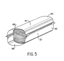
- the compressed and covered stack of batts which is indicated generally by reference numeral 80 in Figure 5, is then ejected from the machine l0 by the operation of a ram l8l perpendicular to the plane of Figures 4A to 4H, and the next cycle of the operation of the machine, starting from the state shown in Figure 4C, is initiated.
- the compressed stack of batts is retained in its compressed state by the elongate seals, one of which is shown and indicated by reference numeral 84, connecting together the marginal edge portions of the upper and lower cut sheets 37 and 4l of packaging material, which project beyond opposite ends of the stack to form free end portions 86.
- the height of the stacking space 55 By compressing initially a first portion of the total batt content of a package and then subsequently compressing the remainder of the batts to be included in the same package, the height of the stacking space 55, and thus the height of the tower l2, can be reduced as compared to what would be required to compress the entire stack of batts in a single stroke of the upper batt compression member 54.
- Figures 6A and 6B diagrammatically illustrate a modification of the machine of Figure l0.
- the modified machine has, instead of a single upper batt compression member 54, two upper batt compression members, indicated by reference numerals l54a and l54b, respectively, which are displaceable to and from the stacking space 55 by respective pneumatic cylinders l52a and l52b, mounted on carriages indicated generally by reference numerals l46a and l46b, respectively.
- the carriages l46a and l46b are displaceable to and fro vertically by chain and sprocket drive transmissions indicated generally by reference numerals l40a and l40b, driven by respective motors (not shown).
- Upper and lower sheet feed mechanisms l20a and l30a are, in this case, arranged to feed the sheet material along the length of the upper and lower compression members, rather than transversely, i.e. in the direction of their widths as is the case with the machine l0 of Figures l and 2.
- a support plate l36 is displaceable to and fro by means of a pneumatic ram l34 in the same direction as the sheet material, i.e. longitudinally of the upper and lower batt compression members.
- the upper and lower sheet feed mechanisms l20a and l30a and the support plate l36 do not obstruct the vertical displacement of the carriages l46a and l46b.
- the upper and lower batt compression members l54a and l54b are each provided with an auxiliary support plate l55a and l55b, respectively, which are each spaced above the upper batt compression members l54a and l54b by a gap which, in the case of the support plate l55a is laterally open to the left as viewed in Figure 4A and, in the case of the support plate l55b is open to the right, also as shown in Figure 4A, to accommodate the support plate l36 and to allow the upper batt compression members l54a and l54b to be extended into and retracted from the stacking space 55 while the upper plate l36 is in its extended position, i.e. while the support plate l36 is extended into the stacking space 55.
- FIG. 4A and 4B For convenience of illustration, a pneumatic ram l58 has been shown in Figures 4A and 4B for raising and lowering the lower batt compression member l56.
- Figures 4A and 4B show a ram l82 which can be extended and retracted longitudinally of the batt compression members for ejecting the batt packages from this machine. It will be appreciated that other types of drives, e.g. chain and sprocket drives, may be utilized instead of the rams l58 and l82.
- the modified machine further incorporates a batt accumulator indicated generally by reference numeral l64, which like the batt accumulator 64 of Figures l and 2 is of conventional construction, and sealing jaws l78 corresponding to the sealing jaws 78 of the machine l0.
- a batt accumulator indicated generally by reference numeral l64 which like the batt accumulator 64 of Figures l and 2 is of conventional construction, and sealing jaws l78 corresponding to the sealing jaws 78 of the machine l0.
- batts are released by the batt accumulator l64 to fall into the stacking space 55 and, thereby, to form stacks on the uppermost surfaces of the supports l55a and l55b, as the upper batt compression members l54a and l54b are moved in succession downwardly through the stacking space 55.
- the support plate l36 When the upper batt compression member l54a reaches it lowermost position, the support plate l36 is extended into the gap beneath the support plate l55a, and the upper compression member l54a is then withdrawn laterally from the stacking space 55 to transfer its load of batts from the batt support plate l55a to the support plate l36.
- the lower batt compression member l56 is then raised by operation of the pneumatic ram l58 to receive these batts from the support plate l36 upon retraction of the latter from the stacking space 55, and the lower batt compression member l56, now supporting thereon the above-mentioned stack of batts, is again lowered by operation of the pneumatic ram l58 into its lowermost position.
- the lower sheet feed and cutting mechanism l30a Prior to the withdrawal or retraction of the support plate l36, the lower sheet feed and cutting mechanism l30a is operated to provide a sheet of packaging material on the lower batt compression member l56.
- the upper compression member l54b is then extended into the top of the stacking space 55, and the upper sheet feed and cutting mechanism l20a is operated to feed and upper sheet of material between the upper batt compression member l54b and the underlying stack of batts.
- the upper batt compression member l54b is then caused to descend through the stacking space l55, thus compressing this stack of batts against the lower batt compression member l58.
- the sealing jaws l78 are operated to seal together the marginal edge portions of the upper and lower sheets of packaging material, thus packaging the compressed batts, the lower batt compression member l54b is raised slightly to release the package and the ram l80 is extended to eject the package from the machine.
- the upper batt compression member l54b During its above-mentioned descent through the stacking space 55, the upper batt compression member l54b accumulates a second stack of batts on its support plate l55b. This second stack is then subsequently compressed in a like manner between the lower batt compression member l56 and the upper batt compression member l54a in a manner which will be readily apparent from the above description.
- the upper batt compression members l54a and l54b and the lower batt compression member l56 have concavely curved compression surfaces and, as will be readily apparent from the preceding description, the purpose of such curvature is to compress the stacks of batts in such a manner that upper and lower faces of the compressed stacks have convex shapes correspondingly at least approximately to the eventual shapes of the top and bottom of the package upon release of the package by the compression surfaces.
- the advantages of the use of concavely curved compression surfaces, as in the machine l0 of Figures l and 2 and the modified machine of Figure 3, over the use of flat compression plates as employed in the prior art include the possibility of employing a greater compression ratio, reduced damage to the batts, a more compact packaging and improved batt recovery at high compression ratios, in addition to increased throughput and the avoidance of unduly high machine operating speeds.
- Figure 4 illustrates the results of an experimental comparison of the use of flat and curved plates for producing a batt package of a predetermined size.
- both types of plates were employed to produce a batt package, illustrated at the middle in Figure 4, having a height of l8 inches and containing batts under compression with a package compression ratio of 6.8:l.
- the shapes of the compression plates should permit the minimum of distortion between the compressed shape of the stack of batts and the eventual package shape.
- the curvature of the plates should be substantially similar, in a complimentary manner, to the shape of the finished package.
- each compression surface profile should be less than l/2 of the height of the compressed shape.
- a radius of curvature of 9 l/2 inches for the compression surfaces is suitable for batts having a width of l5 inches and l6 inches.
- an "ideal" radius of curvature of l5 inches for use with batts having a width of 23 inches and 24 inches would not permit sufficient compression to achieve a package height of l4.7 inches and, accordingly, wider compression surfaces employed for such wider batts are preferably flattened somewhat to a radius of a curvature of approximately l8 inches.
- the shape of the compression surfaces should be that which most closely fits the curved surfaces of the finished package and which, nevertheless, permits the compression surfaces to be moved together sufficiently to provide the required amount of over-compression of the batts.
- the compression surfaces may be cylindrically curved.
- the compression surfaces may be curved surfaces having different radii of curvature at different points across the surfaces, and it has been found that, whether cylindrically curved or otherwise curved, the radius of curvature of the compression surfaces should not be less than l/2W where W is the width of the batts, nor more than 3W, and that preferably the radius of curvature should be 5/8W.
- the invention is not restricted to the use of compression surfaces having curved recesses therein but may be performed, for example, employing concave compression surfaces which are recessed with the shape comprising flat inclined side walls extending to a flat or curved bottom or curved side walls extending to a flat bottom, provided that the shape of the recess approximates the shape of the top and bottom of the finished batt package, as discussed above.
Landscapes
- Engineering & Computer Science (AREA)
- Mechanical Engineering (AREA)
- Basic Packing Technique (AREA)
- Auxiliary Devices For And Details Of Packaging Control (AREA)
- Dental Preparations (AREA)
- Materials For Medical Uses (AREA)
- Wrapping Of Specific Fragile Articles (AREA)
- Wrappers (AREA)
- Seal Device For Vehicle (AREA)
- Road Signs Or Road Markings (AREA)
- Orthopedics, Nursing, And Contraception (AREA)
Priority Applications (1)
| Application Number | Priority Date | Filing Date | Title |
|---|---|---|---|
| AT87304602T ATE59823T1 (de) | 1986-06-06 | 1987-05-22 | Verpacken von glasfasermatten. |
Applications Claiming Priority (2)
| Application Number | Priority Date | Filing Date | Title |
|---|---|---|---|
| GB868613760A GB8613760D0 (en) | 1986-06-06 | 1986-06-06 | Packaging compressible items |
| GB8613760 | 1986-06-06 |
Publications (2)
| Publication Number | Publication Date |
|---|---|
| EP0248576A1 true EP0248576A1 (fr) | 1987-12-09 |
| EP0248576B1 EP0248576B1 (fr) | 1991-01-09 |
Family
ID=10599036
Family Applications (1)
| Application Number | Title | Priority Date | Filing Date |
|---|---|---|---|
| EP87304602A Expired - Lifetime EP0248576B1 (fr) | 1986-06-06 | 1987-05-22 | Emballage de panneaux de fibres de verre |
Country Status (7)
| Country | Link |
|---|---|
| US (1) | US4953344A (fr) |
| EP (1) | EP0248576B1 (fr) |
| AT (1) | ATE59823T1 (fr) |
| CA (1) | CA1316496C (fr) |
| DE (1) | DE3767219D1 (fr) |
| FI (1) | FI83194C (fr) |
| GB (1) | GB8613760D0 (fr) |
Cited By (8)
| Publication number | Priority date | Publication date | Assignee | Title |
|---|---|---|---|---|
| EP0791537A1 (fr) * | 1996-02-22 | 1997-08-27 | Unilever Plc | Appareil pour manipuler des piles |
| WO2000050224A1 (fr) * | 1999-02-22 | 2000-08-31 | Glenn Gustafsson | Dispositif permettant d'empiler et de comprimer des elements souples |
| EP0839968A4 (fr) * | 1995-07-14 | 2000-11-02 | Mag Co Ltd | Structure calorifuge et son procede de fabrication |
| EP2236427A1 (fr) * | 2009-03-31 | 2010-10-06 | Daicel Chemical Industries, Ltd. | Procédé d'emballage d'une balle de mèche pour filtre comprimée |
| EP2546151A3 (fr) * | 2011-07-13 | 2013-04-10 | Focke & Co. (GmbH & Co.) | Procédé et dispositif destinés à la formation et à l'emballage de portions de produits fibreux |
| US8671652B2 (en) | 2003-02-14 | 2014-03-18 | Eastman Chemical Company | Packages, packaging systems, methods for packaging and apparatus for packaging |
| ES2562378A1 (es) * | 2014-09-03 | 2016-03-03 | ORION FINANCEMENT, Sociedad por Acciones Simplificada (SAS) | Paquete de producto aislante multicapa, procedimiento y equipo para fabricar un paquete de este tipo |
| CN116552906A (zh) * | 2023-06-14 | 2023-08-08 | 怡佳(福建)卫生用品股份有限公司 | 一种舒适柔软泡泡腰围纸尿裤制造装置及工艺 |
Families Citing this family (15)
| Publication number | Priority date | Publication date | Assignee | Title |
|---|---|---|---|---|
| EP0420071B1 (fr) * | 1989-09-29 | 1994-06-08 | Mitsubishi Jukogyo Kabushiki Kaisha | Méthode d'emballage sous compression et appareil de liage d'objets à emballer |
| US5092236A (en) * | 1990-06-06 | 1992-03-03 | Quipp Systems, Inc. | Method and apparatus for stacking, aligning and compressing signatures |
| US5437144A (en) * | 1992-10-30 | 1995-08-01 | Tokyo Automatic Machinery Works, Ltd. | Packaging device |
| DE4328136A1 (de) * | 1993-08-24 | 1995-03-02 | Sesto Palamides | Einrichtung zum Banderolieren von Exemplaren von Druckerzeugnissen |
| ES2141992T3 (es) * | 1996-03-27 | 2000-04-01 | Procter & Gamble | Un metodo para envolver bajo tension unidades de articulos flexibles compresibles. |
| US6474226B1 (en) * | 2000-02-02 | 2002-11-05 | Loadking Manufacturing Co. | Baling apparatus and method |
| DE60117911T2 (de) * | 2000-12-20 | 2006-12-21 | Tissue Machinery Co. S.P.A. | Verfahren und Vorrichtung zum Verpacken von Stapeln von Papier oder dergleichen in einer Umhüllungsfolie |
| EP1566337A1 (fr) * | 2004-02-20 | 2005-08-24 | Rockwool International A/S | Procédé et installation pour emballer de la laine minérale et paquet de laine minérale |
| US7409813B2 (en) * | 2005-12-28 | 2008-08-12 | Owens Corning Intellectual Capital Llc | High speed, high performance bagging assembly |
| EP2423113A1 (fr) | 2010-08-30 | 2012-02-29 | Seelen A/S | Empilage et compression de pièces de matériau compressible |
| US9003964B2 (en) * | 2010-11-30 | 2015-04-14 | Mueller Martini Holdings Ag | Apparatus and method for forming bundles composed of printed products |
| EP3560843B1 (fr) * | 2018-04-26 | 2020-11-18 | L&P Swiss Holding GmbH | Machine d'emballage à plat pour unités de ressorts intérieurs |
| GB2577859B (en) * | 2018-08-23 | 2023-04-05 | The Furniture Recycling Group Ltd | Compressing mattresses |
| US11607694B2 (en) * | 2019-07-03 | 2023-03-21 | Lucas C. Mitchell | System and method for conditioning and packaging freshly chopped biomass feedstocks for long term storage |
| DE102019120788A1 (de) * | 2019-08-01 | 2021-02-04 | Khs Gmbh | Vorrichtung sowie Verfahren für die Herstellung von Gebinden aus Einzelpackungen |
Citations (2)
| Publication number | Priority date | Publication date | Assignee | Title |
|---|---|---|---|---|
| CH458189A (fr) * | 1966-10-20 | 1968-06-15 | Saint Gobain | Procédé et dispositif pour l'emballage de panneaux en matière élastique fibreuse ou cellulaire, en particulier de fibres de verre |
| EP0142438A2 (fr) * | 1983-11-09 | 1985-05-22 | CertainTeed Corporation | Méthode et appareillage pour l'ensachage de matières fibreuses |
Family Cites Families (10)
| Publication number | Priority date | Publication date | Assignee | Title |
|---|---|---|---|---|
| US2674535A (en) * | 1951-07-13 | 1954-04-06 | Sidney S Meisler | Method and means for shipping or storing hops |
| US2982063A (en) * | 1958-02-20 | 1961-05-02 | Reed Res Inc | Banding machine and method |
| BE609949A (fr) * | 1960-11-16 | 1962-03-01 | Spinnfaser Ag | Emballage pour laine cellulosique ou analogues, dépourvu de cordelettes ou bandes d'attache |
| US3195445A (en) * | 1963-01-07 | 1965-07-20 | Sidney S Meisler | Bale press |
| BE757192A (fr) * | 1969-10-10 | 1971-03-16 | Lindemann Maschfab Gmbh | Procede de pressage et d'emballage de balles notamment de balles de matiere fibreuse, et presse pour la mise en oeuvre de ce procede |
| US3908539A (en) * | 1974-09-13 | 1975-09-30 | Patco Packing Ltd | Apparatus for automatically stacking and compressing batts of compressible material |
| DE3072015D1 (en) * | 1979-02-17 | 1987-10-01 | Vepa Ag | Method for baling fibrous material and a baling press therefor |
| DE2948237A1 (de) * | 1979-11-30 | 1981-06-04 | Hoechst Ag, 6000 Frankfurt | Verfahren und vorrichtung zum pressen, verpacken und umreifen von faserigem gut in ballenform |
| US4341056A (en) * | 1980-03-17 | 1982-07-27 | Magna-Graphics Corporation | Machine for compression band packaging |
| EP0120251B1 (fr) * | 1983-03-22 | 1987-07-08 | Ferag AG | Procédé et dispositif d'enveloppement d'objets de préférence quadrangulaires avec un matériau d'emballage sous forme de bande |
-
1986
- 1986-06-06 GB GB868613760A patent/GB8613760D0/en active Pending
-
1987
- 1987-04-30 CA CA000536098A patent/CA1316496C/fr not_active Expired - Fee Related
- 1987-05-20 US US07/052,724 patent/US4953344A/en not_active Expired - Lifetime
- 1987-05-22 AT AT87304602T patent/ATE59823T1/de not_active IP Right Cessation
- 1987-05-22 DE DE8787304602T patent/DE3767219D1/de not_active Expired - Lifetime
- 1987-05-22 EP EP87304602A patent/EP0248576B1/fr not_active Expired - Lifetime
- 1987-06-05 FI FI872528A patent/FI83194C/fi not_active IP Right Cessation
Patent Citations (2)
| Publication number | Priority date | Publication date | Assignee | Title |
|---|---|---|---|---|
| CH458189A (fr) * | 1966-10-20 | 1968-06-15 | Saint Gobain | Procédé et dispositif pour l'emballage de panneaux en matière élastique fibreuse ou cellulaire, en particulier de fibres de verre |
| EP0142438A2 (fr) * | 1983-11-09 | 1985-05-22 | CertainTeed Corporation | Méthode et appareillage pour l'ensachage de matières fibreuses |
Cited By (14)
| Publication number | Priority date | Publication date | Assignee | Title |
|---|---|---|---|---|
| EP0839968A4 (fr) * | 1995-07-14 | 2000-11-02 | Mag Co Ltd | Structure calorifuge et son procede de fabrication |
| EP0791537A1 (fr) * | 1996-02-22 | 1997-08-27 | Unilever Plc | Appareil pour manipuler des piles |
| WO2000050224A1 (fr) * | 1999-02-22 | 2000-08-31 | Glenn Gustafsson | Dispositif permettant d'empiler et de comprimer des elements souples |
| WO2000050306A1 (fr) * | 1999-02-22 | 2000-08-31 | Glenn Gustafsson | Dispositif et procede d'emballage d'elements souples |
| US6571694B1 (en) | 1999-02-22 | 2003-06-03 | Glenn Gustafsson | Device for stacking and compressing soft elements |
| US6708465B1 (en) | 1999-02-22 | 2004-03-23 | Glenn Gustafsson | Device and method for wrapping soft elements |
| US8671652B2 (en) | 2003-02-14 | 2014-03-18 | Eastman Chemical Company | Packages, packaging systems, methods for packaging and apparatus for packaging |
| US9598184B2 (en) | 2003-02-14 | 2017-03-21 | Eastman Chemical Company | Method for packaging fiber material |
| EP2236427A1 (fr) * | 2009-03-31 | 2010-10-06 | Daicel Chemical Industries, Ltd. | Procédé d'emballage d'une balle de mèche pour filtre comprimée |
| US8161716B2 (en) | 2009-03-31 | 2012-04-24 | Daicel Chemical Industries, Ltd. | Method of packaging a compressed filter tow bale |
| EP2407387A1 (fr) * | 2009-03-31 | 2012-01-18 | Daicel Chemical Industries, Ltd. | Procédé d'emballage d'une balle de mèche pour filtre comprimée |
| EP2546151A3 (fr) * | 2011-07-13 | 2013-04-10 | Focke & Co. (GmbH & Co.) | Procédé et dispositif destinés à la formation et à l'emballage de portions de produits fibreux |
| ES2562378A1 (es) * | 2014-09-03 | 2016-03-03 | ORION FINANCEMENT, Sociedad por Acciones Simplificada (SAS) | Paquete de producto aislante multicapa, procedimiento y equipo para fabricar un paquete de este tipo |
| CN116552906A (zh) * | 2023-06-14 | 2023-08-08 | 怡佳(福建)卫生用品股份有限公司 | 一种舒适柔软泡泡腰围纸尿裤制造装置及工艺 |
Also Published As
| Publication number | Publication date |
|---|---|
| FI872528A7 (fi) | 1987-12-07 |
| GB8613760D0 (en) | 1986-07-09 |
| CA1316496C (fr) | 1993-04-20 |
| FI872528A0 (fi) | 1987-06-05 |
| US4953344A (en) | 1990-09-04 |
| ATE59823T1 (de) | 1991-01-15 |
| FI83194B (fi) | 1991-02-28 |
| EP0248576B1 (fr) | 1991-01-09 |
| FI83194C (fi) | 1991-06-10 |
| DE3767219D1 (de) | 1991-02-14 |
Similar Documents
| Publication | Publication Date | Title |
|---|---|---|
| EP0248576B1 (fr) | Emballage de panneaux de fibres de verre | |
| US3824759A (en) | Method and apparatus for handling stackable bodies | |
| US4183194A (en) | Apparatus for producing a wrapper closed by a weld seam for balls of yarn | |
| CA1327519C (fr) | Machine pour l'emballage de nappes de materiau isolant | |
| US4006576A (en) | Apparatus for packaging flat flexible workpieces, particularly bags or sacks, in enveloping bags | |
| CN112830040B (zh) | 同时供给多品牌多规格包装纸的自动供料系统 | |
| CA1302226C (fr) | Methode et appareil de conditionnement de matieres fibreuses | |
| CN113998183A (zh) | 一种包装袋自动收料装置 | |
| EP0634321B1 (fr) | Machine d'emballage pour envelopper des livres ou similaires | |
| US4537584A (en) | Method and apparatus for forming plastic liners and inserting them into bulk containers | |
| HUP0102653A2 (hu) | Berendezés nyomtatott ívek máglyázására és ívkötegek formájában történő továbbítására | |
| CN117602189B (zh) | 一种全自动拆膜设备 | |
| CN115973544A (zh) | 拆包机 | |
| CN113460410B (zh) | 号牌自动装箱方法及其装置 | |
| CN211944008U (zh) | 一种条包机封口装置 | |
| CN220315530U (zh) | 一种兼容性塑封包装机 | |
| CN219237641U (zh) | 拆包机 | |
| CN218537198U (zh) | 一种烟包条盒捆扎设备 | |
| CN210592847U (zh) | 烟箱包装回收系统 | |
| CN211731930U (zh) | 一种瓦楞纸打包机 | |
| CN213323897U (zh) | 一种纸盒自动化包装装置 | |
| EP0028119A1 (fr) | Dispositif d'ensachage de marchandises, en particulier une pile comprimée de nattes de matière isolante | |
| CN210679394U (zh) | 一种橡胶压包装置 | |
| CN213501148U (zh) | 一种纸盒自动化分离装置 | |
| CN218490071U (zh) | 机器人多功能抓取装置 |
Legal Events
| Date | Code | Title | Description |
|---|---|---|---|
| PUAI | Public reference made under article 153(3) epc to a published international application that has entered the european phase |
Free format text: ORIGINAL CODE: 0009012 |
|
| AK | Designated contracting states |
Kind code of ref document: A1 Designated state(s): AT BE CH DE ES FR GB GR IT LI LU NL SE |
|
| 17P | Request for examination filed |
Effective date: 19880607 |
|
| 17Q | First examination report despatched |
Effective date: 19890713 |
|
| GRAA | (expected) grant |
Free format text: ORIGINAL CODE: 0009210 |
|
| AK | Designated contracting states |
Kind code of ref document: B1 Designated state(s): AT BE CH DE ES FR GB GR IT LI LU NL SE |
|
| PG25 | Lapsed in a contracting state [announced via postgrant information from national office to epo] |
Ref country code: IT Free format text: LAPSE BECAUSE OF FAILURE TO SUBMIT A TRANSLATION OF THE DESCRIPTION OR TO PAY THE FEE WITHIN THE PRE;WARNING: LAPSES OF ITALIAN PATENTS WITH EFFECTIVE DATE BEFORE 2007 MAY HAVE OCCURRED AT ANY TIME BEFORE 2007. THE CORRECT EFFECTIVE DATE MAY BE DIFFERENT FROM THE ONE RECORDED.SCRIBED TIME-LIMIT Effective date: 19910109 Ref country code: GR Free format text: LAPSE BECAUSE OF FAILURE TO SUBMIT A TRANSLATION OF THE DESCRIPTION OR TO PAY THE FEE WITHIN THE PRESCRIBED TIME-LIMIT Effective date: 19910109 Ref country code: LI Effective date: 19910109 Ref country code: CH Effective date: 19910109 Ref country code: NL Effective date: 19910109 Ref country code: AT Effective date: 19910109 |
|
| REF | Corresponds to: |
Ref document number: 59823 Country of ref document: AT Date of ref document: 19910115 Kind code of ref document: T |
|
| REF | Corresponds to: |
Ref document number: 3767219 Country of ref document: DE Date of ref document: 19910214 |
|
| ET | Fr: translation filed | ||
| PG25 | Lapsed in a contracting state [announced via postgrant information from national office to epo] |
Ref country code: ES Free format text: LAPSE BECAUSE OF FAILURE TO SUBMIT A TRANSLATION OF THE DESCRIPTION OR TO PAY THE FEE WITHIN THE PRESCRIBED TIME-LIMIT Effective date: 19910420 |
|
| REG | Reference to a national code |
Ref country code: CH Ref legal event code: PL |
|
| PG25 | Lapsed in a contracting state [announced via postgrant information from national office to epo] |
Ref country code: LU Free format text: LAPSE BECAUSE OF NON-PAYMENT OF DUE FEES Effective date: 19910531 |
|
| NLV1 | Nl: lapsed or annulled due to failure to fulfill the requirements of art. 29p and 29m of the patents act | ||
| PLBE | No opposition filed within time limit |
Free format text: ORIGINAL CODE: 0009261 |
|
| STAA | Information on the status of an ep patent application or granted ep patent |
Free format text: STATUS: NO OPPOSITION FILED WITHIN TIME LIMIT |
|
| 26N | No opposition filed | ||
| PGFP | Annual fee paid to national office [announced via postgrant information from national office to epo] |
Ref country code: FR Payment date: 19920408 Year of fee payment: 6 |
|
| PGFP | Annual fee paid to national office [announced via postgrant information from national office to epo] |
Ref country code: DE Payment date: 19920410 Year of fee payment: 6 |
|
| PGFP | Annual fee paid to national office [announced via postgrant information from national office to epo] |
Ref country code: SE Payment date: 19920413 Year of fee payment: 6 |
|
| PGFP | Annual fee paid to national office [announced via postgrant information from national office to epo] |
Ref country code: BE Payment date: 19920427 Year of fee payment: 6 |
|
| PGFP | Annual fee paid to national office [announced via postgrant information from national office to epo] |
Ref country code: GB Payment date: 19920429 Year of fee payment: 6 |
|
| PG25 | Lapsed in a contracting state [announced via postgrant information from national office to epo] |
Ref country code: GB Effective date: 19930522 |
|
| PG25 | Lapsed in a contracting state [announced via postgrant information from national office to epo] |
Ref country code: SE Effective date: 19930523 |
|
| PG25 | Lapsed in a contracting state [announced via postgrant information from national office to epo] |
Ref country code: BE Effective date: 19930531 |
|
| BERE | Be: lapsed |
Owner name: FIBERGLAS CANADA INC. Effective date: 19930531 |
|
| GBPC | Gb: european patent ceased through non-payment of renewal fee |
Effective date: 19930522 |
|
| PG25 | Lapsed in a contracting state [announced via postgrant information from national office to epo] |
Ref country code: FR Effective date: 19940131 |
|
| PG25 | Lapsed in a contracting state [announced via postgrant information from national office to epo] |
Ref country code: DE Effective date: 19940201 |
|
| REG | Reference to a national code |
Ref country code: FR Ref legal event code: ST |
|
| EUG | Se: european patent has lapsed |
Ref document number: 87304602.3 Effective date: 19931210 |