EP0248702A1 - Verfahren und Einrichtung zum Regeln des thermischen Stromes eines thermischen Bimetallauslösers für Schutzschalter - Google Patents
Verfahren und Einrichtung zum Regeln des thermischen Stromes eines thermischen Bimetallauslösers für Schutzschalter Download PDFInfo
- Publication number
- EP0248702A1 EP0248702A1 EP87401124A EP87401124A EP0248702A1 EP 0248702 A1 EP0248702 A1 EP 0248702A1 EP 87401124 A EP87401124 A EP 87401124A EP 87401124 A EP87401124 A EP 87401124A EP 0248702 A1 EP0248702 A1 EP 0248702A1
- Authority
- EP
- European Patent Office
- Prior art keywords
- bimetallic strip
- housing
- wall
- thermal
- window
- Prior art date
- Legal status (The legal status is an assumption and is not a legal conclusion. Google has not performed a legal analysis and makes no representation as to the accuracy of the status listed.)
- Granted
Links
Images


Classifications
-
- H—ELECTRICITY
- H01—ELECTRIC ELEMENTS
- H01H—ELECTRIC SWITCHES; RELAYS; SELECTORS; EMERGENCY PROTECTIVE DEVICES
- H01H71/00—Details of the protective switches or relays covered by groups H01H73/00 - H01H83/00
- H01H71/10—Operating or release mechanisms
- H01H71/12—Automatic release mechanisms with or without manual release
- H01H71/14—Electrothermal mechanisms
- H01H71/16—Electrothermal mechanisms with bimetal element
-
- H—ELECTRICITY
- H01—ELECTRIC ELEMENTS
- H01H—ELECTRIC SWITCHES; RELAYS; SELECTORS; EMERGENCY PROTECTIVE DEVICES
- H01H69/00—Apparatus or processes for the manufacture of emergency protective devices
- H01H69/01—Apparatus or processes for the manufacture of emergency protective devices for calibrating or setting of devices to function under predetermined conditions
-
- H—ELECTRICITY
- H01—ELECTRIC ELEMENTS
- H01H—ELECTRIC SWITCHES; RELAYS; SELECTORS; EMERGENCY PROTECTIVE DEVICES
- H01H11/00—Apparatus or processes specially adapted for the manufacture of electric switches
- H01H11/0062—Testing or measuring non-electrical properties of switches, e.g. contact velocity
Definitions
- the present invention relates to a method for adjusting the value of the thermal current which causes the tripping of a circuit breaker-type protection switch by the action of a bimetallic strip following an electrical overload, as well as a device ensuring the implementation of this process.
- the bimetallic strip of the thermal trip device is arranged relative to an auxiliary trip member at a given distance depending on the selected value of the thermal trip current, so that in the event of an electrical overload, the bimetallic strip is subjected to a deflection towards this tripping member and comes to cooperate therewith so as to cause tripping of the circuit breaker.
- the adjustment of the value of the thermal current which causes the tripping of the circuit breaker in the event of an electrical overload consists in fact of adjusting the distance separating the bimetallic strip from the member which it must meet to effect tripping of the circuit breaker, this distance being equal to the amplitude of the bimetallic deflection following the overload.
- the factory setting of the thermal trip device with bimetallic strip of a circuit breaker is generally carried out on the finished product, that is to say closed circuit breaker casing when the latter is produced for example in two moldable half-casings which can be assembled.
- a method which makes it possible to adjust in the factory, with the housing closed, the thermal trip device with bimetallic strip of a circuit breaker.
- the bimetallic strip is first moved towards the tripping member of the circuit breaker by means, for example, of an adjustment screw integral with the bimetallic strip and accessible from the outside of the housing through a window , so as to produce tripping of the circuit breaker; the position of the screw which has just caused the tripping of the circuit breaker defines a so-called zero reference position.
- the screw is then turned in the opposite direction by a predetermined angle so as to move the bimetallic strip over a predefined distance corresponding to the travel of the bimetallic strip as a function of the chosen value of the thermal trip current.
- the adjustment screw is locked in position generally by means of a resin introduced into the access window of the housing.
- the present invention aims in particular to remedy these drawbacks and to provide a method of factory setting of a bimetal thermal trip unit housed in a closed circuit breaker box, which is simple and quick to execute.
- It also aims to prevent, after adjusting the bimetallic strip, any access thereto via a window provided in the housing by providing a window shutter system which is inviolable.
- the principle of the adjustment of the thermal bimetal trip device is based on the fact that the tripping member which the bimetallic strip must meet to effect tripping of the circuit breaker in the event of electrical overload being placed at a given fixed distance d '' an outer wall of the housing located in a plane substantially parallel to that of the bimetallic strip, this wall will serve as a zero reference, and any adjustment of the distance separating the bimetallic strip from this reference wall, knowing the amplitude of the deflection of the bimetallic strip, will return to set the value of the thermal trip current.
- the subject of the invention is therefore a method of adjusting the thermal current of a bimetal thermal trip device housed in a closed insulating case of a circuit breaker, characterized in that it consists: - Detecting at any time the relative position of the bimetallic strip relative to a wall of the housing which is located in a plane substantially parallel to that of the bimetallic strip, this wall defining a zero reference position for which a member indicating the relative position of the bimetallic strip is initialized beforehand, said indicating member carrying a predetermined indication from initialization and corresponding to a predefined distance between the bimetallic strip and the wall of the housing for a chosen value of the thermal trip current; and - to permanently mechanically deform the bimetallic strip by applying a torque to it so as to bring it closer to or away from the wall of the housing, this deformation being carried out until the detected relative position of the bimetallic strip corresponds to the predetermined indication carried by the indicating member.
- the invention also relates to a device ensuring the implementation of the above method.
- a folding flap which is produced in one piece with the housing and which is flexibly articulated on the housing to pass from a raised position in which it is released from the window when adjusting the bimetallic strip, to a folded position in which it closes the window after adjustment of the bimetallic strip.
- simple means are provided for locking the shutter in the folded position and for preventing its release once locked, thereby tightening the tamper-evident shutter.
- the protective switch 10 illustrated in FIGS. 1 and 2 is a circuit breaker having a molded prismatic housing 11 made of synthetic material, formed of two assembled half-housings and provided with terminals B1, B2 respectively connected to a movable contact C1 and to a fixed contact C2 carried by a conductive support 13.
- the circuit breaker comprises a manual control member M associated with the front wall 15 of the housing 11 and constituted by a pivoting button, and an automatic tripping member D housed in the housing and provided with a magnetic trip device DM and a thermal trip device DT; the members M and D are capable of separating the contact C1 from the contact C2 and therefore of opening the current path B1, B2 by means of a lock in response to the detection of an electrical fault via the magnetic trigger DM following a DT short-circuit or thermal circuit following an electrical overload, or respectively in response to a manual command.
- the circuit breaker lock includes a hook 18 rotatably mounted about a fixed axis relative to the housing and a trigger lever 19 in the form of a pendulum made of insulating material and directly mounted on a lug 21 of the manual member M.
- the lever 19 comprises, at one end, a spoiler 22 resting on a support (not shown) of the hook 18, this support being erasable as a result of the pivoting of the hook to authorize the tilting of the lever 19 in response to an electrical fault detected by the DM or DT trigger.
- the lever 19 is connected to a separate contact piece 24 constituting or carrying the contact C1 by means of a V-shaped pin spring R, which constitutes, on the one hand, an elastic transmission link between the lever 19 and the contact piece 24 and contributes, on the other hand, to the abrupt opening of the contact piece 24.
- the hook 18 of the circuit breaker lock has a fork 26 cooperating with a plunger core 27 of the magnetic trip device DM and is extended by a folded finger 30 intended to cooperate with a deformable bimetallic lever 32 of the thermal trip device DT.
- One of the ends 32a of the bimetallic strip 32 is fixed, for example by welding, to the support 13 of the fixed contact C2, and the other free end 32b of the bimetallic strip is interposed between the finger 30 of the hook 18 and a side wall 34 of the housing.
- the bimetallic strip 32 undergoes a deflection of amplitude d towards the finger 30 on which it comes to bear and forces the hook 18 to pivot counterclockwise.
- the hook 18 releases by release of the spoiler 22 the lever 19 which pivots clockwise around the lug 21; the connection spring R between the lever 19 and the contact piece 24 then causes the contact C l'kit to open.
- the button M pivots from left to right according to the arrow F in FIG. 1.
- this process is carried out after having manually carried out a voluntary opening of the contacts, as illustrated in FIG. 2; during this opening, the hook 18 remains stationary and the spoiler 22 of the lever 19 remains hooked on the support of the hook 18.
- the adjustment of the bimetallic strip consists in adjusting its stroke as a function of the value of the thermal current which will cause the tripping of the circuit breaker in the event of electrical overload.
- the adjustment of the bimetallic strip 32 in fact amounts to adjusting the distance x ( Figure 2) which separates it from the wall 34; depending on the chosen value of the thermal trip current, this distance x is equal to the difference between the distance D and the given distance d corresponding to the travel of the bimetallic strip for this current value, to the known thickness of the bimetallic strip.
- a conventional probe 40 for example with pneumatic drive, is prepositioned with respect to a standard housing 11 ⁇ identical in shape and dimensions to the housing 11 of FIGS. 1 and 2, so as to come in contact against the side wall 34 ⁇ (counterpart of the side wall 34 shown in Figures 1 and 2) of the housing 11 ⁇ .
- a member known as an indicator of the relative position of the bimetallic strip connected to the probe and constituted for example by a display device 42 carrying a light ramp neuse 42a along which a light point is liable to move in response to the action of the probe, is initialized or zeroed in a conventional manner.
- the apparatus 42 also carries two markers or indexes 45, 46 which are arranged along the light ramp 42a to indicate the relative position which the bimetallic strip must occupy relative to the side wall of the circuit breaker box in order to be considered settled; this position known as correct adjustment of the bimetallic strip is defined from the initialization of the apparatus 42 and corresponds to the distance x (FIG. 2) separating the bimetallic strip from the zero reference side wall for the chosen value of the thermal trip current .
- the two indexes 45, 46 are arranged relative to each other so that a correct adjustment of the bimetallic strip corresponds to a position of the light point between the two indexes, as shown in FIG. 2.
- the housing 11 is replaced in place of the standard housing and the probe 40 driven in translation penetrates inside the housing 11 thanks to an orifice 34a formed in the side wall 34 of the housing and comes into contact against the free end 32b of the bimetallic strip 32.
- the probe 40 therefore detects the relative position of the bimetallic strip 32 with respect to the side wall 34 serving as zero reference, this position being indicated visually on the apparatus 42.
- the bimetallic strip illustrated in the figure 4 that is to say located at a distance x ⁇ from the wall 34 (or at a distance d ⁇ from the finger 30)
- the luminous point of the device 42 is located beyond the index 46, which indicates to the operator an incorrect positioning of the bimetallic strip relative to the side wall of the housing.
- the bimetallic strip 32 is mechanically and permanently deformed by exerting on its end 32a fixed to the support 13 an appropriate torque C ⁇ (FIG. 4) so as to bring it closer to the side wall 34 up to that the light point of the device 42 is located between the two indexes 45, 46, as illustrated in Figure 5; thus, the bimetallic strip 32 of FIG. 5 is correctly adjusted in position, that is to say located at the distance x from the wall 34 (or at the distance d from the finger 30) for the chosen value of the thermal trip current .
- the probe 40 is designed so as to always remain in contact with the bimetallic strip 32 during a permanent deformation of the latter, thus making it possible to detect at all times the relative position of the bimetallic strip relative to the side wall of the housing .
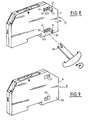
- the torque applied to the bimetallic strip to deform it is exerted manually by means, for example, of a tool ending in a fork, visible at 48 in FIG. 8.
- a tool ending in a fork visible at 48 in FIG. 8.
- one of the two large side walls 50 of the housing 11 comprises a first rectangular window 52 facing which the end 32a of the bimetallic strip appears so as to allow the introduction of the tool 48.
- a second rectangular window 54 facing which appears the free end 32b of the bimetallic strip, so as to allow the operator to view the bimetallic strip at during adjustment.
- each of the two rectangular windows 52, 54 (FIG. 8) is bordered by a folding flap 57 which is made in one piece with the side wall 50 of the housing and which is hinged flexibly on the wall 50.
- each flap 57 is in the raised position, as illustrated in FIG. 8, so as to allow access to the windows 52, 54.
- each flap 57 is folded over its window and is locked by snap-fastening by means of an internal spout 59 molded with the flap 57 and snap-on on an internal flange 61 provided on the corresponding window.
- each shutter 57 closes off its associated window by being embedded in the thickness of the housing, so as to reconstitute without additional thickness the side wall 50 of the housing, as shown in FIG. 9.
- the absence of additional thickness on a side wall of the housing is particularly advantageous when it is desired to attach this housing with another identical housing.
- each flap 57 in the latched position is embedded in the thickness of the housing prohibits any possibility of unlocking the flap, the latter thus constituting a tamper-evident closure means.
- passage opening 34a ( Figure 7) formed in the side wall 34 of the housing can also be provided with a folding flap of the type described above, without departing from the scope of the invention.
Landscapes
- Engineering & Computer Science (AREA)
- Manufacturing & Machinery (AREA)
- Breakers (AREA)
- Thermally Actuated Switches (AREA)
- Rotary Switch, Piano Key Switch, And Lever Switch (AREA)
- Switch Cases, Indication, And Locking (AREA)
Priority Applications (1)
| Application Number | Priority Date | Filing Date | Title |
|---|---|---|---|
| AT87401124T ATE65002T1 (de) | 1986-05-28 | 1987-05-20 | Verfahren und einrichtung zum regeln des thermischen stromes eines thermischen bimetallausloesers fuer schutzschalter. |
Applications Claiming Priority (2)
| Application Number | Priority Date | Filing Date | Title |
|---|---|---|---|
| FR8607623 | 1986-05-28 | ||
| FR8607623A FR2599552B1 (fr) | 1986-05-28 | 1986-05-28 | Procede et dispositif de reglage du courant thermique d'un declencheur thermique a bilame pour interrupteur de protection |
Publications (2)
| Publication Number | Publication Date |
|---|---|
| EP0248702A1 true EP0248702A1 (de) | 1987-12-09 |
| EP0248702B1 EP0248702B1 (de) | 1991-07-03 |
Family
ID=9335729
Family Applications (1)
| Application Number | Title | Priority Date | Filing Date |
|---|---|---|---|
| EP87401124A Expired - Lifetime EP0248702B1 (de) | 1986-05-28 | 1987-05-20 | Verfahren und Einrichtung zum Regeln des thermischen Stromes eines thermischen Bimetallauslösers für Schutzschalter |
Country Status (5)
| Country | Link |
|---|---|
| EP (1) | EP0248702B1 (de) |
| KR (1) | KR900003801B1 (de) |
| AT (1) | ATE65002T1 (de) |
| DE (1) | DE3771129D1 (de) |
| FR (1) | FR2599552B1 (de) |
Cited By (1)
| Publication number | Priority date | Publication date | Assignee | Title |
|---|---|---|---|---|
| EP0334801A1 (de) * | 1988-03-22 | 1989-09-27 | Siemens Aktiengesellschaft | Verfahren und Vorrichtung zum Justieren eines Bimetallauslösers |
Citations (4)
| Publication number | Priority date | Publication date | Assignee | Title |
|---|---|---|---|---|
| DE873584C (de) * | 1946-09-24 | 1953-04-16 | Licentia Gmbh | Verfahren zur Einstellung von thermischen Ausloesern |
| US3596352A (en) * | 1968-04-16 | 1971-08-03 | Smith Corp A O | Method of calibrating bimetallic elements in a thermal overload switch |
| FR2124513A1 (de) * | 1971-02-06 | 1972-09-22 | Siemens Ag | |
| DE2646840A1 (de) * | 1976-10-16 | 1978-04-20 | Bbc Brown Boveri & Cie | Elektrischer schutzschalter |
-
1986
- 1986-05-28 FR FR8607623A patent/FR2599552B1/fr not_active Expired - Lifetime
-
1987
- 1987-05-20 EP EP87401124A patent/EP0248702B1/de not_active Expired - Lifetime
- 1987-05-20 DE DE8787401124T patent/DE3771129D1/de not_active Expired - Lifetime
- 1987-05-20 AT AT87401124T patent/ATE65002T1/de not_active IP Right Cessation
- 1987-05-26 KR KR1019870005216A patent/KR900003801B1/ko not_active Expired
Patent Citations (4)
| Publication number | Priority date | Publication date | Assignee | Title |
|---|---|---|---|---|
| DE873584C (de) * | 1946-09-24 | 1953-04-16 | Licentia Gmbh | Verfahren zur Einstellung von thermischen Ausloesern |
| US3596352A (en) * | 1968-04-16 | 1971-08-03 | Smith Corp A O | Method of calibrating bimetallic elements in a thermal overload switch |
| FR2124513A1 (de) * | 1971-02-06 | 1972-09-22 | Siemens Ag | |
| DE2646840A1 (de) * | 1976-10-16 | 1978-04-20 | Bbc Brown Boveri & Cie | Elektrischer schutzschalter |
Cited By (2)
| Publication number | Priority date | Publication date | Assignee | Title |
|---|---|---|---|---|
| EP0334801A1 (de) * | 1988-03-22 | 1989-09-27 | Siemens Aktiengesellschaft | Verfahren und Vorrichtung zum Justieren eines Bimetallauslösers |
| US4947122A (en) * | 1988-03-22 | 1990-08-07 | Siemens Aktiengesellschaft | Method and apparatus for adjusting a bimetal trip element |
Also Published As
| Publication number | Publication date |
|---|---|
| FR2599552A1 (fr) | 1987-12-04 |
| EP0248702B1 (de) | 1991-07-03 |
| DE3771129D1 (de) | 1991-08-08 |
| KR870011649A (ko) | 1987-12-24 |
| ATE65002T1 (de) | 1991-07-15 |
| FR2599552B1 (fr) | 1993-04-16 |
| KR900003801B1 (ko) | 1990-05-31 |
Similar Documents
| Publication | Publication Date | Title |
|---|---|---|
| EP0620579B1 (de) | Einstellvorrichtung des Auslöseansprechwerts eines mehrpoligen Schutzschalters | |
| EP1975971B1 (de) | Bedienungsvorrichtung eines elektrischen Sicherungsgeräts und elektrisches Sicherungsgerät, das sie umfasst | |
| EP1542253B1 (de) | Anzeigeeinrichtung einer Auslöseeinrichtung eines elektrischen Schutzgeräts | |
| EP2717284B1 (de) | Bedienungsvorrichtung eines elektrischen Schutzschaltgeräts, und diese umfassendes elektrisches Schutzschaltgerät | |
| FR2686453A1 (fr) | Interrupteur differentiel. | |
| EP0248702B1 (de) | Verfahren und Einrichtung zum Regeln des thermischen Stromes eines thermischen Bimetallauslösers für Schutzschalter | |
| FR2683399A1 (fr) | Ensemble de connexion du type a bouclage de circuit. | |
| EP0258124A1 (de) | Riegelvorrichtung des thermischen Stroms einer thermischen Auslösevorrichtung mit Bimetall und Schutzschalter mit einer solchen Vorrichtung | |
| EP1703533B1 (de) | Anzeigesystem für magnetische Fehler | |
| EP0209433B1 (de) | Kontaktträger, insbesondere für Schutzschalter | |
| EP3249673B1 (de) | Vorrichtung zur signalisierung einer elektrischen störung in einem elektrischen schutzgerät, und elektrisches schutzgerät, das eine solche vorrichtung umfasst | |
| EP0461027B1 (de) | Differential Auslösevorrichtung | |
| FR2585180A1 (fr) | Dispositif de reglage du courant thermique d'un organe de declenchement thermique a bilame et appareil interrupteur de protection comportant un tel dispositif | |
| EP0054499B1 (de) | Schalter mit Trennung des Nulleiters | |
| EP2642502B1 (de) | Auslöseblock für elektrisches Sicherungsgerät, und mit einem solchen Block ausgestattetes elektrisches Sicherungsgerät | |
| EP0327460A1 (de) | Elektrischer Schalter mit automatischer Ausschaltung, insbesondere Differentialschutz | |
| EP1953779B1 (de) | Sicherunglasttrennschalter mit Schnellverschlusssicherung | |
| FR2486304A1 (fr) | Interrupteur magneto-thermique differentiel | |
| FR2723469A1 (fr) | Dispositif de declenchement magnetique pour disjoncteur et disjoncteur muni d'un tel dispositif | |
| FR2530072A1 (fr) | Dispositif commutateur, notamment disjoncteur du type a enclenchement par enfoncement puis relachement d'un bouton-poussoir et a declenchement par la deformation d'une lame bimetallique | |
| EP0218497A1 (de) | Schutzschalter mit federnder Lasche | |
| FR2462017A1 (fr) | Coupe-circuit comportant un moyen de signalisation de precoupure, de fusion de cartouche ou d'absence de cartouche | |
| FR2766292A1 (fr) | Dispositif de commande d'un appareil de protection electrique tel un disjoncteur comprenant un moyen de signalisation du declenchement, et disjoncteur equipe d'un tel dispositif | |
| FR2894382A1 (fr) | Declencheur thermique reglable pour dispositif de coupure | |
| EP0310468A1 (de) | Schutzschalter mit Blende zum Unterbrechen des Lichtbogens |
Legal Events
| Date | Code | Title | Description |
|---|---|---|---|
| PUAI | Public reference made under article 153(3) epc to a published international application that has entered the european phase |
Free format text: ORIGINAL CODE: 0009012 |
|
| 17P | Request for examination filed |
Effective date: 19870526 |
|
| AK | Designated contracting states |
Kind code of ref document: A1 Designated state(s): AT BE CH DE GB IT LI SE |
|
| 17Q | First examination report despatched |
Effective date: 19900402 |
|
| RAP1 | Party data changed (applicant data changed or rights of an application transferred) |
Owner name: TELEMECANIQUE |
|
| GRAA | (expected) grant |
Free format text: ORIGINAL CODE: 0009210 |
|
| AK | Designated contracting states |
Kind code of ref document: B1 Designated state(s): AT BE CH DE GB IT LI SE |
|
| REF | Corresponds to: |
Ref document number: 65002 Country of ref document: AT Date of ref document: 19910715 Kind code of ref document: T |
|
| ITF | It: translation for a ep patent filed | ||
| GBT | Gb: translation of ep patent filed (gb section 77(6)(a)/1977) | ||
| REF | Corresponds to: |
Ref document number: 3771129 Country of ref document: DE Date of ref document: 19910808 |
|
| PLBE | No opposition filed within time limit |
Free format text: ORIGINAL CODE: 0009261 |
|
| STAA | Information on the status of an ep patent application or granted ep patent |
Free format text: STATUS: NO OPPOSITION FILED WITHIN TIME LIMIT |
|
| 26N | No opposition filed | ||
| EAL | Se: european patent in force in sweden |
Ref document number: 87401124.0 |
|
| PGFP | Annual fee paid to national office [announced via postgrant information from national office to epo] |
Ref country code: AT Payment date: 19950411 Year of fee payment: 9 |
|
| PGFP | Annual fee paid to national office [announced via postgrant information from national office to epo] |
Ref country code: GB Payment date: 19950512 Year of fee payment: 9 |
|
| PGFP | Annual fee paid to national office [announced via postgrant information from national office to epo] |
Ref country code: CH Payment date: 19950517 Year of fee payment: 9 |
|
| PGFP | Annual fee paid to national office [announced via postgrant information from national office to epo] |
Ref country code: SE Payment date: 19950524 Year of fee payment: 9 Ref country code: DE Payment date: 19950524 Year of fee payment: 9 |
|
| PGFP | Annual fee paid to national office [announced via postgrant information from national office to epo] |
Ref country code: BE Payment date: 19950613 Year of fee payment: 9 |
|
| PG25 | Lapsed in a contracting state [announced via postgrant information from national office to epo] |
Ref country code: GB Effective date: 19960520 Ref country code: AT Effective date: 19960520 |
|
| PG25 | Lapsed in a contracting state [announced via postgrant information from national office to epo] |
Ref country code: SE Effective date: 19960521 |
|
| PG25 | Lapsed in a contracting state [announced via postgrant information from national office to epo] |
Ref country code: LI Effective date: 19960531 Ref country code: CH Effective date: 19960531 Ref country code: BE Effective date: 19960531 |
|
| BERE | Be: lapsed |
Owner name: TELEMECANIQUE Effective date: 19960531 |
|
| GBPC | Gb: european patent ceased through non-payment of renewal fee |
Effective date: 19960520 |
|
| REG | Reference to a national code |
Ref country code: CH Ref legal event code: PL |
|
| PG25 | Lapsed in a contracting state [announced via postgrant information from national office to epo] |
Ref country code: DE Effective date: 19970201 |
|
| EUG | Se: european patent has lapsed |
Ref document number: 87401124.0 |
|
| PG25 | Lapsed in a contracting state [announced via postgrant information from national office to epo] |
Ref country code: IT Free format text: LAPSE BECAUSE OF NON-PAYMENT OF DUE FEES;WARNING: LAPSES OF ITALIAN PATENTS WITH EFFECTIVE DATE BEFORE 2007 MAY HAVE OCCURRED AT ANY TIME BEFORE 2007. THE CORRECT EFFECTIVE DATE MAY BE DIFFERENT FROM THE ONE RECORDED. Effective date: 20050520 |