EP0249059A1 - Actionnement par air comprimé pour des dispositifs de poinçonnage, coupe et estampage - Google Patents
Actionnement par air comprimé pour des dispositifs de poinçonnage, coupe et estampage Download PDFInfo
- Publication number
- EP0249059A1 EP0249059A1 EP87107223A EP87107223A EP0249059A1 EP 0249059 A1 EP0249059 A1 EP 0249059A1 EP 87107223 A EP87107223 A EP 87107223A EP 87107223 A EP87107223 A EP 87107223A EP 0249059 A1 EP0249059 A1 EP 0249059A1
- Authority
- EP
- European Patent Office
- Prior art keywords
- compressed air
- piston
- cylinder
- piston rod
- drive according
- Prior art date
- Legal status (The legal status is an assumption and is not a legal conclusion. Google has not performed a legal analysis and makes no representation as to the accuracy of the status listed.)
- Granted
Links
- 238000005520 cutting process Methods 0.000 title claims abstract description 34
- 238000004080 punching Methods 0.000 title claims abstract description 8
- 238000004806 packaging method and process Methods 0.000 claims description 13
- 238000004049 embossing Methods 0.000 claims description 6
- 238000010276 construction Methods 0.000 description 5
- 238000004519 manufacturing process Methods 0.000 description 3
- 238000007789 sealing Methods 0.000 description 3
- 230000006378 damage Effects 0.000 description 2
- 239000011888 foil Substances 0.000 description 2
- 238000000034 method Methods 0.000 description 2
- 230000000903 blocking effect Effects 0.000 description 1
- 238000006073 displacement reaction Methods 0.000 description 1
- 239000010720 hydraulic oil Substances 0.000 description 1
Images


Classifications
-
- B—PERFORMING OPERATIONS; TRANSPORTING
- B26—HAND CUTTING TOOLS; CUTTING; SEVERING
- B26D—CUTTING; DETAILS COMMON TO MACHINES FOR PERFORATING, PUNCHING, CUTTING-OUT, STAMPING-OUT OR SEVERING
- B26D1/00—Cutting through work characterised by the nature or movement of the cutting member or particular materials not otherwise provided for; Apparatus or machines therefor; Cutting members therefor
- B26D1/01—Cutting through work characterised by the nature or movement of the cutting member or particular materials not otherwise provided for; Apparatus or machines therefor; Cutting members therefor involving a cutting member which does not travel with the work
- B26D1/04—Cutting through work characterised by the nature or movement of the cutting member or particular materials not otherwise provided for; Apparatus or machines therefor; Cutting members therefor involving a cutting member which does not travel with the work having a linearly-movable cutting member
- B26D1/06—Cutting through work characterised by the nature or movement of the cutting member or particular materials not otherwise provided for; Apparatus or machines therefor; Cutting members therefor involving a cutting member which does not travel with the work having a linearly-movable cutting member wherein the cutting member reciprocates
- B26D1/08—Cutting through work characterised by the nature or movement of the cutting member or particular materials not otherwise provided for; Apparatus or machines therefor; Cutting members therefor involving a cutting member which does not travel with the work having a linearly-movable cutting member wherein the cutting member reciprocates of the guillotine type
- B26D1/09—Cutting through work characterised by the nature or movement of the cutting member or particular materials not otherwise provided for; Apparatus or machines therefor; Cutting members therefor involving a cutting member which does not travel with the work having a linearly-movable cutting member wherein the cutting member reciprocates of the guillotine type with a plurality of cutting members
-
- B—PERFORMING OPERATIONS; TRANSPORTING
- B26—HAND CUTTING TOOLS; CUTTING; SEVERING
- B26D—CUTTING; DETAILS COMMON TO MACHINES FOR PERFORATING, PUNCHING, CUTTING-OUT, STAMPING-OUT OR SEVERING
- B26D5/00—Arrangements for operating and controlling machines or devices for cutting, cutting-out, stamping-out, punching, perforating, or severing by means other than cutting
- B26D5/08—Means for actuating the cutting member to effect the cut
- B26D5/12—Fluid-pressure means
-
- Y—GENERAL TAGGING OF NEW TECHNOLOGICAL DEVELOPMENTS; GENERAL TAGGING OF CROSS-SECTIONAL TECHNOLOGIES SPANNING OVER SEVERAL SECTIONS OF THE IPC; TECHNICAL SUBJECTS COVERED BY FORMER USPC CROSS-REFERENCE ART COLLECTIONS [XRACs] AND DIGESTS
- Y10—TECHNICAL SUBJECTS COVERED BY FORMER USPC
- Y10T—TECHNICAL SUBJECTS COVERED BY FORMER US CLASSIFICATION
- Y10T83/00—Cutting
- Y10T83/869—Means to drive or to guide tool
- Y10T83/8735—With means providing for plural steps in tool stroke
-
- Y—GENERAL TAGGING OF NEW TECHNOLOGICAL DEVELOPMENTS; GENERAL TAGGING OF CROSS-SECTIONAL TECHNOLOGIES SPANNING OVER SEVERAL SECTIONS OF THE IPC; TECHNICAL SUBJECTS COVERED BY FORMER USPC CROSS-REFERENCE ART COLLECTIONS [XRACs] AND DIGESTS
- Y10—TECHNICAL SUBJECTS COVERED BY FORMER USPC
- Y10T—TECHNICAL SUBJECTS COVERED BY FORMER US CLASSIFICATION
- Y10T83/00—Cutting
- Y10T83/869—Means to drive or to guide tool
- Y10T83/8821—With simple rectilinear reciprocating motion only
- Y10T83/8827—Means to vary force on, or speed of, tool during stroke
-
- Y—GENERAL TAGGING OF NEW TECHNOLOGICAL DEVELOPMENTS; GENERAL TAGGING OF CROSS-SECTIONAL TECHNOLOGIES SPANNING OVER SEVERAL SECTIONS OF THE IPC; TECHNICAL SUBJECTS COVERED BY FORMER USPC CROSS-REFERENCE ART COLLECTIONS [XRACs] AND DIGESTS
- Y10—TECHNICAL SUBJECTS COVERED BY FORMER USPC
- Y10T—TECHNICAL SUBJECTS COVERED BY FORMER US CLASSIFICATION
- Y10T83/00—Cutting
- Y10T83/869—Means to drive or to guide tool
- Y10T83/8821—With simple rectilinear reciprocating motion only
- Y10T83/8858—Fluid pressure actuated
- Y10T83/8864—Plural cylinders
Definitions
- the invention relates to a compressed air drive for punching, cutting and embossing devices, with two mutually movable tool parts, one of which is advantageously firmly connected to the machine frame at least in the working position, in particular for cutting devices for packaging machines with a large opening width.
- the invention is based on the object of designing a drive for punching, cutting and embossing devices of the type mentioned at the outset such that they can be produced with an essentially arbitrarily large opening gap so that they can be operated with a low pressure when the tool parts are moved together, so that additional safety devices can be dispensed with, that the drive is simple in construction and economical in production with a relatively small construction volume, and that the required clamping force and thus cutting, embossing and punching force can be generated at the same time.
- the compressed air drive for punching, cutting and embossing devices thus consists of at least one compressed air cylinder which is connected to the movable tool part.
- the piston rod of the compressed air cylinder is connected to a further piston rod of a second compressed air clamping element, which can be fixed on the machine frame. If a flat top film is used here, it can be permanently connected to the machine frame. In the other case, this must also be designed to be raised and lowered.
- the compressed air cylinder which is connected to the movable tool part, can be designed with the required length, so that this tool part occupies the required opening gap for the further transport of the packaging.
- This compressed air cylinder can be subjected to a relatively low pressure, so that the force exerted by it is less than 15 kp, ie below a force at which no injuries are to be feared and additional safety devices are therefore unnecessary.
- the piston rod is mechanically blocked, whereby this blocking device can be integrated in the interior of the air pressure cylinder or by means of a bolt which is inserted into a recess in the piston rod and thus fixes it relative to the cylinder.
- the lower tool part rests on the knife with a contact pressure of less than 15 kp.
- compressed air is added to the compressed air clamping element, so that the now locked piston rod is acted upon with great force, which can be 9 t and more, and so the knife is pressed against the abutment, so that the film is cut.
- the compressed air tensioning element consists of several piston cylinder units connected in series, whereby the diameter of the compressed air tensioning element can be kept relatively small with a high force generation.
- the path that the compressed air tensioning element has to cover can then only be a few mm, which is quite sufficient, for example, for cutting a film. However, this path can also be enlarged at the expense of the overall height to be sufficient, for example, for embossing and punching devices.
- the compressed air clamping element advantageously consists of a plurality of individual parts which are held in a ring-shaped manner and pressed against one another and which have a central bore through which the piston rod engages. Through this central bore, a tubular extension arranged on the piston also engages, each piston being supported on the preceding and following pistons, so that a high compressive force can be built up with a relatively small diameter in the case of a plurality of pistons arranged one behind the other.
- the compressed air inlets and outlets are obtained in the ring-shaped parts through bores which penetrate them and which lie one above the other after assembly. This makes it possible to supply the large number of piston units one behind the other with two external compressed air connections.
- two drive units are advantageously used, which are arranged on both sides of the cutting device, the two compressed air clamping elements being connected to one another via plates to which the one tool part carrying the knife is fastened.
- a device according to the invention thus allows opening gaps of any size to be produced between the two tool parts, which are only limited by the height of the machine frame.
- the device according to the invention consists of comparatively few individual parts, which is inexpensive to manufacture and therefore very economical Chen construction that works wear-free and still delivers the required large contact pressures.
- the two tool parts are moved together at a relatively low pressure, not only is a safety device saved, but the air consumption as such is also significantly reduced.
- the actual working stroke, which is carried out with a high air pressure, is thus limited to the minimum, so that the device as a whole works very economically.
- a cutting device 2 of a packaging device 1 which has an upper tool part 3, which carries the knife 4, and a lower tool part 5, which serves as a counter bearing for the knife 4.
- Fig.l shows the container 6 in side view and in section, which are formed from a lower film 7, which is deformed like a cup, and an upper film 8.
- the top and bottom films have been welded together in a known manner in a sealing station arranged in front of the cutting station.
- the cutting device 2 By means of the cutting device 2, the containers 6 are separated in the transverse position in the region of the intermediate space 9 formed between them.
- the top film 8 is flat, so that the upper tool part 3 can be fixedly connected to the machine frame 10.
- two guide strips 11 are arranged in each case, which receive guide profiles 12 which have a recess corresponding to the guide strips 11.
- These guide profiles are adjustable along the machine frame 10, so that the cutting device 2 can be adjusted accordingly depending on the respective sizes of the containers 6.
- a toothing l3 is attached, into which a gearwheel l4 rotatably arranged on the machine frame 10 engages.
- the two gear wheels, which each engage in the guide bar 11 on the two sides of the foils 7, 8, are connected to one another via an axis l5, so that tilting is avoided when the cutting device 2 is displaced.
- a handwheel 16 is rotatably fastened on one side on the axis l5, which projects laterally beyond the machine frame 10 on one side.
- the chain guides 17, 18 for an endless chain are arranged, which have clamping elements 19, with which the bottom film 7 is gripped and transported at the edges. With the help of these chains, the containers are transported in cycles and positioned in the corresponding position of the cutting device 2.
- a compressed air tensioning element 2O which consists of several piston cylinder units connected in series and has a piston rod 2l common to all piston cylinder units, is fixedly connected to the guide profile 12.
- Each compressed air clamping element 2O has a base 22 which is screwed to the guide profile 12.
- Two plates 23, which connect the compressed air tensioning elements 20 to one another, are fastened to this socket 22 and are thus fixed in place on the machine frame 10 via the socket 22.
- the plates 23 are arranged parallel to one another and lie on edge, as can best be seen from FIG. 1.
- two plates 24, 25 receiving and supporting the knife 4 of the cutting device are fastened by means of screws 26 which engage in lateral projections 27 of the plates 23.
- the lower tool part 5 consists of a plate which extends over the width of the foils 6, 7 and is fastened on both sides to the cylinder wall 28 of a compressed air cylinder 29.
- the compressed air cylinder has, in a known manner, a piston rod 3O and a piston 3l arranged at the end of the piston rod 30.
- the compressed air cylinder is double-acting, the piston rod 30 emerging from the cylinder through a hermetically sealing seal.
- the piston rod 30 is arranged in the extension of the piston rod 2l of the compressed air clamping element and is fixedly connected to it by means of a screw 32.
- the lower tool part is shown in the left half of the drawing in the raised position, ie in the cutting position, and in the right half of the drawing in the lowered position, ie in the position in which the containers 6 enter the cutting device or can be transported out of this again.
- the knife 4 is somewhat narrower than the width of the bottom film, so that the packaging is still connected at the edges and can therefore be transported further by means of the chains.
- the length of the compressed air cylinder piston 29 can be chosen to be of any size, so that an opening gap of any size can be obtained for the transport of the containers 6.
- the compressed air cylinder pistons 29 are advantageously subjected to a relatively low pressure, which on the one hand reduces the compressed air consumption and on the other hand has the consequence that the closing force of the compressed air cylinder pistons can be kept less than 15 kp. This makes it possible to save on special safety devices, because even if an operator's hand gets between the upper and lower tools during the closing process, no damage can occur here.
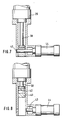
- FIG. 6 which in turn shows the retracted position in the left half of the drawing and the extended position in the right half of the drawing, the piston rod 30 is automatically in its lower end position, ie in the retracted position of the two tool parts, locked. This is done via a ring 33 which engages in a groove 34 of the piston rod 30.
- a sleeve 36 is slidably arranged, which cooperates with a spring 37. If there is no pressure in the cylinder space 38, the spring 37 presses the sleeve 36 upward, so that the ring 33 is held in the groove 34 of the piston 30.
- FIG. 7 and 8 another embodiment of a locking of the piston rod 30 is shown, specifically here an eye 41 with a bore 42 is arranged at the end of the piston rod 30, into which a bolt 43 can be inserted, which is connected by a further compressed air cylinder 44 can be actuated.
- an eye 41 with a bore 42 is arranged at the end of the piston rod 30, into which a bolt 43 can be inserted, which is connected by a further compressed air cylinder 44 can be actuated.
- the piston rod 30 In the raised position of the lower tool part 5, i.e. in the position in which the actual cutting force can be built up, the piston rod 30 is locked against the cylinder wall 28 by inserting the bolt 43, so that the lower tool part 5 is now rigidly connected to the piston rod 30.
- the compressed air clamping element 2O is shown in FIGS. 4 and 5 in an enlarged view.
- the compressed air clamping element consists of a base 22 on which a plurality of ring elements 45 of the same design are placed, in the exemplary embodiment these are seven pieces.
- Each ring element has a central bore 46 and a recess 47 arranged on one side and two through bores 48, 49. From these through bores 48, 49 branch off channels 50, 51, which are used for supplying compressed air to one side of the annular part 45.
- the central bore 46 is so large that it serves on the one hand for receiving the piston rod 2l and on the other hand for receiving an annular bushing 52 of a piston 53.
- the inside of the piston in the area of the bushing 52 has an O-ring seal 54 which seals the piston against the piston rod 2l.
- two further O-ring seals 55, 56 are arranged on the surfaces parallel to the piston rod, which serve to seal the annular part against the piston or the bushing of the piston. All pistons 53 are supported against one another via their bushings 52, so that the force of the individual piston-cylinder units is added, so that, with a relatively small diameter, very high forces can be built up by selecting the number of piston-cylinder units.
- each piston-cylinder unit is advantageously chosen so that it delivers a pressure force of approximately 600 kp at a pressure of 6 bar.
- each compressed air clamping element thus delivers approximately 4.2 t, so that a total contact pressure of the knife 4 on the lower tool part 5 of slightly over 8 t is obtained.
- the path that the compressed air clamping element 2O provides only has to be very small.
- a path of 3 mm has proven to be quite sufficient, so that with the compressed air tensioning device according to the invention with a comparatively small diameter and comparatively low height very high compressive forces can be generated, which are required for cutting films.
- the compressed air clamping element is also characterized by great simplicity in its construction, since it consists essentially of the same annular elements and pistons, which are stacked on one another in any number depending on the required compressive force and then screwed onto the nuts 58 by means of clamping screws 57 will.
- Each ring-shaped element 45 is thus of identical design, these ring-shaped elements being pressed together between the block 22 and an end piece 6l, which can basically be designed in the same way as the ring-shaped elements 45, but without the bore 49.
- the piston rod 2l of the compressed air clamping element 2O is passed through the compressed air clamping element and provided at its end with thread 63, onto which two screws 64 are screwed to fix the piston rod 2l on the compressed air clamping element. This enables simple assembly and disassembly of the clamping element, which can be attached or detached completely assembled to the cutting device 2.
Landscapes
- Life Sciences & Earth Sciences (AREA)
- Forests & Forestry (AREA)
- Engineering & Computer Science (AREA)
- Mechanical Engineering (AREA)
- Perforating, Stamping-Out Or Severing By Means Other Than Cutting (AREA)
- Control Of Cutting Processes (AREA)
Priority Applications (1)
| Application Number | Priority Date | Filing Date | Title |
|---|---|---|---|
| AT87107223T ATE50722T1 (de) | 1986-06-12 | 1987-05-19 | Druckluftantrieb fuer stanz-, schneid- und praegeeinrichtungen. |
Applications Claiming Priority (2)
| Application Number | Priority Date | Filing Date | Title |
|---|---|---|---|
| DE3619811 | 1986-06-12 | ||
| DE19863619811 DE3619811A1 (de) | 1986-06-12 | 1986-06-12 | Druckluftantrieb fuer stanz-, schneid- und praegeeinrichtungen |
Publications (2)
| Publication Number | Publication Date |
|---|---|
| EP0249059A1 true EP0249059A1 (fr) | 1987-12-16 |
| EP0249059B1 EP0249059B1 (fr) | 1990-03-07 |
Family
ID=6302884
Family Applications (1)
| Application Number | Title | Priority Date | Filing Date |
|---|---|---|---|
| EP87107223A Expired - Lifetime EP0249059B1 (fr) | 1986-06-12 | 1987-05-19 | Actionnement par air comprimé pour des dispositifs de poinçonnage, coupe et estampage |
Country Status (5)
| Country | Link |
|---|---|
| US (1) | US4798115A (fr) |
| EP (1) | EP0249059B1 (fr) |
| JP (1) | JPS62292395A (fr) |
| AT (1) | ATE50722T1 (fr) |
| DE (2) | DE3619811A1 (fr) |
Cited By (2)
| Publication number | Priority date | Publication date | Assignee | Title |
|---|---|---|---|---|
| US4798115A (en) * | 1986-06-12 | 1989-01-17 | Kraemer & Grebe Gmbh & Co. Kg Maschinenfabrik | Pneumatic drive for punching, cutting and stamping devices |
| EP3428079A1 (fr) | 2017-07-14 | 2019-01-16 | MULTIVAC Sepp Haggenmüller SE & Co. KG | Emboutisseuse d'emballage comprenant un support d'emballage souple |
Families Citing this family (7)
| Publication number | Priority date | Publication date | Assignee | Title |
|---|---|---|---|---|
| DE4216207C1 (fr) * | 1992-05-15 | 1993-08-19 | Multivac Sepp Haggenmueller Kg, 8941 Wolfertschwenden, De | |
| US5909921A (en) * | 1997-04-11 | 1999-06-08 | Nesbeth; Roleto E. | Lift device and system for a pick-up truck cargo cover |
| US6526865B2 (en) | 2001-04-25 | 2003-03-04 | Smc Corporation Of America | Weld cylinder |
| DE102012000127A1 (de) | 2012-01-06 | 2013-07-11 | Gea Cfs Germany Gmbh | Verpackungsmaschine mit einer Schneidstation |
| DE102012224532A1 (de) * | 2012-12-28 | 2014-07-03 | Sms Siemag Ag | Mitfahrende hydraulische Schere ohne Ständer |
| CN110076829B (zh) * | 2019-05-24 | 2021-04-13 | 深圳市中怡医卫新材料有限公司 | 一种切割棉签边角料装置 |
| CN112440328B (zh) * | 2020-09-14 | 2022-06-10 | 佛山华兴塑料制品有限公司 | 一种活塞l型自动成型机 |
Citations (4)
| Publication number | Priority date | Publication date | Assignee | Title |
|---|---|---|---|---|
| GB1353708A (en) * | 1972-02-04 | 1974-05-22 | Multivac Haggenmueller Kg | Cutter for cutting wrappers of foil |
| GB2055667A (en) * | 1979-08-14 | 1981-03-11 | Thompson J E | Guillotines |
| DE3248574A1 (de) * | 1982-12-30 | 1984-07-12 | VTM Maschinen- und Apparatebau GmbH & Co KG, 4350 Recklinghausen | Querschneider zum durchtrennen von folienbahnen z.b. in verpackungsmaschinen |
| US4583436A (en) * | 1983-12-23 | 1986-04-22 | Kabushiki Kaisha Asano Kenkyusho | Apparatus for trimming articles moldingly formed on plastic sheet |
Family Cites Families (12)
| Publication number | Priority date | Publication date | Assignee | Title |
|---|---|---|---|---|
| US860009A (en) * | 1907-01-05 | 1907-07-16 | Jacob Becker | Machine for shearing and pressing. |
| US897048A (en) * | 1908-01-02 | 1908-08-25 | Wiland Astfalck | Drawback mechanism for presses. |
| US2740472A (en) * | 1952-02-01 | 1956-04-03 | George R Eckstein | Shearing machine |
| US2825405A (en) * | 1954-02-19 | 1958-03-04 | Schloemann Ag | Hydraulically operated ingot-shearing machines |
| US3036798A (en) * | 1958-03-14 | 1962-05-29 | Martin James | Cutter unit primarily for use in ejection seats for aircraft |
| US3371569A (en) * | 1965-06-28 | 1968-03-05 | Pacific Press & Shear Corp | Shear machine or the like |
| US3847528A (en) * | 1972-11-29 | 1974-11-12 | Improved Machinery Inc | Clamping force applying means for molding machines |
| US3908496A (en) * | 1973-01-18 | 1975-09-30 | Advanced Machine Design Co | Hydraulic shearing machine |
| US4024794A (en) * | 1973-02-02 | 1977-05-24 | Amp Incorporated | Pneumatically operated cable-slitting tool |
| DE2419390C2 (de) * | 1974-04-23 | 1983-09-29 | SMG Süddeutsche Maschinenbau-Gesellschaft mbH, 6833 Waghäusel | Werkzeugbruchsicherung |
| SE396639B (sv) * | 1976-03-03 | 1977-09-26 | Westin & Backlund Ab | Regulator innefattande ett antal kammare till vilka tryckmedium tillfores eller avledes for att via tryckoverforande element bibringa en i regulatorn forskjutbart lagrad utgaende axel rorelse |
| DE3619811A1 (de) * | 1986-06-12 | 1987-12-17 | Kraemer & Grebe Kg | Druckluftantrieb fuer stanz-, schneid- und praegeeinrichtungen |
-
1986
- 1986-06-12 DE DE19863619811 patent/DE3619811A1/de not_active Ceased
-
1987
- 1987-05-19 EP EP87107223A patent/EP0249059B1/fr not_active Expired - Lifetime
- 1987-05-19 AT AT87107223T patent/ATE50722T1/de not_active IP Right Cessation
- 1987-05-19 DE DE8787107223T patent/DE3761802D1/de not_active Expired - Lifetime
- 1987-06-05 US US07/058,469 patent/US4798115A/en not_active Expired - Fee Related
- 1987-06-12 JP JP62145433A patent/JPS62292395A/ja active Pending
Patent Citations (4)
| Publication number | Priority date | Publication date | Assignee | Title |
|---|---|---|---|---|
| GB1353708A (en) * | 1972-02-04 | 1974-05-22 | Multivac Haggenmueller Kg | Cutter for cutting wrappers of foil |
| GB2055667A (en) * | 1979-08-14 | 1981-03-11 | Thompson J E | Guillotines |
| DE3248574A1 (de) * | 1982-12-30 | 1984-07-12 | VTM Maschinen- und Apparatebau GmbH & Co KG, 4350 Recklinghausen | Querschneider zum durchtrennen von folienbahnen z.b. in verpackungsmaschinen |
| US4583436A (en) * | 1983-12-23 | 1986-04-22 | Kabushiki Kaisha Asano Kenkyusho | Apparatus for trimming articles moldingly formed on plastic sheet |
Cited By (4)
| Publication number | Priority date | Publication date | Assignee | Title |
|---|---|---|---|---|
| US4798115A (en) * | 1986-06-12 | 1989-01-17 | Kraemer & Grebe Gmbh & Co. Kg Maschinenfabrik | Pneumatic drive for punching, cutting and stamping devices |
| EP3428079A1 (fr) | 2017-07-14 | 2019-01-16 | MULTIVAC Sepp Haggenmüller SE & Co. KG | Emboutisseuse d'emballage comprenant un support d'emballage souple |
| CN109250224A (zh) * | 2017-07-14 | 2019-01-22 | 莫迪维克西普哈根牧勒股份及两合公司 | 具有灵活的包装支撑件的热成形包装机 |
| US11505342B2 (en) | 2017-07-14 | 2022-11-22 | Multivac Sepp Haggenmueller Se & Co. Kg | Thermoform packaging machine with flexible package support |
Also Published As
| Publication number | Publication date |
|---|---|
| US4798115A (en) | 1989-01-17 |
| JPS62292395A (ja) | 1987-12-19 |
| DE3619811A1 (de) | 1987-12-17 |
| DE3761802D1 (de) | 1990-04-12 |
| ATE50722T1 (de) | 1990-03-15 |
| EP0249059B1 (fr) | 1990-03-07 |
Similar Documents
| Publication | Publication Date | Title |
|---|---|---|
| DE69321728T2 (de) | Zweistufiger matritzensatz | |
| DE3931320C1 (fr) | ||
| EP2103423B1 (fr) | Presse à poudre destinée à la fabrication d'une pièce pressée en poudre de métal | |
| DE2824488C2 (de) | Vorrichtung zum Ausstanzen | |
| DE2537865C2 (fr) | ||
| EP3712079B1 (fr) | Poste de travail pourvu de mécanisme de levage pour une machine d'emballage | |
| EP0569937A1 (fr) | Station de travail d'une machine d'emballage comprenant une partie inférieure mobile | |
| EP1202825B1 (fr) | Procede et dispositif pour la formation d'un coin limite sur trois cotes a partir d'un materiau en forme de plaque et a surface plane | |
| EP0249059B1 (fr) | Actionnement par air comprimé pour des dispositifs de poinçonnage, coupe et estampage | |
| DE2242204C3 (de) | Druckmittelbeaufschlagter Servomotor | |
| DE2601858B2 (de) | Stanzmaschine | |
| DE2620545A1 (de) | Tragbare presse | |
| DE2841684A1 (de) | Presse, insbesondere steinpresse | |
| AT390237B (de) | Verpackungsmaschine | |
| DE2542909A1 (de) | Schrottschere, insbesondere zur verarbeitung von flachmaterial | |
| EP1344628B1 (fr) | Appareil pour l'emboutissage de récipients en thermoplastique | |
| DE1752244B2 (de) | Hydraulische Schrottschere mit einer den Schrott seitlich verdichtenden Sei tendruckpresse | |
| DE102006045477A1 (de) | Arbeitsstation für eine Tiefziehmaschine | |
| DE2654000A1 (de) | Maschine zum ausbrechen von nutzen | |
| EP0659501B1 (fr) | Machine à forger | |
| DE2437105A1 (de) | Verstellbare werkzeughalterung an eckverbindungsmaschinen | |
| DE1947796A1 (de) | Stanzmaschine | |
| DE102007037108B4 (de) | Antriebsanordnung für eine Lebensmittelteilvorrichtung | |
| DE4129029A1 (de) | Flachbett-stanzmaschine zum stanzen von flachen gegenstaenden, insbesondere boegen aus papier, pappe oder dergleichen | |
| DE3436998C2 (de) | Druckmittelbetätigte Schere |
Legal Events
| Date | Code | Title | Description |
|---|---|---|---|
| PUAI | Public reference made under article 153(3) epc to a published international application that has entered the european phase |
Free format text: ORIGINAL CODE: 0009012 |
|
| AK | Designated contracting states |
Kind code of ref document: A1 Designated state(s): AT CH DE FR IT LI |
|
| 17P | Request for examination filed |
Effective date: 19880312 |
|
| 17Q | First examination report despatched |
Effective date: 19890720 |
|
| GRAA | (expected) grant |
Free format text: ORIGINAL CODE: 0009210 |
|
| AK | Designated contracting states |
Kind code of ref document: B1 Designated state(s): AT CH DE FR IT LI |
|
| ITF | It: translation for a ep patent filed | ||
| REF | Corresponds to: |
Ref document number: 50722 Country of ref document: AT Date of ref document: 19900315 Kind code of ref document: T |
|
| REF | Corresponds to: |
Ref document number: 3761802 Country of ref document: DE Date of ref document: 19900412 |
|
| ET | Fr: translation filed | ||
| PLBE | No opposition filed within time limit |
Free format text: ORIGINAL CODE: 0009261 |
|
| STAA | Information on the status of an ep patent application or granted ep patent |
Free format text: STATUS: NO OPPOSITION FILED WITHIN TIME LIMIT |
|
| 26N | No opposition filed | ||
| ITTA | It: last paid annual fee | ||
| PGFP | Annual fee paid to national office [announced via postgrant information from national office to epo] |
Ref country code: CH Payment date: 19930405 Year of fee payment: 7 |
|
| PGFP | Annual fee paid to national office [announced via postgrant information from national office to epo] |
Ref country code: FR Payment date: 19930419 Year of fee payment: 7 |
|
| PGFP | Annual fee paid to national office [announced via postgrant information from national office to epo] |
Ref country code: AT Payment date: 19930524 Year of fee payment: 7 |
|
| PGFP | Annual fee paid to national office [announced via postgrant information from national office to epo] |
Ref country code: DE Payment date: 19930710 Year of fee payment: 7 |
|
| PG25 | Lapsed in a contracting state [announced via postgrant information from national office to epo] |
Ref country code: AT Effective date: 19940519 |
|
| PG25 | Lapsed in a contracting state [announced via postgrant information from national office to epo] |
Ref country code: LI Effective date: 19940531 Ref country code: CH Effective date: 19940531 |
|
| PG25 | Lapsed in a contracting state [announced via postgrant information from national office to epo] |
Ref country code: FR Effective date: 19950131 |
|
| REG | Reference to a national code |
Ref country code: CH Ref legal event code: PL |
|
| PG25 | Lapsed in a contracting state [announced via postgrant information from national office to epo] |
Ref country code: DE Effective date: 19950201 |
|
| REG | Reference to a national code |
Ref country code: FR Ref legal event code: ST |
|
| PG25 | Lapsed in a contracting state [announced via postgrant information from national office to epo] |
Ref country code: IT Free format text: LAPSE BECAUSE OF NON-PAYMENT OF DUE FEES;WARNING: LAPSES OF ITALIAN PATENTS WITH EFFECTIVE DATE BEFORE 2007 MAY HAVE OCCURRED AT ANY TIME BEFORE 2007. THE CORRECT EFFECTIVE DATE MAY BE DIFFERENT FROM THE ONE RECORDED. Effective date: 20050519 |