EP0249067A1 - Vorrichtung zum Dämpfen von Druckstössen in Rohrleitungen, insbesondere Sanitärinstallationen - Google Patents
Vorrichtung zum Dämpfen von Druckstössen in Rohrleitungen, insbesondere Sanitärinstallationen Download PDFInfo
- Publication number
- EP0249067A1 EP0249067A1 EP87107342A EP87107342A EP0249067A1 EP 0249067 A1 EP0249067 A1 EP 0249067A1 EP 87107342 A EP87107342 A EP 87107342A EP 87107342 A EP87107342 A EP 87107342A EP 0249067 A1 EP0249067 A1 EP 0249067A1
- Authority
- EP
- European Patent Office
- Prior art keywords
- space
- wall
- chamber
- pipe section
- housing
- Prior art date
- Legal status (The legal status is an assumption and is not a legal conclusion. Google has not performed a legal analysis and makes no representation as to the accuracy of the status listed.)
- Granted
Links
- 238000009434 installation Methods 0.000 title claims abstract description 16
- 238000013016 damping Methods 0.000 title claims description 6
- XLYOFNOQVPJJNP-UHFFFAOYSA-N water Substances O XLYOFNOQVPJJNP-UHFFFAOYSA-N 0.000 title description 10
- 229910052782 aluminium Inorganic materials 0.000 claims description 11
- XAGFODPZIPBFFR-UHFFFAOYSA-N aluminium Chemical compound [Al] XAGFODPZIPBFFR-UHFFFAOYSA-N 0.000 claims description 11
- 239000002775 capsule Substances 0.000 claims description 10
- 239000006260 foam Substances 0.000 claims description 9
- 239000013013 elastic material Substances 0.000 claims description 6
- 238000005192 partition Methods 0.000 claims description 4
- 239000007788 liquid Substances 0.000 claims description 3
- 229920001971 elastomer Polymers 0.000 claims description 2
- 239000000806 elastomer Substances 0.000 claims description 2
- 229910052751 metal Inorganic materials 0.000 claims description 2
- 239000002184 metal Substances 0.000 claims description 2
- 125000006850 spacer group Chemical group 0.000 claims 1
- 239000012528 membrane Substances 0.000 description 15
- 230000002093 peripheral effect Effects 0.000 description 5
- 238000005253 cladding Methods 0.000 description 3
- 239000000945 filler Substances 0.000 description 3
- 239000011888 foil Substances 0.000 description 3
- 238000007789 sealing Methods 0.000 description 3
- 229920000459 Nitrile rubber Polymers 0.000 description 2
- 238000010521 absorption reaction Methods 0.000 description 2
- 239000004033 plastic Substances 0.000 description 2
- 239000011148 porous material Substances 0.000 description 2
- 238000003825 pressing Methods 0.000 description 2
- 229920002943 EPDM rubber Polymers 0.000 description 1
- 239000011248 coating agent Substances 0.000 description 1
- 238000000576 coating method Methods 0.000 description 1
- 150000001875 compounds Chemical class 0.000 description 1
- 238000009792 diffusion process Methods 0.000 description 1
- 238000009826 distribution Methods 0.000 description 1
- 238000002474 experimental method Methods 0.000 description 1
- 239000013505 freshwater Substances 0.000 description 1
- 238000011835 investigation Methods 0.000 description 1
- 238000000034 method Methods 0.000 description 1
- 239000011295 pitch Substances 0.000 description 1
- 229920006124 polyolefin elastomer Polymers 0.000 description 1
- 238000005096 rolling process Methods 0.000 description 1
- 230000035939 shock Effects 0.000 description 1
Images


Classifications
-
- F—MECHANICAL ENGINEERING; LIGHTING; HEATING; WEAPONS; BLASTING
- F17—STORING OR DISTRIBUTING GASES OR LIQUIDS
- F17D—PIPE-LINE SYSTEMS; PIPE-LINES
- F17D1/00—Pipe-line systems
- F17D1/20—Arrangements or systems of devices for influencing or altering dynamic characteristics of the systems, e.g. for damping pulsations caused by opening or closing of valves
-
- F—MECHANICAL ENGINEERING; LIGHTING; HEATING; WEAPONS; BLASTING
- F16—ENGINEERING ELEMENTS AND UNITS; GENERAL MEASURES FOR PRODUCING AND MAINTAINING EFFECTIVE FUNCTIONING OF MACHINES OR INSTALLATIONS; THERMAL INSULATION IN GENERAL
- F16L—PIPES; JOINTS OR FITTINGS FOR PIPES; SUPPORTS FOR PIPES, CABLES OR PROTECTIVE TUBING; MEANS FOR THERMAL INSULATION IN GENERAL
- F16L55/00—Devices or appurtenances for use in, or in connection with, pipes or pipe systems
- F16L55/04—Devices damping pulsations or vibrations in fluids
- F16L55/045—Devices damping pulsations or vibrations in fluids specially adapted to prevent or minimise the effects of water hammer
- F16L55/05—Buffers therefor
- F16L55/052—Pneumatic reservoirs
- F16L55/053—Pneumatic reservoirs the gas in the reservoir being separated from the fluid in the pipe
-
- F—MECHANICAL ENGINEERING; LIGHTING; HEATING; WEAPONS; BLASTING
- F16—ENGINEERING ELEMENTS AND UNITS; GENERAL MEASURES FOR PRODUCING AND MAINTAINING EFFECTIVE FUNCTIONING OF MACHINES OR INSTALLATIONS; THERMAL INSULATION IN GENERAL
- F16L—PIPES; JOINTS OR FITTINGS FOR PIPES; SUPPORTS FOR PIPES, CABLES OR PROTECTIVE TUBING; MEANS FOR THERMAL INSULATION IN GENERAL
- F16L55/00—Devices or appurtenances for use in, or in connection with, pipes or pipe systems
- F16L55/04—Devices damping pulsations or vibrations in fluids
- F16L55/045—Devices damping pulsations or vibrations in fluids specially adapted to prevent or minimise the effects of water hammer
- F16L55/05—Buffers therefor
- F16L55/052—Pneumatic reservoirs
- F16L55/053—Pneumatic reservoirs the gas in the reservoir being separated from the fluid in the pipe
- F16L55/054—Pneumatic reservoirs the gas in the reservoir being separated from the fluid in the pipe the reservoir being placed in or around the pipe from which it is separated by a sleeve-shaped membrane
Definitions
- the invention relates to a device for damping pressure surges in pipelines, in particular sanitary installations, according to the preamble of patent claim 1.
- the invention seeks to remedy this. It is based on the task of creating a simple and inexpensive device which can also be used retrospectively in existing installations and which reduces pressure surges caused by quick-closing elements to such an extent that the risk of damage to the installation is avoided.
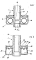
- the device shown in Fig. 1 has a pipe section 1, which is provided at both ends with connection threads 2, 3 and is intended to be in a fresh water pipe of a sanitary installation (house installation) near a quick-closing element, e.g. between the outlet of the water pipe and the entrance of a lever mixer.
- the middle part of the pipe section 1 is enclosed by an annular housing part which consists of a pot 5 formed in one piece with the pipe section 1 and a cover 6 which is sealed by sealing rings 7 on the rim of the pot and on the pipe jacket.
- the annular space 8 formed between the housing part 5, 6 and the pipe jacket is connected to the interior 12 of the pipe section 1 by two openings 10, 11 which are offset with respect to one another in the longitudinal direction of the pipe section 1.
- the interior 12 is divided by a partition 14 arranged between the two openings 10, 11, so that the water inevitably flows through the annular space 8.
- a hose ring 16 filled with compressed air and made of rubber-elastic material is arranged in the annular space 8.
- the air pressure in the hose ring 16 is approximately the same size as the flow pressure in the pipeline network.
- the rubber-elastic material can be coated with a thin layer e.g. be coated from aluminum.
- the device can easily be retrofitted into an existing sanitary installation in a bathroom, a kitchen, etc., without the masonry or the wall cladding (plates, tiles) having to be broken.
- the housing part 5 is then - aesthetically beautiful - like a usual rosette on the masonry or the wall cladding.
- the partition wall 14 can be provided with a passage so that the space 8 forms a shunt.
- the housing part enclosing the pipe section 1 consists of a ring 20 with a U-shaped cross section, the outer leg 21 of which is screwed onto an annular shoulder 22 formed integrally on the pipe section 1, and the inner leg 23 of which rests on the pipe jacket.
- a chamber 24 is formed, which is closed off by an annular membrane 25 made of rubber-elastic material from the rest, through a bore 26 with the interior 12 of the pipe section, part 27 of the annular space.
- the inner peripheral edge of the annular membrane 25 is clamped between the inner leg 23 of the ring 20 and a projection 28 formed on the tubular jacket, the outer peripheral edge is clamped between a projection 29 on the leg 21 and the angled edge 30 of the ring shoulder 22.
- the chamber 24 is filled with compressed air, the air pressure (in the case of the finished device which has not yet been used in the pipeline network) corresponding approximately to the operating pressure in the pipeline network.
- the width of the membrane ring 25 is greater than the distance between the clamping points at which its peripheral edges are clamped, so that the membrane in the same pressure Chamber 24 and the space 27 takes the bellows shape shown in the drawing. If the pressure drops, the membrane 25 bulges upward in FIG. 2, it rises, it bulges downward, and expands deeper into the chamber 24 as the pressure increases further.
- the housing part 5, 6 enclosing the pipe section 1 is designed the same as in the embodiment of FIG. 1.
- a ring 32 formed from elastic, open-cell foam is arranged in the annular space 8.
- the open-cell foam is covered with a waterproof layer 33 and this is glued to the bottom of the pot 5. (If a closed-cell foam is used instead of the open-cell foam, the coating 33 can be omitted).
- the entire section of the pipe section 1 which delimits the annular space 8 on the inside is provided with passages 34 which are arranged at small intervals from one another, so that the annular space 8 is connected to the interior 12 of the pipe section 1 as if by a grid or network.
- the pot-shaped housing part 34 enclosing the pipe section 1 has an annular projection 36, 37 on the inside of its wall 35 and the pipe section 1 on the outside of its pipe jacket.
- a ring membrane or sleeve 39 is in a Cross-section hat-shaped ring sieve 40, the inner and outer peripheral edge 41, 42 rests on the projections 36, 37.
- the housing part 34 is closed by a pressed-in cover 1 44 secured by a Seeger ring, which presses the edges 45, 46 of the sleeve 39 tightly against the housing and tube wall and the peripheral edges 41, 42 of the sieve 42.
- annular chamber 47 To fill the between the cover 44 and the sleeve 39 formed, annular chamber 47 with compressed air, a check valve 48 is provided in the cover 44.
- the air pressure in the chamber 47 of the device which has been completed but has not yet been inserted into the pipeline network is equal to or slightly less than the flow pressure in the pipeline network.
- the cross-sectionally U-shaped annular space 49 formed between the pipe and housing walls and the sieve 40 is connected to the interior 12 of the pipe section 1 by a plurality of openings 50 offset with respect to one another in the longitudinal direction of the pipe section 1.
- the sieve 40 limits the inflation of the sleeve 39, so that overstressing or overstretching is prevented, and the free U-ring space 49 between the tube and housing wall and the sleeve 39 and its hat or U cross-sectional shape result in an even pressure distribution on the cuff and a large surface of the same.
- the housing has two axially offset connecting pieces 2, 3.
- the pipe section 1 connecting the pieces 2, 3 has a flange 51 adjacent to the piece 2, in which a non-return valve (not shown) is arranged.
- a pot-shaped housing part 52 has in the middle of its base 53 an internally threaded connection piece 54, which is screwed onto an external thread of the connection piece 3.
- an annular sieve 55 which is hat-shaped in cross section, is supported by feet 56.
- a cuff which is also hat-shaped in cross section is mounted in the ring sieve 55.
- the cuff consists of a rubber-elastic material 57, which is coated on the inside with an aluminum layer 58.
- the sleeve 57, 58 and the flange 51 enclose one with compressed air through the check valve in the flange 51 filled chamber 59.
- the tightness of the chamber 59 is ensured by the fact that the edge of the sleeve 57, 58 is pressed against the flange 51 from the edge of the ring sieve 55.
- the pressure takes place when the connection piece 54 is screwed onto the connection piece 3, in that the pot base 53 presses the sieve 55 provided with the feet 56 upwards against the flange 51.
- the rubber-elastic part 57 of the sleeve suitably consists of an elastomer molded in the pressing process (for example nitrile rubber NBR, polyolefin rubber EPDM).
- the aluminum layer 58 can consist of a deep-drawn aluminum foil which is inserted into the part 57 and is preferably glued or welded (sealed) to the part 57 at least at the edge.
- the aluminum layer 58 can also be evaporated onto the sleeve part 57, either only on the inside or additionally on the outside.
- the aluminum layer 58 ensures that the air pressure in the chamber 59 is reliably maintained for a practically unlimited time, ie no air diffusion through pores of the rubber-elastic part 57 can take place.
- the aluminum foil or layer 58 is to be chosen so thin that it practically does not impair the deformability of the rubber-elastic part 57.
- the deep-drawn and deep-drawn aluminum foil can be soft-annealed after deep-drawing so that it loses the rigidity given to it by rolling and deep-drawing, ie it becomes as flexible as possible.
- the rubber-elastic part 57 could also be coated with another non-porous material (another metal or a suitable plastic).
- aluminum is particularly well suited both in terms of tightness and deformability.
- the housing consists of two parts.
- the first part has a connecting piece 2 to be screwed into a water pipe, on which a flange 60 with an external thread is formed.
- the second part has a connection piece 3 to be connected to a fitting of a fitting, which is formed in the bottom of a pot-shaped housing part 61.
- the edge of the pot-shaped housing part 61 is provided with an internal thread and screwed onto the external thread of the flange 60.
- a capsule 62 is inserted into the interior of the housing part 61.
- the capsule 62 has a lid 63, in which a filler neck or a check valve 64 is seated, and a hat-shaped sieve 65, in which a likewise hat-shaped membrane is mounted.
- the membrane consists of a rubber-elastic material 66, the inside of which is coated with an aluminum layer 67.
- the thickness and the diameter of the capsule 62 are smaller than the space between the housing part 61 and the flange 60.
- webs 68 are attached, which engage in recesses in the housing part 61 and the flange 60 and the capsule 62 keep at a distance from the flange 60 and the housing part 61 so that the water can flow from the socket 2 around the capsule 62 through the interior of the housing part 61 into the socket 3.
- the edges of the sieve 65, the membrane 66, 67 and the cover 63 are tightly glued or welded together and additionally sealed with a sealing ring 69.
- the capsule chamber enclosed by the cover 63 and the membrane 66, 67 is filled with compressed air.
- the capsule 62 is completely finished before being inserted into the housing and filled with compressed air through the filler neck 64, whereupon the filler neck is sealed with sealing compound.
- the capsule 62 is then inserted into the housing part 61 and this with the In male thread of its edge screwed onto the external thread of the flange 60.
- the edge of the membrane 66, 67 is pressed together between the edges of the cover 63 and the strainer 65, because the bottom of the housing part 61 presses the strainer 65 via the webs 68 against the cover 63 supported on the flange 60 by the webs 68.
- the tightness of the connection of the membrane 66, 67 to the cover 63 remains ensured for a practically unlimited time.
- the elastically compressible means provided in each of the devices in the housing space reduces those in domestic installations Due to the rapid closing of quick-release devices, e.g. lever mixers, pressure surges occur.
- the air cushions in the hose ring 16 and the chamber 24, 49, 59, 62 have the advantage that they absorb the pressure surge very quickly, the foam 32 has the advantage of greater friction and thus better damping of pressure vibrations.
- several elastically compressible means for. B. an air-filled hose ring and a foam ring can be arranged to achieve both rapid pressure absorption and good vibration damping. Since the space is formed in a housing part protruding radially above the pipe connection parts 2, 3, the elastically compressible means can be dimensioned sufficiently large to sufficiently reduce even very high pressure surges.
- the size of the compressible volume (the air volume in the hose ring 16 or the chambers) is decisive 24, 47, 59 or the foam volume 32) as well as the deformable surface (elastic or flexible wall 16, 25, 33, 39, 57/58, 66/67).
- the outside diameter of the housing part, in which the space for accommodating the elastically compressible means is formed is preferably at least twice as large as the outside diameter of the connecting piece.
- the outer diameter of the housing part 5, 20, 34, 52, 61 is three times the outer diameter of the connecting piece 2, 3.
- Fig. 7 shows schematically how to design the device for connecting various connectors.
- the devices 70-72 have, according to the exemplary embodiments of FIGS. 1-4 and 6 for the connection piece 2 for the water pipe, coaxial connection pieces 3 which, depending on the intended connection piece, have an external thread (piece 3 of 70) or an internal thread (piece 3 of 71 and 72 ) are executed.
- the device 73 has in the housing part 80 a coaxial to the connecting piece 2 for the water pipe 81 for screwing z. B. a corner piece.
- the devices 74-76 have axially offset connecting pieces 2, 3 and are intended for connecting hot and cold water fittings with different installation pitches, the distance between the pieces 3 of two devices 74-76 mounted next to one another being adjustable by turning the two devices accordingly.
Landscapes
- Engineering & Computer Science (AREA)
- General Engineering & Computer Science (AREA)
- Mechanical Engineering (AREA)
- Pipe Accessories (AREA)
- Pipeline Systems (AREA)
- Filling Or Discharging Of Gas Storage Vessels (AREA)
Abstract
Description
- Die Erfindung betrifft eine Vorrichtung zum Dämpfen von Druckstössen in Rohrleitungen, insbesondere Sanitärinstallationen, gemäss dem Oberbegriff des Patentanspruchs 1.
- In Rohrleitungen treten beim Absperren der strömenden Flüssigkeit bekanntlich Druckstösse auf. Die Grösse des Druckstosses hängt dabei davon ab, wie rasch das Absperren erfolgt. Bei den älteren Sanitärinstallationen (Hausinstallationen) traten nur geringe Druckstösse auf, weil die üblichen Wasserhähne (Niedershraubventile) nur langsam schliessbar waren. Bei den in neueren Installationen verwendeten Schnellschlussorganen, insbesondere Hebelmischern, kann nun aber der Durchfluss abrupt unterbrochen werden, so dass ein sehr hoher Druckstoss entsteht. Im Rahmen der Erfindung durchgeführte Untersuchungen haben gezeigt, dass beim raschen Schliessen von Hebelmischern Druckstösse von über 20 bar entstehen können. Bei derart hohen Druckstössen besteht die Gefahr von Beschädigungen der Installation, insbesondere der Armaturen und der Verbindungsstellen von Kunststoffrohren.
- Hier will die Erfindung Abhilfe schaffen. Ihr liegt die Aufgabe zugrunde, eine mühelos auch nachträglich in bestehende Installationen einsetzbare, einfache und preiswerte Vorrichtung zu schaffen, welche durch Schnellschlussorgane verursachte Druckstösse so weit reduziert, dass die Gefahr von Beschädigungen der Installation vermieden wird.
- Die erfindungsgemässe Lösung dieser Aufgabe ist Gegenstand des Patentanspruchs 1. Bevorzugte Ausführungsarten sind in den Patentansprüchen 2 bis 14 umschrieben.
- Im folgenden werden anhand der Zeichnung Ausführungsbeispiele der Erfindung näher beschrieben. Es zeigen:
- Fig. 1 einen Längsschnitt durch eine Vorrichtung zum Dämpfen von Druckstössen,
- Fig. 2 - Fig. 6 Längsschnitte durch fünf Varianten der Vorrichtung, und
- Fig. 7 schematische Darstellungen von mit unterschiedlichen Anschlussstutzen ausgerüsteten Vorrichtungen mit Beispielen von an die Stutzen anzuschliessenden Anschlussstücken.
- Die in Fig. 1 dargestellte Vorrichtung hat ein Rohrleitungsstück 1, das an beiden Enden mit Anschlussgewinden 2, 3 versehen und dazu bestimmt ist, in eine Frischwasserleitung einer Sanitärinstallation (Hausinstallation) nahe einem Schnellschlussorgan, z.B. zwischen den Ausgang der Wasserleitung und den Eingang eines Hebelmischers, eingesetzt zu werden. Der mittlere Teil des Rohrleitungsstücks 1 ist von einem ringförmigen Gehäuseteil umschlossen, der aus einem einstückig mit dem Rohrleitungsstück 1 gebildeten Topf 5 und einem Deckel 6 besteht, der durch Dichtungsringe 7 am Topfrand und am Rohrmantel abgedichtet ist. Der zwischen dem Gehäuseteil 5, 6 und dem Rohrmantel gebildete Ringraum 8 steht durch zwei in Längsrichtung des Rohrleitungsstücks 1 gegeneinander versetzte Oeffnungen 10, 11 mit dem Innenraum 12 des Rohrleitungsstücks 1 in Verbindung. Der Innenraum 12 ist durch eine zwischen den beiden Oeffnungen 10, 11 angeordnete Trennwand 14 unterteilt, so dass das Wasser zwangsläufig durch den Ringraum 8 strömt. Im Ringraum 8 ist ein mit Druckluft gefüllter Schlauchring 16 aus gummielastischem Material angeordnet. Der Luftdruck im Schlauchring 16 ist etwa gleich gross bemessen wie der Fliessdruck im Rohrleitungsnetz. Um die Dichtigkeit des Schlauchrings auch über sehr lange Zeit sicherzustellen, d. h. eine Diffusion der Luft durch den Schlauchring zu verhindern, kann das gummmielastische Material mit einer dünnen Schicht z.B. aus Aluminium beschichtet sein.
- Die Vorrichtung kann ohne weiteres nachträglich in eine bestehende Sanitärinstallation eines Badezimmers, einer Küche usw. eingesetzt werden, ohne dass das Mauerwerk oder die Mauerverkleidung (Platten, Kacheln) aufgebrochen werden müsste. Man braucht lediglich das Anschlussstück der Armatur von der Wasserleitung abzuschrauben, die Vorrichtung 1 mit dem Anschlussgewinde 2 in die Wasserleitung einzuschrauben bis der Gehäuseteil 5 mit seiner Deckelseite 6 am Mauerwerk bzw. der Mauerverkleidung anliegt, und die Armatur mit Hilfe eines entsprechend bemessenen, in das Anschlussgewinde 3 eingeschraubten Anschlussstücks mit der Vorrichtung zu verbinden. Der Gehäuseteil 5 liegt dann - ästhetisch schön - wie eine übliche Rosette auf dem Mauerwerk bzw. der Mauerverkleidung.
- Um den Strömungswiderstand herabzusetzen, kann die Trennwand 14 mit einem Durchlass versehen sein, so dass der Raum 8 einen Nebenschluss bildet.
- Bei der in Fig. 2 dargestellten Variante besteht der das Rohrleitungsstück 1 umschliessende Gehäuseteil aus einem im Querschnitt U-förmigen Ring 20, dessen äusserer Schenkel 21 auf eine einstückig am Rohrstück 1 gebildete Ringschulter 22 geschraubt ist, und dessen innerer Schenkel 23 am Rohrmantel anliegt. Im durch den Ring 20 und die Ringschulter 22 umschlossenen Ringraum ist eine Kammer 24 gebildet, welche durch eine ringförmige Membran 25 aus gummielastischem Material vom übrigen, durch eine Bohrung 26 mit dem Inneren 12 des Rohrleitungsstücks in Verbindung stehenden Teil 27 des Ringraums abgeschlossen ist. Der innere Umfangsrand der ringförmigen Membran 25 ist zwischen dem inneren Schenkel 23 des Rings 20 und einem am Rohrmantel gebildeten Vorsprung 28, der äussere Umfangsrand ist zwischen einem Vorsprung 29 am Schenkel 21 und dem abgewinkelten Rand 30 der Ringschulter 22 festgeklemmt. Die Kammer 24 ist mit Druckluft gefüllt, wobei der Luftdruck (bei der fertiggestellten, aber noch nicht ins Rohrleitungsnetz eingesetzten Vorrichtung) etwa dem Betriebsdruck im Rohrleitungsnetz entspricht. Die Breite des Membranrings 25 ist grösser als der Abstand zwischen den Klemmstellen, an denen ihre Umfangsränder eingeklemmt sind, so dass die Membran bei gleichem Druck in der Kammer 24 und dem Raum 27 die in der Zeichnung dargestellte Balgform einnimmmt. Sinkt der Druck, baucht sich die Membran 25 in Fig. 2 nach oben aus, steigt er, baucht sie sich nach unten aus und dehnt sich bei weiterem Anstieg des Drucks immer tiefer in die Kammer 24 hinein.
- Bei der in Fig. 3 dargestellten Variante ist der das Rohrleitungsstück 1 umschliessende Gehäuseteil 5, 6 gleich wie bei der Ausführungsform von Fig. 1 ausgebildet. Im Ringraum 8 ist anstelle des mit Luft gefüllten Schlauchrings 16 ein aus elastischem, offenzelligem Schaumstoff gebildeter Ring 32 angeordnet. Der offenzellige Schaumstoff ist mit einer wasserdichten Schicht 33 überzogen und diese ist an den Boden des Topfes 5 geklebt. (Wenn anstelle des offenzelligen Schaumstoffs ein geschlossenzelliger Schaumstoff verwendet wird, kann der Ueberzug 33 entfallen). Der gesamte, den Ringraum 8 innen begrenzende Abschnitt des Rohrleitungsstücks 1 ist mit in kleinen Abständen voneinander angeordneten Durchlässen 34 versehen, so dass der Ringraum 8 wie durch ein Gitter oder Netz mit dem Inneren 12 des Rohrleitungsstücks 1 in Verbindung steht.
- Bei der in Fig. 4 dargestellten Variante haben der das Rohrleitungsstück 1 umschliessende, topfförmige Gehäuseteil 34 an der Innenseite seiner Wandung 35 und das Rohrleitungsstück 1 an der Aussenseite seines Rohrmantels je einen ringförmigen Vorsprung 36, 37. Eine Ringmembran oder Manschette 39 ist in einem im Querschnitt hutförmigen Ringsieb 40 gefasst, dessen innerer und äusserer Umfangsrand 41, 42 auf den Vorsprüngen 36, 37 aufliegt. Der Gehäuseteil 34 ist durch einen eingepressten und durch einen Seeger-Ring gesicherten Decke1 44 abgeschlossen, der die Ränder 45, 46 der Manschette 39 dicht an die Gehäuse- und Rohrwandung sowie die Umfangsränder 41, 42 des Siebs 42 presst. Zum Füllen der zwischen dem Deckel 44 und der Manschette 39 gebildeten, ringförmigen Kammer 47 mit Druckluft ist im Deckel 44 ein Rückschlagventil 48 vorgesehen. Der Luftdruck in der Kammer 47 der fertiggestellten, aber noch nicht ins Rohrleitungsnetz eingesetzten Vorrichtung ist gleich oder etwas kleiner als der Fliessdruck im Rohrleitungsnetz bemessen. Der zwischen der Rohr- und Gehäusewandung sowie dem Sieb 40 gebildete, im Querschnitt U-förmige Ringraum 49 ist durch mehrere, in Längsrichtung des Rohrleitungsstücks 1 gegeneinander versetzte Oeffnungen 50 mit dem Innenraum 12 des Rohrleitungsstücks 1 verbunden. Das Sieb 40 begrenzt das Aufblähen der Manschette 39, so dass eine Ueberbeanspruchung bzw. Ueberdehnung verhindert wird, und der freie U-Ringraum 49 zwischen der Rohr- und Gehäusewandung sowie der Manschette 39 und deren Hut- bzw. U-Querschnittsform ergeben eine gleichmässige Druckverteilung auf die Manschette sowie eine grosse Oberfläche derselben.
- Bei der in Fig. 5 dargestellten Variante hat das Gehäuse zwei axial gegeneinander versetzte Anschlussstutzen 2, 3. Das die Stutzen 2, 3 verbindende Rohrstück 1 hat angrenzend an den Stutzen 2 einen Flansch 51, in dem ein (nicht dargestelltes) Rückschlagventil angeordnet ist. Ein topfförmiger Gehäuseteil 52 hat in der Mitte seines Bodens 53 einen mit einem Innengewinde versehenen Stutzen 54, der auf ein Aussengewinde des Anschlussstutzens 3 geschraubt ist. Auf der Innenseite des Topfbodens 53 ist ein im Querschnitt hutförmiges Ringsieb 55 mittels Füssen 56 abgestützt. Im Ringsieb 55 ist eine im Querschnitt ebenfalls hutförmige Manschette gelagert. Die Manschette besteht aus einem gummielastischen Material 57, das an der Innenseite mit einer Aluminiumschicht 58 beschichtet ist. Die Manschette 57, 58 und der Flansch 51 umschliessen eine durch das Rückschlagventil im Flansch 51 mit Druckluft gefüllte Kammer 59. Die Dichtigkeit der Kammer 59 ist dadurch gewährleistet, dass der Rand der Manschette 57, 58 vom Rand des Ringsiebs 55 an den Flansch 51 gepresst ist. Die Pressung erfolgt beim Anschrauben des Stutzens 54 auf den Anschlussstutzen 3, indem der Topfboden 53 das mit den Füssen 56 versehene Sieb 55 nach oben gegen den Flansch 51 presst. Der gummielastische Teil 57 der Manschette besteht zweckmässig aus einem im Pressverfahren geformten Elastomer (z.B. Nitrilkautschuk NBR, Polyolefinkautschuk EPDM). Die Aluminiumschicht 58 kann aus einer tiefgezogenen Aluminiumfolie bestehen, die in den Teil 57 eingesetzt und vorzugsweise zumindest am Rand mit dem Teil 57 verklebt oder verschweisst (versiegelt) ist. Die Aluminiumschicht 58 kann auch auf den Manschettenteil 57 aufgedampft sein, entweder nur an der Innenseite oder zusätzlich auch noch an der Aussenseite. Die Aluminiumschicht 58 gewährleistet, dass der Luftdruck in der Kammer 59 während praktisch unbegrenzter Zeit zuverlässig aufrechterhalten wird, d.h. keine Luftdiffusion durch Poren des gummielastischen Teils 57 stattfinden kann. Die Aluminiumfolie bzw. -schicht 58 ist dabei so dünn zu wählen, dass sie die Verformbarkeit des gummielastischen Teils 57 praktisch nicht beeinträchtigt. Die auf eine sehr geringe Dicke ausgewalzte und tiefgezogene Aluminiumfolie kann nach dem Tiefziehen weichgeglüht werden, damit sie die ihr durch das Auswalzen und Tiefziehen verliehene Steifigkeit wieder verliert, d.h möglichst gut biegsam wird. Der gummielastische Teil 57 könnte aus den genannten Gründen auch mit einem anderen porenfreien Material (einem anderen Metall oder einem geeigneten Kunststoff) beschichtet sein. Aluminium ist aber sowohl hinsichtlich der Dichtigkeit als auch der Verformbarkeit besonders gut geeignet.
- Bei der in Fig. 6 dargestellten Variante besteht das Gehäuse aus zwei Teilen. Der erste Teil hat einen in eine Wasserleitung zu schraubenden Anschlussstutzen 2, an dem ein Flansch 60 mit Aussengewinde gebildet ist. Der zweite Teil hat einen an ein Anschlussstück einer Armatur anzuschliessenden Stutzen 3, der im Boden eines topfförmigen Gehäuseteils 61 gebildet ist. Der Rand des topfförmigen Gehäuseteils 61 ist mit einem Innengewinde versehen und auf das Aussengewinde des Flanschs 60 geschraubt. In den Innenraum des Gehäuseteils 61 ist eine Kapsel 62 eingesetzt. Die Kapsel 62 hat einen Deckel 63, in dem ein Füllstützen oder ein Rückschlagventil 64 sitzt, und ein hutförmiges Sieb 65, in dem eine ebenfalls hutförmige Membran gelagert ist. Die Membran besteht ebenso wie die Manschette 57, 58 in Fig. 5 aus einem gummielastischen Material 66, dessen Innenseite mit einer Aluminiumschicht 67 beschichtet ist. Die Dicke und der Durchmesser der Kapsel 62 sind kleiner bemessen als der Raum zwischen dem Gehäuseteil 61 und dem Flansch 60. Am Deckel 63 und am Siebboden 65 sind Stege 68 angebracht, die in Vertiefungen des Gehäuseteils 61 und des Flansches 60 greifen und die Kapsel 62 in einem Abstand vom Flansch 60 und dem Gehäuseteil 61 halten, so dass das Wasser vom Stutzen 2 um die Kapsel 62 herum durch den Innenraum des Gehäuseteils 61 in den Stutzen 3 strömen kann. Die Ränder des Siebs 65, der Membran 66, 67 und des Deckels 63 sind dicht miteinander verklebt oder verschweisst und zusätzlich mit einem Dichtungsring 69 abgedichtet. Die vom Deckel 63 und der Membran 66, 67 umschlossene Kapselkammer ist mit Druckluft gefüllt.
- Die Kapsel 62 wird vor dem Einsetzen in das Gehäuse vollständig fertiggestellt und durch den Einfüllstutzen 64 mit Druckluft gefüllt, worauf der Einfüllstutzen mit Dichtungsmasse versiegelt wird. Die Kapsel 62 wird dann in den Gehäuseteil 61 eingesetzt und dieser mit dem In nengewinde seines Rands auf das Aussengewinde des Flanschs 60 geschraubt. Dabei wird der Rand der Membran 66, 67 zwischen den Rändern des Deckels 63 und des Siebs 65 zusammengepresst, weil der Boden des Gehäuseteils 61 das Sieb 65 über die Stege 68 gegen den mit den Stegen 68 am Flansch 60 abgestützten Deckel 63 presst. Durch diese Verpressung bleibt die Dichtigkeit der Verbindung der Membran 66, 67 mit dem Deckel 63 über praktisch unbegrenzte Zeit gesichert.
- Das in jeder der Vorrichtungen im Gehäuseraum vorgesehene, elastisch zusammendrückbare Mittel (der mit Luft gefüllte Schlauchring 16 in Fig. 1; das Luftpolster in der Kammer 24 mit der Membran 25 in Fig. 2; der Schaumstoffring 32 in Fig. 3; das Luftpolster in der Kammer 47 mit der Membran 39 in Fig. 4; das Luftpolster in der Kammer 59 mit der Manschette 57, 58 in Fig. 5; das Luftpolster in der Kapsel 62 mit der Membran 66, 67 in Fig. 6) reduziert die in Hausinstallationen infolge des raschen Schliessens von Schnellverschlussorganen, z.B. Hebelmischern, entstehenden Druckstösse. Die Luftpolster im Schlauchring 16 und der Kammer 24, 49, 59, 62 haben den Vorteil, dass sie den Druckstoss sehr rasch aufnehmen, der Schaumstoff 32 hat den Vorteil einer grösseren Reibung und damit besseren Dämpfung von Druckschwingungen. Im Gehäuseraum können auch mehrere elastisch zusammendrückbare Mittel, z. B. ein mit Luft gefüllter Schlauchring und ein Schaumstoffring angeordnet sein, um sowohl eine rasche Druckaufnahme als auch eine gute Schwingungsdämpfung zu erzielen. Da der Raum in einem radial über die Rohranschlussteile 2, 3 vorstehenden Gehäuseteil gebildet ist, lässt sich das elastisch zusammendrückbare Mittel genügend gross bemessen, um auch sehr hohe Druckstösse ausreichend zu reduzieren. Für die Druckreduzierung kommt es entscheidend sowohl auf die Grösse des zusammenpressbaren Volumens (des Luftvolumens im Schlauchring 16 bzw. den Kammern 24, 47, 59 oder des Schaumstoffvolumens 32) als auch der verformbaren Fläche (elastische bzw. biegsame Wandung 16, 25, 33, 39, 57/58, 66/67) an. Die Druckstossdämpfung ist umso besser, je grösser das Volumen und die verformbare Fläche sind. Vorzugsweise ist der Aussendurchmesser des Gehäuseteils, in dem der Raum für die Aufnahme des elastisch zusammendrückbaren Mittels gebildet ist, mindestens doppelt so gross wie der Aussendurchmesser der Anschlussstutzen. Bei den Ausführungsbeispielen beträgt der Aussendurchmesser des Gehäuseteils 5, 20, 34, 52, 61 das Dreifache des Aussendurchmessers der Stutzen 2, 3. Versuche haben gezeigt, dass z. B. mit der Ausführungsform von Fig. 4 Druckspitzen von 26 bar auf 8,5 bar reduziert werden. Der Gehäuseteil 5, 20, 34, 52, 61 kann, wie dargestellt, formschön gestaltet und ausserhalb des Mauerwerks wie eine Rosette montiert werden. Die dargestellten Vorrichtungen können auch nachträglich leicht ohne Aenderung der Installation eingebaut werden.
- Fig. 7 zeigt schematisch, wie man die Vorrichtung zum Anschluss verschiedener Anschlussstücke ausgestalten kann. Die Vorrichtungen 70-72 haben entsprechend den Ausführungsbeispielen von Fig. 1-4 und 6 zum Anschlussstutzen 2 für die Wasserleitung koaxiale Anschlussstutzen 3, die je nach dem vorgesehenen Anschlussstück mit Aussengewinde (Stutzen 3 von 70) oder Innengewinde (Stutzen 3 von 71 und 72) ausgeführt sind. Die Vorrichtung 73 hat im Gehäuseteil 80 ein zum Anschlussstutzen 2 für die Wasserleitung koaxiales Innengewinde 81 für das Einschrauben z. B. eines Eckstücks. Die Vorrichtungen 74-76 haben axial gegeneinander versetzte Anschlussstutzen 2, 3 und sind zum Anschluss von Warm- und Kaltwasserarmaturen mit unterschiedlichem Installationsstichmass bestimmt, wobei der Abstand der Stutzen 3 zweier nebeneinander montierter Vorrichtungen 74-76 durch entsprechendes Drehen der beiden Vorrichtungen einstellbar ist.
Claims (14)
Priority Applications (1)
| Application Number | Priority Date | Filing Date | Title |
|---|---|---|---|
| AT87107342T ATE56513T1 (de) | 1986-06-11 | 1987-05-20 | Vorrichtung zum daempfen von druckstoessen in rohrleitungen, insbesondere sanitaerinstallationen. |
Applications Claiming Priority (2)
| Application Number | Priority Date | Filing Date | Title |
|---|---|---|---|
| CH2362/86 | 1986-06-11 | ||
| CH236286 | 1986-06-11 |
Related Child Applications (2)
| Application Number | Title | Priority Date | Filing Date |
|---|---|---|---|
| EP90103412.4 Division-Into | 1987-05-20 | ||
| EP19900103412 Division EP0373155A3 (de) | 1986-06-11 | 1987-05-20 | Vorrichtung zum Dämpfen von Druckstössen in Rohrleitungen, insbesondere Sanitärinstallationen |
Publications (2)
| Publication Number | Publication Date |
|---|---|
| EP0249067A1 true EP0249067A1 (de) | 1987-12-16 |
| EP0249067B1 EP0249067B1 (de) | 1990-09-12 |
Family
ID=4232019
Family Applications (2)
| Application Number | Title | Priority Date | Filing Date |
|---|---|---|---|
| EP87107342A Expired - Lifetime EP0249067B1 (de) | 1986-06-11 | 1987-05-20 | Vorrichtung zum Dämpfen von Druckstössen in Rohrleitungen, insbesondere Sanitärinstallationen |
| EP19900103412 Withdrawn EP0373155A3 (de) | 1986-06-11 | 1987-05-20 | Vorrichtung zum Dämpfen von Druckstössen in Rohrleitungen, insbesondere Sanitärinstallationen |
Family Applications After (1)
| Application Number | Title | Priority Date | Filing Date |
|---|---|---|---|
| EP19900103412 Withdrawn EP0373155A3 (de) | 1986-06-11 | 1987-05-20 | Vorrichtung zum Dämpfen von Druckstössen in Rohrleitungen, insbesondere Sanitärinstallationen |
Country Status (8)
| Country | Link |
|---|---|
| US (2) | US4821777A (de) |
| EP (2) | EP0249067B1 (de) |
| JP (1) | JPS62292990A (de) |
| AT (1) | ATE56513T1 (de) |
| AU (1) | AU599984B2 (de) |
| CA (1) | CA1271686A (de) |
| DE (1) | DE3764872D1 (de) |
| ES (1) | ES2018199B3 (de) |
Cited By (1)
| Publication number | Priority date | Publication date | Assignee | Title |
|---|---|---|---|---|
| EP0660906B1 (de) * | 1993-06-22 | 1998-08-12 | Gevipi A.G. | Schwingungs- und geräuschabsorbierende vorrichtung für ein hydraulisches system |
Families Citing this family (23)
| Publication number | Priority date | Publication date | Assignee | Title |
|---|---|---|---|---|
| JPH02128895U (de) * | 1989-03-31 | 1990-10-24 | ||
| JPH0398395U (de) * | 1990-01-26 | 1991-10-11 | ||
| US5133387A (en) * | 1990-09-20 | 1992-07-28 | The Aro Corporation | Fluid pulsation dampener having spiral grooved bellows |
| US5215124A (en) * | 1990-10-23 | 1993-06-01 | Honda Giken Kogyo Kabushiki Kaisha | Accumulator |
| FR2697071B1 (fr) * | 1992-10-20 | 1994-11-18 | Jacques Compienne | Accumulateur anti bélier en ligne. |
| DE4311263A1 (de) * | 1993-04-06 | 1994-10-13 | Bosch Gmbh Robert | Dämpfungseinrichtung insbesondere für ein hydraulisches Bremssystem |
| JP2827160B2 (ja) * | 1995-08-11 | 1998-11-18 | 株式会社タブチ | 水撃防止継手及びそれを組み込んだ配管構造 |
| US5819799A (en) * | 1996-05-10 | 1998-10-13 | The Lee Company | Method and apparatus for rapid fluid dispensing |
| US5894861A (en) * | 1998-04-23 | 1999-04-20 | Siemens Automotive Corporation | Damper dry ice charge |
| US6138499A (en) * | 1998-08-27 | 2000-10-31 | Sun Electric Europe B.V. | Exhaust emission analysis system incorporating pulse dampening |
| US6854447B2 (en) * | 2001-12-14 | 2005-02-15 | Siemens Vdo Automotive Corp. | Corrugated internal fuel rail damper |
| US6672286B2 (en) | 2001-12-14 | 2004-01-06 | Siemens Automotive Corporation | Corrugated fuel rail damper |
| GB2431965B (en) * | 2005-11-01 | 2008-07-23 | Aker Kvaerner Subsea Ltd | Subsea modules including hydraulic accumulators |
| US7874317B1 (en) * | 2007-05-18 | 2011-01-25 | Vadim Gennadyevich Kulikov | Micro pipeline pressure stabilization apparatus |
| US8114299B2 (en) * | 2008-02-28 | 2012-02-14 | Cummins Filtration Ip, Inc. | Filter with flow surge protection and method of protecting filter from flow surge |
| US7694664B1 (en) | 2009-01-09 | 2010-04-13 | Robert Bosch Gmbh | Fuel rail damper |
| US8307855B2 (en) * | 2009-07-07 | 2012-11-13 | King Saud University | Fluid pressure spike suppression device |
| DE102010062855A1 (de) * | 2010-12-10 | 2012-07-19 | Continental Automotive Gmbh | Dämpfungsvorrichtung und Kraftstoffsystem für eine Brennkraftmaschine |
| DE102011008467B4 (de) * | 2011-01-13 | 2014-01-02 | Continental Automotive Gmbh | Injektor mit Druckausgleichsmitteln |
| US9702495B2 (en) | 2014-05-20 | 2017-07-11 | Amtrol Licensing Inc. | Multi-layered gas-filled bladder for accommodating changes in fluid characteristics within a fluid delivery system |
| US9366373B2 (en) * | 2014-05-20 | 2016-06-14 | Amtrol Licensing Inc. | Pressure absorber for a fluid system and method of use |
| CN106931173A (zh) * | 2015-12-30 | 2017-07-07 | 上海袋式除尘配件有限公司 | 一种脉冲阀用密封装置 |
| FR3074541B1 (fr) * | 2017-12-01 | 2019-10-18 | Safran Aircraft Engines | Accumulateur integre a une canalisation de carburant |
Citations (4)
| Publication number | Priority date | Publication date | Assignee | Title |
|---|---|---|---|---|
| US4186775A (en) * | 1975-10-07 | 1980-02-05 | Tozen Sangyo Co., Ltd. | Water hammer shock absorber |
| FR2443637A1 (fr) * | 1978-12-04 | 1980-07-04 | Liquidonics Inc | Dispositif amortisseur de pulsations |
| US4287917A (en) * | 1978-11-17 | 1981-09-08 | Knecht Filterwerke Gmbh | Diaphragm device for damping vibrations in flowing liquids |
| US4523612A (en) * | 1983-04-15 | 1985-06-18 | The United States Of America As Represented By The United States Department Of Energy | Apparatus and method for suppressing vibration and displacement of a bellows |
Family Cites Families (19)
| Publication number | Priority date | Publication date | Assignee | Title |
|---|---|---|---|---|
| US2677393A (en) * | 1950-03-09 | 1954-05-04 | Byron Jackson Co | Radially expanding bellows |
| US2725078A (en) * | 1951-06-27 | 1955-11-29 | Walter P Glancy | Flexible liner assembly for a fluid pressure device |
| US2896667A (en) * | 1956-07-27 | 1959-07-28 | Westinghouse Air Brake Co | Dampener for pipe lines |
| US2968319A (en) * | 1957-10-21 | 1961-01-17 | Melvin A Ball | Pulsation dampener |
| US3061039A (en) * | 1957-11-14 | 1962-10-30 | Joseph J Mascuch | Fluid line sound-absorbing structures |
| US3230975A (en) | 1959-12-09 | 1966-01-25 | Mercier Olaer Patent Corp | Composite movable partition for pressure vessel |
| US3422853A (en) * | 1965-10-23 | 1969-01-21 | Zurn Ind Inc | Water hammer arrester with controlled orifice |
| US3556159A (en) * | 1969-05-06 | 1971-01-19 | William J Bleasdale | Surge cushioning apparatus for pressure systems |
| US3621882A (en) | 1970-02-25 | 1971-11-23 | Harry P Kupiec | Inline, through-flow pressure compensator and accumulator |
| US4129025A (en) | 1977-02-25 | 1978-12-12 | Textron Inc. | Method of fabricating an expulsion tank diaphragm |
| US4213545A (en) * | 1978-09-20 | 1980-07-22 | Textron, Inc. | Expanding bellows for expulsion tank |
| US4298030A (en) * | 1979-08-15 | 1981-11-03 | Normand Trust | Adjustable pulse dampener |
| DE3012079A1 (de) * | 1980-03-28 | 1981-10-08 | Wabco Fahrzeugbremsen Gmbh, 3000 Hannover | Druckbehaelter |
| AU7623681A (en) * | 1980-10-16 | 1982-04-22 | Zip Heaters (Australia) Pty Limited | Water hammer reducer |
| US4552182A (en) * | 1983-04-21 | 1985-11-12 | Varian Associates, Inc. | Hydraulic pulse dampener employing two stiff diaphragms and nesting members |
| DE3478131D1 (en) * | 1983-11-11 | 1989-06-15 | Chauvier Daniel J V D | A shock damper for automatic swimming pool cleaning apparatus |
| US4628964A (en) * | 1985-05-08 | 1986-12-16 | Nobuyuki Sugimura | Background device for separating member in accumulator chamber |
| DE3667816D1 (de) * | 1985-08-16 | 1990-02-01 | Rockwell International Corp | Mit helium gefuellter hydraulischer speicher. |
| DE3628608A1 (de) * | 1986-08-22 | 1988-03-03 | Bosch Gmbh Robert | Elastische trennwand |
-
1987
- 1987-05-20 EP EP87107342A patent/EP0249067B1/de not_active Expired - Lifetime
- 1987-05-20 EP EP19900103412 patent/EP0373155A3/de not_active Withdrawn
- 1987-05-20 DE DE8787107342T patent/DE3764872D1/de not_active Expired - Fee Related
- 1987-05-20 ES ES87107342T patent/ES2018199B3/es not_active Expired - Lifetime
- 1987-05-20 AT AT87107342T patent/ATE56513T1/de not_active IP Right Cessation
- 1987-06-02 AU AU73745/87A patent/AU599984B2/en not_active Ceased
- 1987-06-03 US US07/056,969 patent/US4821777A/en not_active Expired - Fee Related
- 1987-06-04 CA CA000538903A patent/CA1271686A/en not_active Expired - Fee Related
- 1987-06-05 JP JP62140166A patent/JPS62292990A/ja active Pending
-
1988
- 1988-12-27 US US07/289,725 patent/US4911204A/en not_active Expired - Fee Related
Patent Citations (4)
| Publication number | Priority date | Publication date | Assignee | Title |
|---|---|---|---|---|
| US4186775A (en) * | 1975-10-07 | 1980-02-05 | Tozen Sangyo Co., Ltd. | Water hammer shock absorber |
| US4287917A (en) * | 1978-11-17 | 1981-09-08 | Knecht Filterwerke Gmbh | Diaphragm device for damping vibrations in flowing liquids |
| FR2443637A1 (fr) * | 1978-12-04 | 1980-07-04 | Liquidonics Inc | Dispositif amortisseur de pulsations |
| US4523612A (en) * | 1983-04-15 | 1985-06-18 | The United States Of America As Represented By The United States Department Of Energy | Apparatus and method for suppressing vibration and displacement of a bellows |
Cited By (1)
| Publication number | Priority date | Publication date | Assignee | Title |
|---|---|---|---|---|
| EP0660906B1 (de) * | 1993-06-22 | 1998-08-12 | Gevipi A.G. | Schwingungs- und geräuschabsorbierende vorrichtung für ein hydraulisches system |
Also Published As
| Publication number | Publication date |
|---|---|
| EP0249067B1 (de) | 1990-09-12 |
| US4911204A (en) | 1990-03-27 |
| US4821777A (en) | 1989-04-18 |
| EP0373155A2 (de) | 1990-06-13 |
| ATE56513T1 (de) | 1990-09-15 |
| AU7374587A (en) | 1987-12-17 |
| JPS62292990A (ja) | 1987-12-19 |
| EP0373155A3 (de) | 1991-06-12 |
| ES2018199B3 (es) | 1991-04-01 |
| DE3764872D1 (de) | 1990-10-18 |
| AU599984B2 (en) | 1990-08-02 |
| CA1271686A (en) | 1990-07-17 |
Similar Documents
| Publication | Publication Date | Title |
|---|---|---|
| EP0249067B1 (de) | Vorrichtung zum Dämpfen von Druckstössen in Rohrleitungen, insbesondere Sanitärinstallationen | |
| DE10011505A1 (de) | Sanitärarmatur, insbesondere Küchenmischer | |
| EP2865815B1 (de) | Sanitäre Auslaufarmatur | |
| EP2753853A1 (de) | Sanitär-einhebel-waschtischarmatur | |
| EP0446179B1 (de) | Doppelrohrverbindung an Kunststoffrohren | |
| DE2328361A1 (de) | Mischarmatur, insbesondere wasserhahn fuer warmes und kaltes wasser | |
| EP0818585A2 (de) | Unterputz-Anschlussstück | |
| EP3194667B1 (de) | Abflussvorrichtung und becken mit einer solchen abflussvorrichtung | |
| DE202012103132U1 (de) | Ablaufanordnung für Wasserarmaturen | |
| DE102017123765A1 (de) | Adapter zum Anschluss einer Ventil- oder Spülarmatur an eine Rohrleitung und System mit einem solchen Adapter und einem Vorwandgestellelement | |
| EP0441151A1 (de) | Wasserzapfarmatur mit Rücksaugsicherung | |
| AT518018B1 (de) | Siphon mit getrennten Kammern | |
| DE1959030A1 (de) | Druckstoßdampfer fur Flussigkeits leitungen | |
| DE3732565C2 (de) | ||
| DE3626337C2 (de) | Druckstoßdämpfer für Wasserleitungen | |
| EP2628864B1 (de) | Spül- und Abdrückvorrichtung für eine Anschlussarmatur | |
| EP3578723A1 (de) | Geruchsverschluss für einen wasserablauf sowie wasserablauf mit geruchsverschluss | |
| DE3330963C2 (de) | ||
| DE2723082C2 (de) | Schalldämpfungseinrichtung in Sanitärarmaturen | |
| DE2705117A1 (de) | Anschlussarmatur fuer heizkoerper oder dergleichen | |
| DE3937778A1 (de) | Alarmventilstation | |
| DE3611452C1 (en) | Pipe disconnector | |
| DE60215776T2 (de) | Vorrichtung für rohrleitungssystem | |
| EP3267133A1 (de) | Wasserfilterbaugruppe und damit ausgestattetes kältegerät | |
| EP1832687A1 (de) | Trichtersifon |
Legal Events
| Date | Code | Title | Description |
|---|---|---|---|
| PUAI | Public reference made under article 153(3) epc to a published international application that has entered the european phase |
Free format text: ORIGINAL CODE: 0009012 |
|
| AK | Designated contracting states |
Kind code of ref document: A1 Designated state(s): AT CH DE ES FR IT LI NL SE |
|
| 17P | Request for examination filed |
Effective date: 19880318 |
|
| 17Q | First examination report despatched |
Effective date: 19890317 |
|
| GRAA | (expected) grant |
Free format text: ORIGINAL CODE: 0009210 |
|
| AK | Designated contracting states |
Kind code of ref document: B1 Designated state(s): AT CH DE ES FR IT LI NL SE |
|
| REF | Corresponds to: |
Ref document number: 56513 Country of ref document: AT Date of ref document: 19900915 Kind code of ref document: T |
|
| XX | Miscellaneous (additional remarks) |
Free format text: TEILANMELDUNG 90103412.4 EINGEREICHT AM 20/05/87. |
|
| REF | Corresponds to: |
Ref document number: 3764872 Country of ref document: DE Date of ref document: 19901018 |
|
| ITF | It: translation for a ep patent filed | ||
| ET | Fr: translation filed | ||
| PLBE | No opposition filed within time limit |
Free format text: ORIGINAL CODE: 0009261 |
|
| STAA | Information on the status of an ep patent application or granted ep patent |
Free format text: STATUS: NO OPPOSITION FILED WITHIN TIME LIMIT |
|
| 26N | No opposition filed | ||
| ITTA | It: last paid annual fee | ||
| PGFP | Annual fee paid to national office [announced via postgrant information from national office to epo] |
Ref country code: FR Payment date: 19930429 Year of fee payment: 7 |
|
| PGFP | Annual fee paid to national office [announced via postgrant information from national office to epo] |
Ref country code: AT Payment date: 19930505 Year of fee payment: 7 |
|
| PGFP | Annual fee paid to national office [announced via postgrant information from national office to epo] |
Ref country code: SE Payment date: 19930518 Year of fee payment: 7 |
|
| PGFP | Annual fee paid to national office [announced via postgrant information from national office to epo] |
Ref country code: CH Payment date: 19930524 Year of fee payment: 7 |
|
| PGFP | Annual fee paid to national office [announced via postgrant information from national office to epo] |
Ref country code: ES Payment date: 19930527 Year of fee payment: 7 |
|
| PGFP | Annual fee paid to national office [announced via postgrant information from national office to epo] |
Ref country code: NL Payment date: 19930531 Year of fee payment: 7 |
|
| PGFP | Annual fee paid to national office [announced via postgrant information from national office to epo] |
Ref country code: DE Payment date: 19930722 Year of fee payment: 7 |
|
| PG25 | Lapsed in a contracting state [announced via postgrant information from national office to epo] |
Ref country code: AT Effective date: 19940520 |
|
| PG25 | Lapsed in a contracting state [announced via postgrant information from national office to epo] |
Ref country code: SE Effective date: 19940521 Ref country code: ES Free format text: LAPSE BECAUSE OF NON-PAYMENT OF DUE FEES Effective date: 19940521 |
|
| PG25 | Lapsed in a contracting state [announced via postgrant information from national office to epo] |
Ref country code: LI Effective date: 19940531 Ref country code: CH Effective date: 19940531 |
|
| PG25 | Lapsed in a contracting state [announced via postgrant information from national office to epo] |
Ref country code: NL Effective date: 19941201 |
|
| NLV4 | Nl: lapsed or anulled due to non-payment of the annual fee | ||
| EUG | Se: european patent has lapsed |
Ref document number: 87107342.5 Effective date: 19941210 |
|
| PG25 | Lapsed in a contracting state [announced via postgrant information from national office to epo] |
Ref country code: FR Effective date: 19950131 |
|
| REG | Reference to a national code |
Ref country code: CH Ref legal event code: PL |
|
| PG25 | Lapsed in a contracting state [announced via postgrant information from national office to epo] |
Ref country code: DE Effective date: 19950201 |
|
| EUG | Se: european patent has lapsed |
Ref document number: 87107342.5 |
|
| REG | Reference to a national code |
Ref country code: FR Ref legal event code: ST |
|
| REG | Reference to a national code |
Ref country code: ES Ref legal event code: FD2A Effective date: 19990201 |
|
| PG25 | Lapsed in a contracting state [announced via postgrant information from national office to epo] |
Ref country code: IT Free format text: LAPSE BECAUSE OF NON-PAYMENT OF DUE FEES;WARNING: LAPSES OF ITALIAN PATENTS WITH EFFECTIVE DATE BEFORE 2007 MAY HAVE OCCURRED AT ANY TIME BEFORE 2007. THE CORRECT EFFECTIVE DATE MAY BE DIFFERENT FROM THE ONE RECORDED. Effective date: 20050520 |