EP0249070B1 - Vorrichtung zur Regelung der Zirkulation in einem temperaturbeaufschlagten, Entnahmestellen aufweisenden Medienkreislauf - Google Patents
Vorrichtung zur Regelung der Zirkulation in einem temperaturbeaufschlagten, Entnahmestellen aufweisenden Medienkreislauf Download PDFInfo
- Publication number
- EP0249070B1 EP0249070B1 EP87107376A EP87107376A EP0249070B1 EP 0249070 B1 EP0249070 B1 EP 0249070B1 EP 87107376 A EP87107376 A EP 87107376A EP 87107376 A EP87107376 A EP 87107376A EP 0249070 B1 EP0249070 B1 EP 0249070B1
- Authority
- EP
- European Patent Office
- Prior art keywords
- valve
- circulation
- temperature
- pressure
- regulating valve
- Prior art date
- Legal status (The legal status is an assumption and is not a legal conclusion. Google has not performed a legal analysis and makes no representation as to the accuracy of the status listed.)
- Expired - Lifetime
Links
Images


Classifications
-
- F—MECHANICAL ENGINEERING; LIGHTING; HEATING; WEAPONS; BLASTING
- F24—HEATING; RANGES; VENTILATING
- F24D—DOMESTIC- OR SPACE-HEATING SYSTEMS, e.g. CENTRAL HEATING SYSTEMS; DOMESTIC HOT-WATER SUPPLY SYSTEMS; ELEMENTS OR COMPONENTS THEREFOR
- F24D19/00—Details
- F24D19/10—Arrangement or mounting of control or safety devices
- F24D19/1006—Arrangement or mounting of control or safety devices for water heating systems
- F24D19/1051—Arrangement or mounting of control or safety devices for water heating systems for domestic hot water
-
- F—MECHANICAL ENGINEERING; LIGHTING; HEATING; WEAPONS; BLASTING
- F24—HEATING; RANGES; VENTILATING
- F24D—DOMESTIC- OR SPACE-HEATING SYSTEMS, e.g. CENTRAL HEATING SYSTEMS; DOMESTIC HOT-WATER SUPPLY SYSTEMS; ELEMENTS OR COMPONENTS THEREFOR
- F24D17/00—Domestic hot-water supply systems
- F24D17/0078—Recirculation systems
Definitions
- the invention relates to a device for regulating the circulation in a media circuit which is subject to temperature and has extraction points, according to the preamble of patent claim 1.
- the section guiding the return of the medium has the task of keeping the temperature-controlled medium available at the tapping points. It is inevitable that the return line through which the warm medium flows releases heat to its surroundings. These heat losses can be significant if the return line is relatively long. Such heat losses occur both in line systems in which the circulation of the medium is forced by a pump and in media circuits in which the circulation takes place solely by changing the specific weight of the temperature-controlled medium.
- a service water system is known from US Pat. No. 4,554,688, in which the supply of a tap with precisely tempered water is to be ensured.
- a solenoid valve is arranged shortly before the tap, which is controlled by a temperature sensor in the hot water supply. If the incoming water is not at the specified temperature, a circuit is built up via a return path until the temperature at the sensor reaches the preset temperature and then the solenoid valve is opened.
- the purpose of this device is to reduce the water loss caused by delivering water at temperatures above or below a preset temperature.
- the invention has for its object to propose a circulation control valve that allows an effective reduction in heat loss in media circuits with return lines without great construction effort, without fear of negative effects on the temperature of the medium to be provided at the tapping points.
- this object is achieved in that the temperature-sensitive element of the circulation control valve is at least one convex pre-bent bimetallic disc which jumps into a concave deflection when heated and returns to the convex deflection when cooled again.
- Such disks can be constructed very inexpensively and do not require any control effort, since they are controlled by the temperature of the medium itself.
- several such bimetallic discs can be arranged in series in the circulation control valve.
- the valve cover pressed by the temperature-sensitive element in its working position onto a valve seat is advantageously arranged in such a way that the differential pressure resulting from the system pressure and atmospheric pressure acts on the valve cover in the closing direction.
- tapping points from which tap water is drawn there are often differently used tapping points from which tap water is drawn.
- hot water is often drawn from a wash basin in a household cycle than from a bathtub.
- the circulation control valve between the last removal point and the return section, but between two such removal points.
- a pressure-loaded valve which can be opened by the differential pressure resulting from system pressure and atmospheric pressure is provided to bridge the circulation control valve, this valve being loaded by static means such that it cannot be opened by the pressure in the return line.
- the circulation control valve and the pressure-loaded valve are preferably combined in one structural unit. This becomes particularly small if the circulation control valve and the pressure-loaded valve are arranged concentrically in a common housing. Because of their small size, such units can be arranged anywhere in the wall area in the vicinity of the optimal removal point. This is especially because of that simply because the circulation control valve according to the invention does not require any control lines or the like.
- the circulation control valve is designed to be closable even at the lower temperature by means of time-controlled means. This measure prevents the circulation control valve from controlling a circulation of the entire media circuit with hot service water, for example during the night.
- the time-dependent control can be set in a household circuit so that the circulation control valve is released shortly before the morning use and this releases the circuit. This measure also serves to further reduce heat losses.
- a particularly simple design for this type of control results when a ferromagnetic tappet is in operative connection with the temperature-sensitive element and / or with the valve cover, and the ferromagnetic tappet can be influenced by a magnet that is periodically passed by a timer to close the circulation control valve.
- circulation control valve is provided in the vicinity of the last removal point in the section carrying the medium.
- a circulation control valve is provided in a development of the invention in the case of a plurality of return sections in a media circuit per return section.
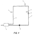
- the tempered medium for example hot water
- present in a container (1) is under delivery pressure.
- a line (2) has Tapping points (3, 4, 5).
- a circulation control valve (6) is arranged behind the last extraction point (5).
- a return line (7) leads from the circulation control valve (6) to a feed pump (9) and from there to the container (1).
- valve 3 has a temperature-sensitive element (10), which has thermal contact with the medium (11), for example water, which is located inside the housing (12) of the circulation control valve (6) and its normal flow direction is indicated by arrows bearing no reference numerals in FIGS. 3 and 4.
- the inlet opening is denoted by (13) and the outlet opening by (14).
- valve cover (18) rests on the valve seat (17) in the form of a disk.
- the valve cover (18) can be moved in the direction of the axis (16) between four wings that are evenly distributed over the circumference. 3 and 4, only two of the opposite wings (19) and (20) are visible.
- a ring (22) fixed to the housing serves as an abutment for one of the two bimetal disks (23, 24) from which the temperature-sensitive element (10) is made.
- the bimetallic disks are convexly pre-bent according to FIG. 4 and lie against one another with their edges. When heated, they jump into the concave deflection, which Fig. 3 shows.
- Fig. 3 shows that the bimental disks (23, 24) which have jumped into the concave deflection lie against one another with their curvatures and press the valve cover (18) away from the ring (22) with their edges and on the Bring the valve seat (17) into contact.
- the flow through the circulation control valve (6) under the influence of the return flow force caused by the feed pump (9) is not possible in this state of the circulation control valve (6).
- Fig. 4 and Fig. 10 illustrate that the circulation control valve (6) also prevents the medium from flowing back.
- the valve cover (18) would immediately lay against the valve seat (17) if the direction of flow should be reversed. He would do this regardless of the position of the bimetallic discs (23) and (24).
- the media circuit according to FIG. 2 differs from that of FIG. 1 by the following:
- a return line (7 ⁇ ) goes from the circulation control valve (6 ⁇ ).
- the two return lines (7) and (7 ⁇ ) open into the return line (7 ⁇ ), in the course of which the feed pump (9) is arranged.
- the line (2) has two further tapping points (28) and (29).
- a check valve (30) is arranged in the return line (7) between the feed pump (9) and the container (1).
- the last removal point (29) is assigned a structural unit (31) comprising a circulation control valve (32) and a pressure-loaded valve (33), which is described in more detail with reference to FIGS. 7 to 9.
- circulation control valve (32) and pressure-loaded valve (33) are assembled to form a structural unit (31).
- the inlet opening for the medium (11) is designated by (35), the outlet opening by (36).
- a valve seat (39) of the pressure-loaded valve (33) fixed to the housing is arranged concentrically to the central axis (38) of the housing (34) in the direction of flow of the medium (11), indicated by arrows not provided with reference numbers.
- valve seat (39) is followed by the centrally perforated sealing body (40), which carries the sealing ring (70) for the pressure-loaded valve (33) and is movable along the central axis (38).
- the sealing body (40) also carries the sealing ring (71) for the circulation control valve (32).
- the sealing body (40) also represents the bottom of a flowable cage (43).
- the cage (43) serves to axially guide a valve cover (18) of the circulation control valve (32) which can be moved in the direction of the central axis (38) and to accommodate the temperature-sensitive element (10) of the circulation control valve (32).
- the temperature-sensitive element (10) consists of the bimetallic disks (23) and (24) already known from FIGS. 3 and 4.
- the bottom (73) of the cage (72) serves on the one hand as an abutment for the temperature-sensitive element (10) and on the other hand as an abutment for the spring element (42).
- the force of the spring element (42) is applied to the sealing ring (via the bottom (73) of the cage (72) and via the four wings, of which only two wings (19) and (20) are visible in FIGS. 70) for the pressure-loaded valve (33) and thus to the valve seat (39).
- the cage (72) has four wings distributed evenly around the circumference, of which in 7 to 9 the wings (48, 49) and (50) are visible.
- the recesses between the wings allow the medium (11) to flow around the bimetallic discs (23) and (24).
- the cover (37) which closes the housing (34) is the second abutment for the spring element (42).
- the line (2) has only the tapping points (3, 4) and (29). From the line (2) branches off a line (2 ⁇ ) which has tapping points (3 ⁇ , 4 ⁇ ) and (29 ⁇ ). Upstream of the last extraction point (29 ⁇ ) there is a structural unit (31 ⁇ ) comprising a circulation control valve and a pressure-loaded valve, which is designed as described in FIGS. 7 to 9. Behind the last extraction point (29,) begins a return line (7 ⁇ ), which combines with the return line (7) to form a return line (7 ⁇ ). The feed pump (9) is in the train of the return line (7 ⁇ ). The return lines (7, 7 ⁇ ) are provided with check valves (54, 55).
- a timer (61) is fastened on the circulation control valve (6) via a holding bracket (60).
- This can consist, for example, of a synchronous motor which circulates a magnet (62), which is fastened on a disk (63), in a twenty-four hour cycle.
- the magnetic forces of the magnet (62) act on a magnet (64) which is firmly connected to a plunger (65).
- This acts via the temperature-sensitive element (10) on the valve cover (18) and urges it against the valve seat (17).
- the circulation control valve (6) is thus closed, although the temperature-sensitive element with its cooled bimetallic discs (23, 24) would in itself release the flow for the medium (11).
- the temperature-sensitive element (10) again determines the circulation in the media circuit.
- the return lines which generally have a smaller cross-section, are better protected against erosion damage and contamination or deposits due to the lower temperature level and the lower throughput.
- the circulation control valve is arranged behind the last extraction point, it is also relatively well protected against contamination, deposits and erosion damage. In addition, it can prevent backflow at this installation location, so that when opening the medium can not flow to a tapping point via the return lines of the tapping point. Regardless of the position of the circulation control valve, for example the valve cover (18) would lie on the valve seat (17) and prevent the backflow (FIG. 10).
- the circulating volume flowing through the return line and the resulting heat losses are so small that it makes sense, for example, in a domestic water system in a tenement building as a result of the invention, to incorporate quantity meters in branched line systems in the feeds for the purpose of hot water cost calculations without the line branches , which have the lower flow resistance as a whole, are impermissibly disadvantaged.
- the invention also enables the automatic tuning of branched circuits when only one pump is installed in the common part of the return line.
Landscapes
- Engineering & Computer Science (AREA)
- Physics & Mathematics (AREA)
- Thermal Sciences (AREA)
- Chemical & Material Sciences (AREA)
- Combustion & Propulsion (AREA)
- Mechanical Engineering (AREA)
- General Engineering & Computer Science (AREA)
- Temperature-Responsive Valves (AREA)
Applications Claiming Priority (2)
| Application Number | Priority Date | Filing Date | Title |
|---|---|---|---|
| DE3619217 | 1986-06-07 | ||
| DE19863619217 DE3619217A1 (de) | 1986-06-07 | 1986-06-07 | Vorrichtung zur regelung der zirkulation in einem temperaturbeaufschlagten, entnahmestellen aufweisenden medienkreislauf |
Publications (3)
| Publication Number | Publication Date |
|---|---|
| EP0249070A2 EP0249070A2 (de) | 1987-12-16 |
| EP0249070A3 EP0249070A3 (en) | 1988-07-20 |
| EP0249070B1 true EP0249070B1 (de) | 1991-04-17 |
Family
ID=6302525
Family Applications (1)
| Application Number | Title | Priority Date | Filing Date |
|---|---|---|---|
| EP87107376A Expired - Lifetime EP0249070B1 (de) | 1986-06-07 | 1987-05-21 | Vorrichtung zur Regelung der Zirkulation in einem temperaturbeaufschlagten, Entnahmestellen aufweisenden Medienkreislauf |
Country Status (3)
| Country | Link |
|---|---|
| EP (1) | EP0249070B1 (da) |
| DE (2) | DE3619217A1 (da) |
| DK (1) | DK291387A (da) |
Families Citing this family (10)
| Publication number | Priority date | Publication date | Assignee | Title |
|---|---|---|---|---|
| EP0690269B1 (en) * | 1994-06-29 | 1999-10-27 | Noboru Maruyama | Hot water supplying apparatus |
| DE19518910C1 (de) * | 1995-05-28 | 1996-09-05 | Richard Hettich | Warmwasserversorgung |
| DE19608325A1 (de) * | 1996-03-05 | 1997-09-18 | Oliver Kudera | Verfahren und Vorrichtung zum Ablassen und wieder Bereitstellen von kaltgewordenem Warmwasser aus der Warmwasserleitung durch die Kaltwasserleitung |
| DE10016179C2 (de) * | 2000-03-31 | 2002-10-24 | Bosch Gmbh Robert | Heizungsanlage mit einem Wärmeerzeuger, einem Wärmeübertrager für einen Heizkreis und einen Brauchwasserladekreis eines Warmwasserspeichers |
| DE10318821B4 (de) | 2003-04-16 | 2007-06-21 | Oliver Laing | Verfahren zur Bereitstellung von warmem Wasser in einer Brauchwasserinstallation und Brauchwasserinstallation |
| ATE556274T1 (de) * | 2005-01-13 | 2012-05-15 | Fischer Georg Jrg Ag | Verfahren und vorrichtung zur zirkulationsregelung in warmwasserkreisläufen |
| US9027844B2 (en) | 2010-03-05 | 2015-05-12 | Xylem Ip Holdings Llc | Water delivery system and valve for a sink |
| DE202010003376U1 (de) * | 2010-03-09 | 2011-08-01 | Gebrüder Kemper GmbH + Co Metallwerke | Trink- und Brauchwassersystem |
| US8934763B2 (en) | 2012-04-20 | 2015-01-13 | Xylem Ip Holdings Llc | Water delivery system and method for making hot water available in a domestic hot water installation |
| CZ20238A3 (cs) * | 2023-01-11 | 2024-03-27 | Pavel Koudelka | Oběžná soustava pro ohřev užitkové vody |
Family Cites Families (6)
| Publication number | Priority date | Publication date | Assignee | Title |
|---|---|---|---|---|
| DE2945568A1 (de) * | 1979-11-10 | 1981-05-21 | Wolfgang Dipl.-Phys. Dr.rer.nat. 5100 Aachen Thiele | Warmwasserversorgungsvorrichtung |
| DE3143081A1 (de) * | 1981-10-30 | 1983-05-11 | Grundfos A/S, 8850 Bjerringbro | Brauchwasseranlage mit gesteuertem umwaelzpumpenaggregat |
| DE3309199A1 (de) * | 1982-09-07 | 1984-09-20 | Karl Heinz 8909 Haupeltshofen Goßner | Brauchwasser-zirkulationsanordnung fuer warmwasser |
| DE3242491C2 (de) * | 1982-11-18 | 1987-04-09 | Diehl GmbH & Co, 8500 Nürnberg | Häusliches Warmwasserversorgungssystem |
| US4554688A (en) * | 1984-04-17 | 1985-11-26 | Puccerella Thomas J | Water saving system |
| DE3431555A1 (de) * | 1984-08-28 | 1986-03-06 | Peter von 6300 Gießen Schnakenburg | Warmwasser-versorgungsanlage |
-
1986
- 1986-06-07 DE DE19863619217 patent/DE3619217A1/de not_active Withdrawn
-
1987
- 1987-05-21 EP EP87107376A patent/EP0249070B1/de not_active Expired - Lifetime
- 1987-05-21 DE DE8787107376T patent/DE3769371D1/de not_active Expired - Lifetime
- 1987-06-04 DK DK291387A patent/DK291387A/da not_active Application Discontinuation
Also Published As
| Publication number | Publication date |
|---|---|
| DE3619217A1 (de) | 1987-12-10 |
| DK291387D0 (da) | 1987-06-04 |
| DE3769371D1 (de) | 1991-05-23 |
| DK291387A (da) | 1987-12-08 |
| EP0249070A3 (en) | 1988-07-20 |
| EP0249070A2 (de) | 1987-12-16 |
Similar Documents
| Publication | Publication Date | Title |
|---|---|---|
| EP2487301B1 (de) | Trink- oder Brauchwassersystem | |
| EP0249070B1 (de) | Vorrichtung zur Regelung der Zirkulation in einem temperaturbeaufschlagten, Entnahmestellen aufweisenden Medienkreislauf | |
| DE3522344A1 (de) | Verfahren zur regelung der temperatur des an ein warmwasser-versorgungssystem mit zirkulationsleitung angeschlossenen verbrauchern zufliessenden warmwassers und warmwasserversorgungssystem zur durchfuehrung des verfahrens | |
| DE102012211921B4 (de) | Temperaturabhängig schaltendes Ventil und Temperatur-Schichtungssystem zum Speichern von Flüssigkeiten unterschiedlicher Temperatur | |
| DE19504730C1 (de) | Warmwasserbereitungsanlage nach dem Durchflußprinzip mit Leistungsbegrenzung | |
| DE3843376C2 (da) | ||
| DE1299393B (de) | Warmwassererzeuger, insbesondere Heizwassererzeuger | |
| DE1903774A1 (de) | Vorrichtung zum Erhitzen fluessiger Medien | |
| EP0981784B1 (de) | Wassersteuervorrichtung | |
| EP1792125B1 (de) | Brauchwasserbereiter | |
| DE4418737C2 (de) | Anordnung zur Warmwasserbereitung mit Satelitenspeicher und Rückschlagventil | |
| DE19607432C1 (de) | Vorrichtung zur Durchflußregelung einer Flüssigkeit | |
| DE19816037A1 (de) | Wasserspeicher in Heizungsanlagen, wie Warmwasser- oder Pufferspeicher | |
| CH655376A5 (de) | Heizanlage zur warmwasserbereitung. | |
| DE69421388T2 (de) | Warmwasserversorgungsgerät | |
| DE1454513C (da) | ||
| DE2930276A1 (de) | Thermostatisch geregeltes mischventil | |
| EP0332606B1 (de) | Vorrichtung zur Erwärmung von Brauchwasser | |
| DE310254C (de) | Aus einem Stromerhitzer und einem Vorratserhitzer bestehender Warmwasserbereitungsanlage mit Gasbeheizung | |
| DE69614926T2 (de) | Heizung für Warmwasserspeicher | |
| AT294986B (de) | Elektrischer Durchlauferhitzer | |
| DE29819670U1 (de) | Wärmeaustauscher-Aggregat für die Brauchwasserbereitung | |
| DE1944439U (de) | Heizzelle. | |
| AT139956B (de) | Gliederkessel mit Vorrichtung zur Herbeiführung unterschiedlicher Temperaturen in den Kesselteilen. | |
| DE102011013807B4 (de) | Ventil für flüssige Medien, insbesondere für den Einsatz in Heizungs- und/oder Photothermikanlagen |
Legal Events
| Date | Code | Title | Description |
|---|---|---|---|
| PUAI | Public reference made under article 153(3) epc to a published international application that has entered the european phase |
Free format text: ORIGINAL CODE: 0009012 |
|
| AK | Designated contracting states |
Kind code of ref document: A2 Designated state(s): BE CH DE FR IT LI NL SE |
|
| RHK1 | Main classification (correction) |
Ipc: F24D 17/00 |
|
| PUAL | Search report despatched |
Free format text: ORIGINAL CODE: 0009013 |
|
| AK | Designated contracting states |
Kind code of ref document: A3 Designated state(s): BE CH DE FR IT LI NL SE |
|
| 17P | Request for examination filed |
Effective date: 19881124 |
|
| 17Q | First examination report despatched |
Effective date: 19900219 |
|
| GRAA | (expected) grant |
Free format text: ORIGINAL CODE: 0009210 |
|
| AK | Designated contracting states |
Kind code of ref document: B1 Designated state(s): BE CH DE FR IT LI NL SE |
|
| PG25 | Lapsed in a contracting state [announced via postgrant information from national office to epo] |
Ref country code: IT Free format text: LAPSE BECAUSE OF FAILURE TO SUBMIT A TRANSLATION OF THE DESCRIPTION OR TO PAY THE FEE WITHIN THE PRE;WARNING: LAPSES OF ITALIAN PATENTS WITH EFFECTIVE DATE BEFORE 2007 MAY HAVE OCCURRED AT ANY TIME BEFORE 2007. THE CORRECT EFFECTIVE DATE MAY BE DIFFERENT FROM THE ONE RECORDED.SCRIBED TIME-LIMIT Effective date: 19910417 Ref country code: NL Effective date: 19910417 |
|
| REF | Corresponds to: |
Ref document number: 3769371 Country of ref document: DE Date of ref document: 19910523 |
|
| ET | Fr: translation filed | ||
| NLV1 | Nl: lapsed or annulled due to failure to fulfill the requirements of art. 29p and 29m of the patents act | ||
| PLBE | No opposition filed within time limit |
Free format text: ORIGINAL CODE: 0009261 |
|
| STAA | Information on the status of an ep patent application or granted ep patent |
Free format text: STATUS: NO OPPOSITION FILED WITHIN TIME LIMIT |
|
| 26N | No opposition filed | ||
| PGFP | Annual fee paid to national office [announced via postgrant information from national office to epo] |
Ref country code: SE Payment date: 19920427 Year of fee payment: 6 |
|
| PGFP | Annual fee paid to national office [announced via postgrant information from national office to epo] |
Ref country code: BE Payment date: 19920514 Year of fee payment: 6 |
|
| PGFP | Annual fee paid to national office [announced via postgrant information from national office to epo] |
Ref country code: FR Payment date: 19920515 Year of fee payment: 6 |
|
| PGFP | Annual fee paid to national office [announced via postgrant information from national office to epo] |
Ref country code: CH Payment date: 19920526 Year of fee payment: 6 |
|
| PGFP | Annual fee paid to national office [announced via postgrant information from national office to epo] |
Ref country code: DE Payment date: 19920602 Year of fee payment: 6 |
|
| PG25 | Lapsed in a contracting state [announced via postgrant information from national office to epo] |
Ref country code: SE Effective date: 19930522 |
|
| PG25 | Lapsed in a contracting state [announced via postgrant information from national office to epo] |
Ref country code: BE Effective date: 19930531 Ref country code: LI Effective date: 19930531 Ref country code: CH Effective date: 19930531 |
|
| BERE | Be: lapsed |
Owner name: DEUTSCHE VORTEX G.M.B.H. Effective date: 19930531 |
|
| PG25 | Lapsed in a contracting state [announced via postgrant information from national office to epo] |
Ref country code: FR Effective date: 19940131 |
|
| REG | Reference to a national code |
Ref country code: CH Ref legal event code: PL |
|
| PG25 | Lapsed in a contracting state [announced via postgrant information from national office to epo] |
Ref country code: DE Effective date: 19940201 |
|
| REG | Reference to a national code |
Ref country code: FR Ref legal event code: ST |
|
| EUG | Se: european patent has lapsed |
Ref document number: 87107376.3 Effective date: 19931210 |