EP0249110A2 - Sonde pour un détecteur de métal - Google Patents
Sonde pour un détecteur de métal Download PDFInfo
- Publication number
- EP0249110A2 EP0249110A2 EP87107842A EP87107842A EP0249110A2 EP 0249110 A2 EP0249110 A2 EP 0249110A2 EP 87107842 A EP87107842 A EP 87107842A EP 87107842 A EP87107842 A EP 87107842A EP 0249110 A2 EP0249110 A2 EP 0249110A2
- Authority
- EP
- European Patent Office
- Prior art keywords
- housing
- coils
- probe according
- probe
- web
- Prior art date
- Legal status (The legal status is an assumption and is not a legal conclusion. Google has not performed a legal analysis and makes no representation as to the accuracy of the status listed.)
- Granted
Links
Images


Classifications
-
- G—PHYSICS
- G01—MEASURING; TESTING
- G01V—GEOPHYSICS; GRAVITATIONAL MEASUREMENTS; DETECTING MASSES OR OBJECTS; TAGS
- G01V3/00—Electric or magnetic prospecting or detecting; Measuring magnetic field characteristics of the earth, e.g. declination, deviation
- G01V3/08—Electric or magnetic prospecting or detecting; Measuring magnetic field characteristics of the earth, e.g. declination, deviation operating with magnetic or electric fields produced or modified by objects or geological structures or by detecting devices
- G01V3/10—Electric or magnetic prospecting or detecting; Measuring magnetic field characteristics of the earth, e.g. declination, deviation operating with magnetic or electric fields produced or modified by objects or geological structures or by detecting devices using induction coils
- G01V3/104—Electric or magnetic prospecting or detecting; Measuring magnetic field characteristics of the earth, e.g. declination, deviation operating with magnetic or electric fields produced or modified by objects or geological structures or by detecting devices using induction coils using several coupled or uncoupled coils
- G01V3/105—Electric or magnetic prospecting or detecting; Measuring magnetic field characteristics of the earth, e.g. declination, deviation operating with magnetic or electric fields produced or modified by objects or geological structures or by detecting devices using induction coils using several coupled or uncoupled coils forming directly coupled primary and secondary coils or loops
- G01V3/107—Electric or magnetic prospecting or detecting; Measuring magnetic field characteristics of the earth, e.g. declination, deviation operating with magnetic or electric fields produced or modified by objects or geological structures or by detecting devices using induction coils using several coupled or uncoupled coils forming directly coupled primary and secondary coils or loops using compensating coil or loop arrangements
Definitions
- the invention relates to a probe for a metal detector with a plate-shaped housing, with a transmitter coil arranged therein and with at least two receiver coils arranged therein, electrically connected to one another and lying essentially in the same plane as the transmitter coil.
- Metal detectors with which the ground or other non-metallic media are examined, essentially consist of a plate-shaped or ring-shaped probe, which receives one or more search coils, and device electronics with power supply, which generates acoustic or optical display signals when metal appears.
- the search coil consists of transmitter and receiver coils. These can also be combined into a coil.
- the mode of operation of such devices is that an electromagnetic alternating field or short pulses are emitted by the probe, which induce eddy currents in the metal search objects. These eddy currents create a secondary focus, which acts back on the probe as a magnetic echo or location signal.
- the probe can contain one or more search coils that perform various functions.
- Simple metal detectors are known as relative knives educated. They only show the relative change in conductivity of the examined medium. Their main disadvantage is that the medium to be searched, such as heavily mineralized soil, magnetic road surfaces or salt water, can trigger significant interference signals.
- So-called differential meters help here. Soil magnetic effects, disturbing conductivity as well as alternating field influences can be masked out within wide limits by a difference measurement, which takes place in the probe.
- the principle is that the receiver coils lying in the field of action of a transmitter coil are electrically connected to one another and are arranged symmetrically in space in relation to the search coil. This decouples processes on the transmitter and receiver side.
- the electrical difference between the receiver coils is zero. There is no interference signal.
- the effect of disturbing alternating fields, such as those emanating from high-voltage power lines, is also eliminated in the receiver coils connected in opposite directions.
- This embodiment has a large area and a high Ge important.
- a probe built in this way is not only unwieldy, but is also exposed to thermal influences due to the large surface area. This causes electrical instabilities.
- One tries to counter this disadvantage by means of pocket-like coverings made of heat-insulating material.
- the manufacture of such a probe is relatively complex, cumbersome and therefore also expensive.
- the probe designed in this way not only has weight disadvantages, high water resistance when searching quickly, such as in shallow pools, but also low localization accuracy when locating with the edge of the probe (searching with a vertically tilted probe).
- the present invention has set itself the task of eliminating these disadvantages of a differential meter and of creating an arrangement which is light and easy to handle, accurate in location and less expensive to manufacture.
- the solution to this problem results according to the invention in a surprisingly simple manner in that the receiver coils are located within the transmitter coil.
- the volume of the housing predetermined by the size of the transmitter coil is not increased and is optimally utilized.
- neither the cross section nor the height of the housing are increased. This keeps the weight and surface area of the housing low. The housing and thus the coils are only slightly warmed up by the sun.
- the water resistance already mentioned also remains low. The localization sharpness is increased.
- the housing is expediently divided into several sections by at least one web and the receiver coils are arranged in these.
- the web can run symmetrically through the center of the housing or can also pass through it at a distance from and parallel to the center line of the housing.
- the receiver coils have different sizes and receive different inductances. This can be electrically balanced.
- the housing is divided into two sections by a web. This means that two receiver coils are arranged in one transmitter coil.
- the housing can also be divided into four sections by two webs intersecting at 90 ° or in three sections by three webs intersecting at 120 °. In these cases, four or three receiver coils are arranged within a transmitter coil.
- the crosspiece or the crosspieces advantageously have a U profile in cross section, the crosspiece of the U profile resting on the bottom of the housing or being formed integrally therewith, while the flanges stand up and the coils are placed around the flanges.
- a web runs along the circumference of the housing, while the flanges of the web or webs running through the housing merge into the inner flange of the web running along the circumference, and the coils are inserted into the troughs enclosed by the flanges of all webs. As a result, the individual windings of the coils are held securely.
- the housing has a circular shape. However, it can also have a square shape or any other shape.
- the receiver coils are inside the transmitter coil.
- the external coil can also be switched as a receiver coil and the internal coils can be switched as a transmitter coil.
- the main advantage of the invention lies not only in the simple manufacture, but also in the tight coupling of the coils, as a result of which a high detection sensitivity is achieved.
- a sharp localization of small metal objects with the probe edge is easily possible.
- the probe designed in this way is light in weight and has little movement resistance when searching underwater. Due to the small surface, the thermal impact is only slight. Due to the symmetrical structure of the probe and coils, high electrical stability is achieved even with different temperatures.
- the manufacture of different types of housings is simple, since the plastic injection mold can be designed to be interchangeable for the different webs.
- the housing can be divided into three circular sector-shaped sections by three webs and a receiver coil can be arranged in each section.
- One of these coils can also be switched as a transmitter coil, with the other two coils being switched against one another for differential measurement and zero compensation.
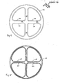
- Fig. 1 shows the housing 12 of the known differential meter.
- the transmitter coil 14 is located in the housing 12.
- Four receiver coils 16, 18, 20 and 22 lie above the transmitter coil 14. They lie in recesses or depressions in the housing cover.
- FIG. 2 shows the housing 12 of a probe designed according to the invention.
- a web with upstanding flanges 24 runs along the center line through the housing 12.
- Another web with upstanding flanges 24 runs along and parallel to the circumference of the housing.
- the flanges 24 merge and include troughs 26.
- the transmitter coil 14 lies in the trough 26 running on the circumference of the housing.
- the two receiver coils 16 and 18 lie in the other two D-shaped troughs 26. In this way, they themselves also have a D-shape.
- two webs with flanges 24 intersecting at 90 ° run through the housing.
- a further web with flanges 24 runs along and parallel to the circumference of the housing.
- the upstanding flanges 24 of these webs merge. This results in four circular sector-shaped troughs 26.
- the transmitter coil is located 14 in the trough 26 running on the circumference of the housing.
- the four receiver coils 16, 18, 20 and 22 lie in the four troughs 26 in the shape of a circular sector.
- FIGS. 6 and 7 show the same picture for a housing 12 which is divided into three sections by three webs.
- three receiver coils 16, 18, 20 can lie in a transmitter coil 14.
- the transmitter coil 14 wound in a circular shape can be omitted.
- One of the coils lying in a circular sector is then switched as a transmitter coil.
- the coils are cast in the housing with synthetic resin.
Landscapes
- Life Sciences & Earth Sciences (AREA)
- Engineering & Computer Science (AREA)
- Physics & Mathematics (AREA)
- Remote Sensing (AREA)
- General Physics & Mathematics (AREA)
- Environmental & Geological Engineering (AREA)
- Geology (AREA)
- General Life Sciences & Earth Sciences (AREA)
- Electromagnetism (AREA)
- Geophysics (AREA)
- Geophysics And Detection Of Objects (AREA)
- Investigating Or Analyzing Materials By The Use Of Magnetic Means (AREA)
- Analysing Materials By The Use Of Radiation (AREA)
- Arrangements For Transmission Of Measured Signals (AREA)
- Fire-Detection Mechanisms (AREA)
- Cephalosporin Compounds (AREA)
Priority Applications (1)
| Application Number | Priority Date | Filing Date | Title |
|---|---|---|---|
| AT87107842T ATE63172T1 (de) | 1986-06-07 | 1987-05-29 | Sonde fuer ein metallsuchgeraet. |
Applications Claiming Priority (2)
| Application Number | Priority Date | Filing Date | Title |
|---|---|---|---|
| DE3619308A DE3619308C1 (de) | 1986-06-07 | 1986-06-07 | Sonde fuer ein Metallsuchgeraet |
| DE3619308 | 1986-06-07 |
Publications (3)
| Publication Number | Publication Date |
|---|---|
| EP0249110A2 true EP0249110A2 (fr) | 1987-12-16 |
| EP0249110A3 EP0249110A3 (en) | 1988-10-19 |
| EP0249110B1 EP0249110B1 (fr) | 1991-05-02 |
Family
ID=6302585
Family Applications (1)
| Application Number | Title | Priority Date | Filing Date |
|---|---|---|---|
| EP87107842A Expired - Lifetime EP0249110B1 (fr) | 1986-06-07 | 1987-05-29 | Sonde pour un détecteur de métal |
Country Status (4)
| Country | Link |
|---|---|
| EP (1) | EP0249110B1 (fr) |
| AT (1) | ATE63172T1 (fr) |
| DE (2) | DE3619308C1 (fr) |
| ES (1) | ES2022201B3 (fr) |
Cited By (10)
| Publication number | Priority date | Publication date | Assignee | Title |
|---|---|---|---|---|
| EP0393387A3 (fr) * | 1989-04-19 | 1992-07-08 | INSTITUT DR. FRIEDRICH FÖRSTER PRÜFGERÄTEBAU GMBH & CO. KG | Agencement de bobines pour un appareil de détection inductive |
| DE4423661A1 (de) * | 1994-07-06 | 1996-01-11 | Foerster Inst Dr Friedrich | Suchspulenanordnung |
| WO1996001436A1 (fr) * | 1994-07-06 | 1996-01-18 | Dornier Gmbh | Procede et systeme de detection d'objets dangereux abandonnes |
| WO1996011414A1 (fr) * | 1994-10-10 | 1996-04-18 | Dornier Gmbh | Systeme de detection pour detecter, localiser et identifier des objets metalliques |
| EP0764856A3 (fr) * | 1995-09-21 | 1998-12-16 | Firma Ing. Klaus Ebinger | Capteur pour un détecteur de métal |
| EP0837344A3 (fr) * | 1996-10-16 | 2000-12-20 | Firma Ing. Klaus Ebinger | Procédé et dispositif pour détecter d'objets métalliques |
| WO2003034095A1 (fr) * | 2001-10-17 | 2003-04-24 | Qinetiq Limited | Appareil de detection de metaux |
| USD531919S1 (en) | 2004-12-16 | 2006-11-14 | Company Ing. Klaus Ebinger | Search probe |
| EP2224267A3 (fr) * | 2009-02-27 | 2016-12-07 | HILTI Aktiengesellschaft | Procédé de fonctionnement et agencement de bobines pour un capteur magnétique destiné à la détection d'objets métalliques dans un sous-sol |
| USD859191S1 (en) | 2016-06-24 | 2019-09-10 | Stanley Black & Decker Inc. | Hidden object detector |
Families Citing this family (16)
| Publication number | Priority date | Publication date | Assignee | Title |
|---|---|---|---|---|
| DE3733529A1 (de) * | 1987-10-03 | 1989-04-20 | Foerster Inst Dr Friedrich | Induktives metallteilesuchgeraet |
| DE9300788U1 (de) * | 1993-01-21 | 1993-05-27 | Ebinger, Klaus, 5000 Köln | Ringförmige Sonde für ein Metallsuchgerät |
| DE29508963U1 (de) * | 1995-05-31 | 1995-08-17 | Maier, Hans-Jürgen, 72072 Tübingen | Vorrichtung zur Erkennung von Metallteilen |
| DE60130890T2 (de) * | 2001-09-26 | 2008-08-14 | Hilti Ag | Induktive Sensoranordnung und Verfahren zur Erfassung von eisernen Objekten |
| WO2010133501A1 (fr) | 2009-05-18 | 2010-11-25 | Sick Ag | Capteur destiné à détecter des objets métalliques |
| DE102009021804A1 (de) | 2009-05-18 | 2010-11-25 | Gerd Reime | Metalldetektor |
| DE202010000932U1 (de) | 2009-12-30 | 2010-04-01 | Ebinger, Klaus | Detektorsonde |
| DE102010004584A1 (de) | 2009-12-30 | 2011-07-07 | Ebinger, Klaus, 51149 | Detektorsonde |
| DE102011000302B4 (de) * | 2011-01-25 | 2015-04-02 | Sartorius Industrial Scales Gmbh & Co. Kg | Metalldetektor |
| DE102012001202A1 (de) | 2011-08-10 | 2013-02-14 | Gerd Reime | Sensor zur Ortung metallischer Objekte sowie zugehörige Spule |
| GB2508923A (en) | 2012-12-17 | 2014-06-18 | Bombardier Transp Gmbh | Inductive power transfer system having inductive sensing array |
| CN105842743A (zh) * | 2016-03-25 | 2016-08-10 | 东莞市华盾电子科技有限公司 | 一种探测器及其生产方法 |
| CN105702442A (zh) * | 2016-03-25 | 2016-06-22 | 东莞市华盾电子科技有限公司 | 用于探测器的线圈结构及其构成的通过式探测器 |
| CN105700023A (zh) * | 2016-03-25 | 2016-06-22 | 东莞市华盾电子科技有限公司 | 一种手持式金属探测器 |
| US20220291412A1 (en) * | 2021-03-12 | 2022-09-15 | Christopher Frank Eckman | Metal detecting sensor array for discriminating between different objects |
| DE102024110381A1 (de) * | 2024-04-12 | 2025-10-16 | Endress+Hauser SE+Co. KG | Metalldetektor zur Positionsbestimmung von leitfähigen Gegenständen, Verfahren zur Positionsbestimmung von leitfähigen Gegenständen mit einem Metalldetektor, Messstelle zum Entdecken von leitfähigen Gegenständen in einem Medium |
Family Cites Families (4)
| Publication number | Priority date | Publication date | Assignee | Title |
|---|---|---|---|---|
| FR960966A (fr) * | 1950-04-28 | |||
| FR1493026A (fr) * | 1966-07-12 | 1967-08-25 | Materiel Electromagnetique S I | Perfectionnements aux détecteurs de métaux |
| US3882374A (en) * | 1974-04-18 | 1975-05-06 | Us Army | Transmitting-receiving coil configuration |
| EP0130940B2 (fr) * | 1983-07-05 | 1993-12-01 | C.A. Weidmüller GmbH & Co. | Dispositif inductif sensoriel et dispositif de mesure pour son utilisation |
-
1986
- 1986-06-07 DE DE3619308A patent/DE3619308C1/de not_active Expired - Lifetime
-
1987
- 1987-05-29 EP EP87107842A patent/EP0249110B1/fr not_active Expired - Lifetime
- 1987-05-29 AT AT87107842T patent/ATE63172T1/de not_active IP Right Cessation
- 1987-05-29 ES ES87107842T patent/ES2022201B3/es not_active Expired - Lifetime
- 1987-05-29 DE DE8787107842T patent/DE3769702D1/de not_active Expired - Lifetime
Cited By (14)
| Publication number | Priority date | Publication date | Assignee | Title |
|---|---|---|---|---|
| EP0393387A3 (fr) * | 1989-04-19 | 1992-07-08 | INSTITUT DR. FRIEDRICH FÖRSTER PRÜFGERÄTEBAU GMBH & CO. KG | Agencement de bobines pour un appareil de détection inductive |
| DE4423661A1 (de) * | 1994-07-06 | 1996-01-11 | Foerster Inst Dr Friedrich | Suchspulenanordnung |
| WO1996001436A1 (fr) * | 1994-07-06 | 1996-01-18 | Dornier Gmbh | Procede et systeme de detection d'objets dangereux abandonnes |
| US5719500A (en) * | 1994-07-06 | 1998-02-17 | Dornier Gmbh | Process for detecting metallic items including a search path defined by a linear movement with a superimposed rotational movement along a curved closed path |
| WO1996011414A1 (fr) * | 1994-10-10 | 1996-04-18 | Dornier Gmbh | Systeme de detection pour detecter, localiser et identifier des objets metalliques |
| EP0764856A3 (fr) * | 1995-09-21 | 1998-12-16 | Firma Ing. Klaus Ebinger | Capteur pour un détecteur de métal |
| EP0837344A3 (fr) * | 1996-10-16 | 2000-12-20 | Firma Ing. Klaus Ebinger | Procédé et dispositif pour détecter d'objets métalliques |
| WO2003034095A1 (fr) * | 2001-10-17 | 2003-04-24 | Qinetiq Limited | Appareil de detection de metaux |
| US7414404B2 (en) | 2001-10-17 | 2008-08-19 | Qinetiq Limited | Metal detection apparatus |
| USD531919S1 (en) | 2004-12-16 | 2006-11-14 | Company Ing. Klaus Ebinger | Search probe |
| EP2224267A3 (fr) * | 2009-02-27 | 2016-12-07 | HILTI Aktiengesellschaft | Procédé de fonctionnement et agencement de bobines pour un capteur magnétique destiné à la détection d'objets métalliques dans un sous-sol |
| US9651702B2 (en) | 2009-02-27 | 2017-05-16 | Hilti Aktiengesellschaft | Operating method and coil arrangement for a magnetic sensor for detecting metallic objects in a subgrade |
| USD859191S1 (en) | 2016-06-24 | 2019-09-10 | Stanley Black & Decker Inc. | Hidden object detector |
| US10571423B2 (en) | 2016-06-24 | 2020-02-25 | Stanley Black & Decker Inc. | Systems and methods for locating a stud |
Also Published As
| Publication number | Publication date |
|---|---|
| EP0249110B1 (fr) | 1991-05-02 |
| DE3769702D1 (de) | 1991-06-06 |
| EP0249110A3 (en) | 1988-10-19 |
| ATE63172T1 (de) | 1991-05-15 |
| ES2022201B3 (es) | 1991-12-01 |
| DE3619308C1 (de) | 1991-08-29 |
Similar Documents
| Publication | Publication Date | Title |
|---|---|---|
| DE3619308C1 (de) | Sonde fuer ein Metallsuchgeraet | |
| DE69707858T2 (de) | Füllstandsmesser mit magnetischem schwimmer | |
| DE4300529C2 (de) | Verfahren und Vorrichtung zur Bestimmung der räumlichen Anordnung eines richtungsempfindlichen Magnetfeldsensors | |
| DE4022739A1 (de) | Vorrichtung zur pruefung von mit magnetischen eigenschaften ausgestatteten messobjekten | |
| WO1996011414A1 (fr) | Systeme de detection pour detecter, localiser et identifier des objets metalliques | |
| DE3716985C1 (de) | Vorrichtung zur Erfassung von Staerke und Richtung eines Magnetfeldes,insbesondere des Erdmagnetfeldes | |
| DE10003253A1 (de) | Sondenortungseinrichtung | |
| DE2458928A1 (de) | Verfahren und vorrichtung zur messung von winkeln | |
| DE102012220468B3 (de) | Längenmessgerät | |
| DE4316344A1 (de) | Strömungsmeßeinrichtung | |
| WO1990010880A1 (fr) | Procede et dispositif de localisation de sous-marins | |
| DE3615652A1 (de) | Induktives suchgeraet | |
| DE8615489U1 (de) | Sonde für ein Metallsuchgerät | |
| DE1623577C2 (de) | Magnetometer mit direkter Zeitverschlüsselung | |
| EP0024307B1 (fr) | Dispositif pour la compensation du champ magnétique parasite d'un objet à l'aide d'une installation d'auto-protection magnétique | |
| DE2133725A1 (de) | Elektronischer muenzpruefer | |
| DE4306183C1 (de) | Gerät zur Bestimmung paramagnetischer Eigenschaften von Stoffen mit einer magnetischen Signalkompensationsvorrichtung | |
| DE2241095C3 (de) | Meßumformer für einen Druck- und Durchflußmengenmesser | |
| DE69031578T2 (de) | Anordnung zum Spurführen von gleisfreien Falzungen | |
| WO2006066529A2 (fr) | Dispositif et procede pour reperer des objets magnetiques ou magnetisables | |
| DE3118768A1 (de) | Vorrichtung zur erfassung der stellung oder des weges eines beweglichen bauteiles, insbesondere einer brennkraftmaschine | |
| EP0882953A1 (fr) | Accouplement magnétique pour compteur d'eau pourvu d'une protection contre les champs magnétiques extérieurs | |
| EP0096380A2 (fr) | Procédé de détection d'objets ferromagnétiques souterrains | |
| DE3235033A1 (de) | Induktiver messwertgeber zur umwandlung der linearen hubbewegungen eines fuehlers mechanischer messgeraete in elektrische messsignale | |
| DE1285191B (de) | Einrichtung zur beruehrungslosen induktiven Messung der axialen und/oder radialen Verschiebung rotierender Wellen |
Legal Events
| Date | Code | Title | Description |
|---|---|---|---|
| PUAI | Public reference made under article 153(3) epc to a published international application that has entered the european phase |
Free format text: ORIGINAL CODE: 0009012 |
|
| AK | Designated contracting states |
Kind code of ref document: A2 Designated state(s): AT BE CH DE ES FR GB GR IT LI LU NL SE |
|
| PUAL | Search report despatched |
Free format text: ORIGINAL CODE: 0009013 |
|
| AK | Designated contracting states |
Kind code of ref document: A3 Designated state(s): AT BE CH DE ES FR GB GR IT LI LU NL SE |
|
| 17P | Request for examination filed |
Effective date: 19890124 |
|
| 17Q | First examination report despatched |
Effective date: 19900508 |
|
| GRAA | (expected) grant |
Free format text: ORIGINAL CODE: 0009210 |
|
| AK | Designated contracting states |
Kind code of ref document: B1 Designated state(s): AT BE CH DE ES FR GB GR IT LI LU NL SE |
|
| PG25 | Lapsed in a contracting state [announced via postgrant information from national office to epo] |
Ref country code: NL Effective date: 19910502 Ref country code: GR Free format text: LAPSE BECAUSE OF FAILURE TO SUBMIT A TRANSLATION OF THE DESCRIPTION OR TO PAY THE FEE WITHIN THE PRESCRIBED TIME-LIMIT Effective date: 19910502 Ref country code: BE Effective date: 19910502 |
|
| REF | Corresponds to: |
Ref document number: 63172 Country of ref document: AT Date of ref document: 19910515 Kind code of ref document: T |
|
| ITF | It: translation for a ep patent filed | ||
| PG25 | Lapsed in a contracting state [announced via postgrant information from national office to epo] |
Ref country code: LU Free format text: LAPSE BECAUSE OF NON-PAYMENT OF DUE FEES Effective date: 19910531 Ref country code: LI Effective date: 19910531 Ref country code: CH Effective date: 19910531 |
|
| REF | Corresponds to: |
Ref document number: 3769702 Country of ref document: DE Date of ref document: 19910606 |
|
| GBT | Gb: translation of ep patent filed (gb section 77(6)(a)/1977) | ||
| PGFP | Annual fee paid to national office [announced via postgrant information from national office to epo] |
Ref country code: SE Payment date: 19910628 Year of fee payment: 5 |
|
| ET | Fr: translation filed | ||
| NLV1 | Nl: lapsed or annulled due to failure to fulfill the requirements of art. 29p and 29m of the patents act | ||
| REG | Reference to a national code |
Ref country code: CH Ref legal event code: PL |
|
| PLBE | No opposition filed within time limit |
Free format text: ORIGINAL CODE: 0009261 |
|
| STAA | Information on the status of an ep patent application or granted ep patent |
Free format text: STATUS: NO OPPOSITION FILED WITHIN TIME LIMIT |
|
| 26N | No opposition filed | ||
| PG25 | Lapsed in a contracting state [announced via postgrant information from national office to epo] |
Ref country code: SE Effective date: 19920530 |
|
| EUG | Se: european patent has lapsed |
Ref document number: 87107842.4 Effective date: 19921204 |
|
| PGFP | Annual fee paid to national office [announced via postgrant information from national office to epo] |
Ref country code: ES Payment date: 19950531 Year of fee payment: 9 |
|
| PG25 | Lapsed in a contracting state [announced via postgrant information from national office to epo] |
Ref country code: ES Free format text: LAPSE BECAUSE OF NON-PAYMENT OF DUE FEES Effective date: 19960530 |
|
| REG | Reference to a national code |
Ref country code: ES Ref legal event code: FD2A Effective date: 19990301 |
|
| PGFP | Annual fee paid to national office [announced via postgrant information from national office to epo] |
Ref country code: GB Payment date: 20000413 Year of fee payment: 14 |
|
| PGFP | Annual fee paid to national office [announced via postgrant information from national office to epo] |
Ref country code: FR Payment date: 20000530 Year of fee payment: 14 Ref country code: AT Payment date: 20000530 Year of fee payment: 14 |
|
| PG25 | Lapsed in a contracting state [announced via postgrant information from national office to epo] |
Ref country code: GB Free format text: LAPSE BECAUSE OF NON-PAYMENT OF DUE FEES Effective date: 20010529 Ref country code: AT Free format text: LAPSE BECAUSE OF NON-PAYMENT OF DUE FEES Effective date: 20010529 |
|
| GBPC | Gb: european patent ceased through non-payment of renewal fee |
Effective date: 20010529 |
|
| PG25 | Lapsed in a contracting state [announced via postgrant information from national office to epo] |
Ref country code: FR Free format text: LAPSE BECAUSE OF NON-PAYMENT OF DUE FEES Effective date: 20020131 |
|
| PG25 | Lapsed in a contracting state [announced via postgrant information from national office to epo] |
Ref country code: IT Free format text: LAPSE BECAUSE OF NON-PAYMENT OF DUE FEES Effective date: 20050529 |
|
| PGFP | Annual fee paid to national office [announced via postgrant information from national office to epo] |
Ref country code: DE Payment date: 20050530 Year of fee payment: 19 |
|
| PG25 | Lapsed in a contracting state [announced via postgrant information from national office to epo] |
Ref country code: DE Free format text: LAPSE BECAUSE OF NON-PAYMENT OF DUE FEES Effective date: 20061201 |