EP0249129A2 - Moteur à combustion interne du type à deux temps - Google Patents
Moteur à combustion interne du type à deux temps Download PDFInfo
- Publication number
- EP0249129A2 EP0249129A2 EP87107969A EP87107969A EP0249129A2 EP 0249129 A2 EP0249129 A2 EP 0249129A2 EP 87107969 A EP87107969 A EP 87107969A EP 87107969 A EP87107969 A EP 87107969A EP 0249129 A2 EP0249129 A2 EP 0249129A2
- Authority
- EP
- European Patent Office
- Prior art keywords
- exhaust
- intake
- exhaust gas
- combustion chamber
- fresh air
- Prior art date
- Legal status (The legal status is an assumption and is not a legal conclusion. Google has not performed a legal analysis and makes no representation as to the accuracy of the status listed.)
- Granted
Links
Images


Classifications
-
- F—MECHANICAL ENGINEERING; LIGHTING; HEATING; WEAPONS; BLASTING
- F02—COMBUSTION ENGINES; HOT-GAS OR COMBUSTION-PRODUCT ENGINE PLANTS
- F02B—INTERNAL-COMBUSTION PISTON ENGINES; COMBUSTION ENGINES IN GENERAL
- F02B25/00—Engines characterised by using fresh charge for scavenging cylinders
- F02B25/14—Engines characterised by using fresh charge for scavenging cylinders using reverse-flow scavenging, e.g. with both outlet and inlet ports arranged near bottom of piston stroke
- F02B25/145—Engines characterised by using fresh charge for scavenging cylinders using reverse-flow scavenging, e.g. with both outlet and inlet ports arranged near bottom of piston stroke with intake and exhaust valves exclusively in the cylinder head
-
- F—MECHANICAL ENGINEERING; LIGHTING; HEATING; WEAPONS; BLASTING
- F02—COMBUSTION ENGINES; HOT-GAS OR COMBUSTION-PRODUCT ENGINE PLANTS
- F02B—INTERNAL-COMBUSTION PISTON ENGINES; COMBUSTION ENGINES IN GENERAL
- F02B17/00—Engines characterised by means for effecting stratification of charge in cylinders
-
- F—MECHANICAL ENGINEERING; LIGHTING; HEATING; WEAPONS; BLASTING
- F02—COMBUSTION ENGINES; HOT-GAS OR COMBUSTION-PRODUCT ENGINE PLANTS
- F02B—INTERNAL-COMBUSTION PISTON ENGINES; COMBUSTION ENGINES IN GENERAL
- F02B27/00—Use of kinetic or wave energy of charge in induction systems, or of combustion residues in exhaust systems, for improving quantity of charge or for increasing removal of combustion residues
- F02B27/04—Use of kinetic or wave energy of charge in induction systems, or of combustion residues in exhaust systems, for improving quantity of charge or for increasing removal of combustion residues in exhaust systems only, e.g. for sucking-off combustion gases
- F02B27/06—Use of kinetic or wave energy of charge in induction systems, or of combustion residues in exhaust systems, for improving quantity of charge or for increasing removal of combustion residues in exhaust systems only, e.g. for sucking-off combustion gases the systems having variable, i.e. adjustable, cross-sectional areas, chambers of variable volume, or like variable means
-
- F—MECHANICAL ENGINEERING; LIGHTING; HEATING; WEAPONS; BLASTING
- F02—COMBUSTION ENGINES; HOT-GAS OR COMBUSTION-PRODUCT ENGINE PLANTS
- F02B—INTERNAL-COMBUSTION PISTON ENGINES; COMBUSTION ENGINES IN GENERAL
- F02B29/00—Engines characterised by provision for charging or scavenging not provided for in groups F02B25/00, F02B27/00 or F02B33/00 - F02B39/00; Details thereof
- F02B29/08—Modifying distribution valve timing for charging purposes
- F02B29/086—Modifying distribution valve timing for charging purposes the engine having two or more inlet valves
-
- F—MECHANICAL ENGINEERING; LIGHTING; HEATING; WEAPONS; BLASTING
- F02—COMBUSTION ENGINES; HOT-GAS OR COMBUSTION-PRODUCT ENGINE PLANTS
- F02F—CYLINDERS, PISTONS OR CASINGS, FOR COMBUSTION ENGINES; ARRANGEMENTS OF SEALINGS IN COMBUSTION ENGINES
- F02F1/00—Cylinders; Cylinder heads
- F02F1/24—Cylinder heads
- F02F1/42—Shape or arrangement of intake or exhaust channels in cylinder heads
- F02F1/4214—Shape or arrangement of intake or exhaust channels in cylinder heads specially adapted for four or more valves per cylinder
-
- F—MECHANICAL ENGINEERING; LIGHTING; HEATING; WEAPONS; BLASTING
- F02—COMBUSTION ENGINES; HOT-GAS OR COMBUSTION-PRODUCT ENGINE PLANTS
- F02B—INTERNAL-COMBUSTION PISTON ENGINES; COMBUSTION ENGINES IN GENERAL
- F02B1/00—Engines characterised by fuel-air mixture compression
- F02B1/02—Engines characterised by fuel-air mixture compression with positive ignition
- F02B1/04—Engines characterised by fuel-air mixture compression with positive ignition with fuel-air mixture admission into cylinder
-
- F—MECHANICAL ENGINEERING; LIGHTING; HEATING; WEAPONS; BLASTING
- F02—COMBUSTION ENGINES; HOT-GAS OR COMBUSTION-PRODUCT ENGINE PLANTS
- F02B—INTERNAL-COMBUSTION PISTON ENGINES; COMBUSTION ENGINES IN GENERAL
- F02B75/00—Other engines
- F02B75/02—Engines characterised by their cycles, e.g. six-stroke
- F02B2075/022—Engines characterised by their cycles, e.g. six-stroke having less than six strokes per cycle
- F02B2075/025—Engines characterised by their cycles, e.g. six-stroke having less than six strokes per cycle two
-
- F—MECHANICAL ENGINEERING; LIGHTING; HEATING; WEAPONS; BLASTING
- F02—COMBUSTION ENGINES; HOT-GAS OR COMBUSTION-PRODUCT ENGINE PLANTS
- F02B—INTERNAL-COMBUSTION PISTON ENGINES; COMBUSTION ENGINES IN GENERAL
- F02B75/00—Other engines
- F02B75/16—Engines characterised by number of cylinders, e.g. single-cylinder engines
- F02B75/18—Multi-cylinder engines
- F02B2075/1804—Number of cylinders
- F02B2075/1824—Number of cylinders six
-
- Y—GENERAL TAGGING OF NEW TECHNOLOGICAL DEVELOPMENTS; GENERAL TAGGING OF CROSS-SECTIONAL TECHNOLOGIES SPANNING OVER SEVERAL SECTIONS OF THE IPC; TECHNICAL SUBJECTS COVERED BY FORMER USPC CROSS-REFERENCE ART COLLECTIONS [XRACs] AND DIGESTS
- Y02—TECHNOLOGIES OR APPLICATIONS FOR MITIGATION OR ADAPTATION AGAINST CLIMATE CHANGE
- Y02T—CLIMATE CHANGE MITIGATION TECHNOLOGIES RELATED TO TRANSPORTATION
- Y02T10/00—Road transport of goods or passengers
- Y02T10/10—Internal combustion engine [ICE] based vehicles
- Y02T10/12—Improving ICE efficiencies
Definitions
- This invention relates to a two-cycle internal combustion engine and, more particularly, to a two-cycle engine having intake and exhaust valves which are operated in response to a crank angle.
- Japanese Examined Patent Publication No. 60-5770 discloses an open-chamber type two-cycle engine having intake and exhaust valves.
- this two-cycle engine when a piston is at bottom dead center, both valves are opened.
- Fresh air is introduced into a combustion chamber via the intake valve and along the cylinder wall so as to form a vertical loop flow.
- the boundary between the fresh air and the exhaust gas moves from a position in the vicinity of the intake valve to the center of the cylinder, and then to a position in the vicinity of the exhaust valve, so that the fresh air is substituted for the exhaust gas over the whole region in the combustion chamber.
- An object of this invention is to provide a two-cycle engine, in which an intake port and an exhaust port provided in a cylinder head are opened to a combustion chamber, capable of attaining a stratification between fresh air and exhaust gas by collecting the fresh air around the cylinder head (a spark plug), especially in an idling or light load condition, so that it will easily burn even when only a small amount of fuel is present.
- Another object of this invention is to provide a two-cycle engine having three, or a multiple of three, cylinders, wherein an intake port and an exhaust port provided in a cylinder head are opened to a combustion chamber, capable of improving output power in a heavy load condition by using charging effects due to an exhaust pulsation between cylinders.
- a two-cycle internal combustion engine comprises: a cylinder head having at least one intake port for introducing fresh air into a combustion chamber and at least one exhaust port for discharging exhaust gas from the combustion chamber; an air charging means for supplying compressed fresh air to the intake port; intake and exhaust valves for opening and closing the intake and exhaust ports, respectively; and a valve operating means operated in response to crank angle.
- the two-cycle engine further comprises: an exhaust system having a means for substantially restraining a pulsation pressure of exhaust gas in the exhaust port during at least an idling or light load running condition of the engine; the valve operating means including a means for opening the exhaust valve earlier than the intake valve when the speed of a downward movement of the piston is relatively high, such that a part of the exhaust gas in the exhaust port flows back to the combustion chamber in the idling or light load condition; and, means for forming an exhaust gas swirl rotating around a cylinder axis of the combustion chamber when the exhaust gas flows back to the combustion chamber; the valve operating means further including a means for opening the intake valve so as to slowly introduce fresh air to the exhaust gas swirl in the idling or light load condition.
- the two-cycle engine further comprises: intake ports including a first intake port for directing the fresh air widely into the combustion chamber and a second intake port directing the fresh air downward into the combustion chamber along the cylinder wall thereof; a fuel injector provided in at least the first intake port for injecting fuel toward an ignition spark plug in the combustion chamber; an inlet air control valve for substantially closing the second intake port during an idling or light load running condition of the engine; the valve operating means including a means for opening the exhaust valve earlier than the intake valves when the speed of a downward movement of the piston is relatively high, such that a part of the exhaust gas in the exhaust port flows back to the combustion chamber in the idling or light load condition; an exhaust system having a means for substantially restraining a pulsation pressure of the exhaust gas in the exhaust port during at least the idling or light load running condition of the engine; means for forming an exhaust gas swirl rotating around a cylinder axis of the combustion chamber when the exhaust gas flows back to the combustion chamber; the valve
- fresh air is collected around the cylinder head having a spark plug, and a suitable stratification can be obtained between lower exhaust gas and upper fresh air, which is heated and activated by the heat of adjacent exhaust gas, so that easy burning can be achieved.
- a two-cycle internal combustion engine having three, or a multiple of three further comprises: an exhaust system having an exhaust control valve for substantially restraining a pulsation pressure of the exhaust gas in the exhaust port in an idling or light load running condition of the engine and, further, for effecting air charging due to exhaust gas pulsation between the cylinders in a high load condition; the valve operating means including a means for opening the exhaust valve earlier than the intake valve when the speed of a downward movement of the piston is relatively high; and, means for forming a swirl of exhaust gas or fresh air rotating around a cylinder axis of the combustion chamber when exhaust gas or fresh air once accumulated in the exhaust port flows back to the combustion chamber, respectively.
- a valve operating means including a means for opening the exhaust valve earlier than the intake valve when the speed of a downward movement of the piston is relatively high; an intake and exhaust system for effecting cross-scavenging and air charging due to exhaust gas pulsation between the cylinders during at least a high load running condition of the engine; and, means for forming a swirl of fresh air rotating around a cylinder axis of the combustion chamber when the fresh air once accumulated in the exhaust port due to the pulsating air charging effects flows back to the combustion chamber.
- reference numeral 1 denotes an engine body; 10, an air intake system; and 30, an exhaust system.
- reference numeral 2 denotes a combustion chamber (cylinder); 3, a piston; 4, an ignition spark plug; 5, maskings; 6, a cylinder head; and 7, a cylinder block.
- reference numeral 11 denotes an air cleaner; 12, an air flow meter; 13, a throttle valve; 14, a mechanical supercharger; 15, an intercooler; 16, an inlet air control valve; 17a and 17b, surge tanks; 18a and 18b, reed valves; 19a and 19b, fuel injectors; 20a and 20b, intake ports; and 21a and 21b, intake valves.
- reference numerals 31a and 31b denote exhaust valves; 32a and 32b, exhaust ports; 33, an exhaust manifold; 34, an exhaust control valve; 35, a catalyzer; and 36, a muffler.
- the inlet air flows through the air cleaner 11 and is regulated by the throttle valve 13.
- the air flow meter 12 is provided between the air cleaner 11 and the throttle valve 13 and meters the flow of inlet air.
- a mechanical supercharger 14 Located downstream of the throttle valve 13 is a mechanical supercharger 14, which compresses the inlet air.
- the inlet air heated by the supercharger 14 is then cooled by the intercooler 15 disposed downstream thereof, to increase the volumetric efficiency of the inlet air.
- the mechanical supercharger 14 may be, for example, a Roots pump type supercharger including a housing in which a pumping operation is carried out to compress the inlet air.
- the supercharger 14 is, as well known, connected to a crankshaft of the engine by pulleys and a belt (not shown in the drawings), to rotate at a speed corresponding to the engine revolutional speed.
- a vane-pump or the like also may be used in place of the above-mentioned Roots pump 14.
- the intake system 10 Downstream of the intercooler 15, the intake system 10 is divided into two inlet passages, i.e., an inlet passage 10a for a light load and another inlet passage 10b for a heavy load.
- the passage 10b is provided with the inlet air control valve 16, which may be a general butterfly valve closed during the idling or light load engine condition and opened during a heavy load (including a middle load) condition.
- the inlet passages 10a and 10b are connected to the surge tanks 17a and 17b, respectively.
- the downstream sides thereof are divided by manifolds and led to the respective cylinders and connected to the respective combustion chambers via the intake ports 20a and 20b formed in the cylinder head 6. These intake ports 20a and 20b are directly opened to the combustion chamber 2 from the cylinder head 6.
- Fuel injectors 19a and 19b are provided in the inlet ports 20a and 20b, respectively, in each cylinder.
- the one-way valves 18a and 18b comprising reed valves are provided upstream of the fuel injectors 19a and 19b.
- One of the fuel injectors 19a injects fuel toward the region of a spark plug 4 in any engine condition, and the other fuel injector 19b injects fuel toward the center of the combustion chamber 2 during a heavy load condition wherein the inlet air control va1ve 16 is opened. Therefore, the fuel injector 19b has a large-sized injection nozzle and injects more fuel than the fuel injector 19a.
- the inlet air mixed with injected fuel flows into the combustion chamber 2 via the intake ports 20a and 20b provided with the poppet type intake valves 21a and 21b, respectively. These intake valves 21a and 21b are opened or closed in a timing synchronized with the crank angle, as will be mentioned later.
- the air/fuel mixture flows from the intake ports 20a and 20b to the combustion chamber 2, as shown in Figs. 4 and 5. That is, the air/fuel mixture flows from the intake port 20a along substantially the whole periphery of the bevel face of the intake valve 20a, as shown in Fig. 4. On the other hand, as shown in Fig. 5, the air/fuel mixture flows from the intake port 20b along a part of the periphery of the bevel face of the intake valve 20b, i.e., a region of the cylinder wall, and straight downward along the cylinder wall.
- a masking wall 22 for example, as shown by a dotted-line in Figs.
- Two exhaust ports 32a and 32b are also directly opened to the combustion chamber 2 from the cylinder head 6 at positions opposite to the intake ports 20a and 20b, respectively. These exhaust ports 32a and 32b are also opened or closed by the poppet-type exhaust valves 31a and 31b, respectively, in a timing synchronized with the crank angle, as will be mentioned later.
- the exhaust ports 32a and 32b are combined and connected to an exhaust manifold 33 at the downward side and in the vicinity of the exhaust valves 31a and 31b.
- the exhaust manifold 33 is provided with an exhaust control valve 34 which interrupts or connects the flow between the manifold pipes of Nos. 1 to 3 cylinders and the manifold pipes of Nos. 4 to 6 cylinders.
- Two manifold portions 33a and 33b are connected by a two-way manifold 37, which is connected to an exhaust pipe 38.
- the operation cycle is repeated at each 120° crank angle in each cylinder group 1, 2, and 3, or 4, 5, and 6.
- a catalyzer 35 and a muffler 36 are located downstream of the exhaust pipe 38.
- the exhaust control valve 34 serves merely to control the exhaust gas pressure and, therefore, a general butterfly valve may be sufficient for that purpose, since strict sealing is not required. However, it is understood that a poppet-type valve or the like having a high sealing effect may be used.
- the exhaust control valve 34 is controlled in such a manner that it opens in the idling or light load running condition and closes in the high load running condition.
- the combustion chamber 2 in each cylinder is defined between the cylinder head 6, the piston 3, and the cylinder block 7 and is provided with an ignition spark plug 4 at the center of the cylinder head 6.
- the cylinder head 6 is provided with masking portions 5, which facilitate the formation of a swirl in the exhaust gas, particularly an appropriate swirl rotating around the axis of the cylinder (combustion chamber 2) when the exhaust gas flows back to the combustion chamber 2 from the exhaust ports 32a and 32b via the bevel faces of the exhaust valves 31a and 31b, especially in the idle or light load running condition.
- one or both of the exhaust ports 32a and 32b may be an eccentric exhaust port, as shown at 32b in Fig. 2, so that a swirl is formed in the exhaust gas when it flows in the tangential direction back to the combustion chamber 2 from the exhaust port 32b.
- the intake valves 21a and 21b and the exhaust valves 31a and 31b are operated, although not illustrated, by cam members mounted on a cam shaft which is rotated at the same speed as the crank shaft, so that these valves are opened and closed in accordance with predetermined timings, as shown in Fig. 6. That is, the exhaust valves 31a and 31b are first opened at approximately -125° with respect to the bottom dead center (BDC) and then the intake valves 21a and 21b are opened at approximately -90°. On the other hand, the exhaust valves 31a and 31b are closed at approximately +40° with respect to the bottom dead center (BDC) and the intake valves 21a and 21b are closed at approximately +60°.
- the fuel injectors 19a and 19b inject fuel approximately between +45° to -40°.
- the exhaust valves 31a and 31b of each cylinder are opened and closed as illustrated in Fig. 7.
- the solid lines in Fig. 7 indicate time periods, with respect to the crank angle of the cylinder No. 1, during which the exhaust valves 31a and 31b in the respective cylinders are opened.
- the exhaust control valve 34 is controlled in such a manner that it opens at least in the idling or light load running condition, as mentioned above.
- the exhaust ports 32a and 32b are always subjected to a substantial positive pressure and, therefore, the effects of the exhaust pulsation charge in each cylinder are not generated.
- the same operation is performed so that the exhaust pressure in each cylinder cooperatively interferes with each other pressure and controls the back pressure, as mentioned later.
- the exhaust control valve 34 is closed so that the exhaust pressure is subjected only slightly to the back pressure from the cylinder No. 6. Therefore, the exhaust ports 32a and 32b in the cylinder No. 1 are subjected to pressure interference (M) from the cylinder No. 2 and, therefore, the effects of the exhaust pulsation charge are generated.
- a resonance chamber (not shown) may be connected to the exhaust port.
- the inlet air control valve 16 is closed and the exhaust control valve 34 is opened.
- the exhaust valves 31a and 31b start to open when the piston 3 arrives at a point approximately -125° from the top dead center (BDC) in Fig. 6. Therefore, at a region (A) in Fig. 6, exhaust gas flows out through the exhaust valves 31a and 31b which are just opened (weak blowdown P in Fig. 8). This blowdown (P) is quickly completed, since in the idling or light load condition, the pressure in the combustion chamber 2 is low and the amount of exhaust gas is small.
- the exhaust gas pressure temporarily rises to 2 to 3 kg/cm2, it is immediately reduced to and balanced at about 1.05 kg/cm2.
- the exhaust gas pressure is more stably balanced.
- Fresh air does not flow in at the point just after the intake valves 21a and 21b are opened, since the pressure in the intake port 20a is controlled by the throttle valve 13 and the lift of the intake valve 21a is so small that the port is further throttled. Therefore, the flow back of the exhaust gas from the exhaust ports 32a and 32b proceeds further.
- the piston 3 moves further downward and the speed thereof becomes slow, the lift of the intake valves is increased, as shown at C in Figs. 6 and 8, and the fresh air (mixture), which has been controlled by the throttle valve 13 and compressed at a low pressure by the supercharger 14, flows into the combustion chamber 2 via the intake valve 21a in the intake port 20a.
- the fresh air flows from the intake port 20a along substantially the whole periphery of the bevel face of the intake valve 20a, as shown in Fig. 4.
- the speed of the downward movement of the piston 3 is relatively slow, the pressure reduction in the cylinder is small and, therefore, the velocity of the fresh air is low. Therefore, the fresh air flows slowly onto the exhaust swirl (R) in the combustion chamber 2 and is collected at the upper portion thereof, i.e., around the spark plug 4 opposite to the cylinder head 6.
- a suitable stratification consisting of a fresh air region (S) at the cylinder head (upper) side and an exhaust gas region (R) at the piston (lower) side is obtained in the combustion chamber 2.
- the exhaust gas (R) swirls around the cylinder axis, this stratification of the fresh air (S) and exhaust gas (R) is maintained until the piston 3 arrives at the bottom dead center (BDC), as shown at D in Figs. 6 and 8.
- the temperature of the exhaust gas in the cylinder chamber is high and activation of the fresh air is promoted, so that it is possible for the fresh air to self-ignite without ignition by the spark plug 4, due to the adiabatic compression during the pressurizing stroke.
- the exhaust pulsation charging effect is prevented by closing the exhaust control valve 34, and an exhaust swirl is generated due to the exhaust gas blowdown.
- the fresh air is introduced to the combustion chamber in the vicinity of cylinder head 6 through the intake port 20a by closing the intake air control valve 16. Therefore, a stratification of the fresh air and exhaust gas swirl is created, and accordingly, in the warming-up or idling condition, a stable combustion can be obtained with ignition by the spark plug 4.
- the exhaust gas is at a high temperature, it is possible for the fresh air to self-ignite without ignition by the spark plug 4.
- the intake air control valve 16 is opened and the exhaust control valve 34 is closed.
- the exhaust valves 31a and 31b start to open at the point (a) in Fig. 6, as shown in Fig. 9A.
- the exhaust gas flows out abruptly (blowdown P) through the exhaust valves 31a and 31b which are just opened.
- the amount of exhaust gas in the heavy load condition is so large that the blowdown (P) is strong and continues for a relatively long time.
- the blowdown (P) is completed at a crank angle of -90°. Therefore, a large amount of exhaust gas is discharged.
- the intake valves 21a and 21b are substantially opened to introduce the fresh air (T), as shown in Fig. 9B. Therefore, the compressed fresh air (air-fuel mixture) starts to flow into the combustion chamber 2 through the intake ports 20a and 20b via the intake valves 21a and 21b.
- the inlet air control valve 16 is opened to rapidly introduce a large amount of fresh air downward along the cylinder wall of the combustion chamber 2, so that a so-called cross scavenging can be achieved.
- the exhaust control valve 34 is closed so as to generate a positive/negative exhaust gas pulsation, as shown in Fig. 10. This effect of exhaust pulsation among the cylinders promotes the introduction of the fresh air. That is, a part of the fresh air which has been once accumulated in the exhaust ports and the exhaust manifold flows back to the cylinder, so that a large amount of fresh air can be supplied and a strong swirl is created, whereby transmission of the combustion flame is improved.
- a swirl is formed by means of the maskings 5 on the wall of the cylinder head and/or the eccentric port 32b. It may be desirable to form such a swirl rotating around an axis Y inclined from the vertical axis toward the intake valves, as shown in Fig. 11, by changing the shape of the maskings 5, for example. In this case, only a slight dynamic pressure is exerted on the intake valve (port) and, therefore, the fresh air is further prevented from flowing through the exhaust system. In any case, it is sufficient to ensure that the stratification is not disturbed but maintained between the exhaust gas swirl thus formed and the upper fresh air region. Therefore, the meaning of "around the cylinder axis" should be widely interpreted.
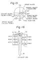
- both of the exhaust ports 32a and 32b may be constituted as eccentric ports which are arranged in the direction perpendicular to a line along which the respective cylinders are aligned, as shown in Fig. 12.
- both of the intake ports 32a and 32b are also arranged in the direction perpendicular to the line along which the cylinders are aligned.
- the maskings 5 formed on the wall of the cylinder head 6 may be desirably constituted as maskings 5a and 5b, as shown in Figs. 13 and 14.
- the masking 5a is formed between the intake valve 21a and the exhaust valve 31a and has a shape such that fresh air flowing from the intake port 20a into the combustion chamber 2 is prevented from flowing through the exhaust port 32a.
- the masking 5b is formed between the intake valve 21b and the exhaust valve 31b and has a shape such that exhaust gas or fresh air flowing from the exhaust port 32b back to the combustion chamber 2 is prevented from flowing through the intake port 20b.
- the exhaust valves 31a and 31b are closed earlier than the intake valves 21a and 21b.
- the intake valves 21a and 21b may be closed earlier at a crank angle of +40°, so that the intake valves 21a and 21b are already closed when the fresh air flows from the exhaust valves 31a and 31b back to the combustion chamber 2, to prevent the fresh air from flowing back through the intake ports 20a and 20b and to increase the real compression ratio of the fresh air in the cylinder chamber 2.
- exhaust pipes 52 connected to exhaust ports 51 of the respective cylinders are connected to a bypass passage 53 which can be separated by means of an exhaust control valve 34 into two cylinder groups of Nos. 1 through 3 and Nos. 4 through 6.
- the bypass passage 53 is connected at the downstream side thereof to a single exhaust pipe 38.
- the three exhaust pipes 52 in the same cylinder group can be arranged to each other, so that the exhaust pipes or the like can be more easily arranged and the exhaust pulsation can be more effectively used.
- a two-cycle engine according to the present invention may have three cylinders, or one or two cylinders.
- exhaust pipes 41 of the respective cylinders are arranged independently to each other and bypass valves 42 are provided to mutually connect these exhaust pipes 41.
- these bypass valves 42 are closed, so that the effective length of each exhaust pipe 41 becomes longer and an exhaust pulsation is not exerted on the exhaust pipes 41 of the other cylinders. Therefore, in this condition, the back (exhaust gas) pressure is always substantially positive.
- these bypass valves 42 are opened, so that each exhaust pipe 41 is subjected to a blowdown M of back pressure in the other cylinder having a cycle delayed by 120°, as shown in Fig. 18 and, therefore, charging effects due to exhaust pulsation, as mentioned above, can be expected.
- each exhaust pipe 61 of the respective cylinders is connected to a single pipe. Therefore, according to this embodiment, in the heavy load condition, each exhaust pipe 61 is subjected to a blowdown of back pressure in the other cylinder having a cycle delayed by 120° and, therefore, exhaust pulsation charging effects also can be expected, in the same manner as mentioned above.
- an exhaust pipe 43 is provided with an exhaust control valve 45 and a passage 44 for bypassing the valve 45.
- the valve 45 In the idling or light load condition, the valve 45 is closed, so that the effective length of the exhaust pipe 43 becomes substantially longer and, therefore, the back (exhaust gas) pressure is always substantially positive in this condition.
- the valve 45 In the heavy load condition, the valve 45 is opened, so that effective length of the exhaust pipe 43 becomes substantially shorter.
- Reference numeral 46 indicates a portion opened to the atmosphere; and 47, a volume (Fig. 20). In a one or two-cylinder engine, however, the charging effects of exhaust pulsation cannot be expected.
- a two-cycle engine according to the present invention also may be constituted as a diesel engine, as shown in Figs. 22 and 23.
- a stratification can be also obtained between the fresh air before fuel injection and the exhaust gas. After the fresh air is sufficiently heated by the exhaust gas, fuel is injected directly into the combustion chamber and, therefore, it is possible that the fresh air will self-ignite without ignition by a spark plug even at a relativey low compression ratio.
- Figs. 22 and 23 are views similar to Figs. 1 and 3, respectively, in which the same or corresponding parts as those in Figs. 1 and 3 are indicated by the same reference numerals.
- a single fuel injector 19 is provided in place of a spark plug 4 (Fig.
- the exhaust system is divided into two groups 70a and 70b for the cylinder Nos. 1, 2, and 3, cylinder Nos. 4, 5, and 6, respectively.
- a particle trapper or fixed-throttle 71 and a muffer 36 are provided independently in each of the exhaust systems 70a and 70b.
Landscapes
- Engineering & Computer Science (AREA)
- Chemical & Material Sciences (AREA)
- Combustion & Propulsion (AREA)
- Mechanical Engineering (AREA)
- General Engineering & Computer Science (AREA)
- Combustion Methods Of Internal-Combustion Engines (AREA)
- Characterised By The Charging Evacuation (AREA)
Applications Claiming Priority (8)
| Application Number | Priority Date | Filing Date | Title |
|---|---|---|---|
| JP61135054A JPS62291427A (ja) | 1986-06-12 | 1986-06-12 | 2サイクル内燃機関 |
| JP135054/86 | 1986-06-12 | ||
| JP61149705A JPS639628A (ja) | 1986-06-27 | 1986-06-27 | 2サイクル内燃機関 |
| JP149707/86 | 1986-06-27 | ||
| JP149705/86 | 1986-06-27 | ||
| JP149706/86 | 1986-06-27 | ||
| JP61149706A JPS639629A (ja) | 1986-06-27 | 1986-06-27 | 2サイクル内燃機関 |
| JP61149707A JPS639627A (ja) | 1986-06-27 | 1986-06-27 | 2サイクル内燃機関 |
Publications (3)
| Publication Number | Publication Date |
|---|---|
| EP0249129A2 true EP0249129A2 (fr) | 1987-12-16 |
| EP0249129A3 EP0249129A3 (en) | 1989-06-14 |
| EP0249129B1 EP0249129B1 (fr) | 1991-03-06 |
Family
ID=27471886
Family Applications (1)
| Application Number | Title | Priority Date | Filing Date |
|---|---|---|---|
| EP87107969A Expired - Lifetime EP0249129B1 (fr) | 1986-06-12 | 1987-06-02 | Moteur à combustion interne du type à deux temps |
Country Status (5)
| Country | Link |
|---|---|
| US (1) | US4732124A (fr) |
| EP (1) | EP0249129B1 (fr) |
| AU (1) | AU579518B2 (fr) |
| CA (1) | CA1297412C (fr) |
| DE (1) | DE3768340D1 (fr) |
Cited By (7)
| Publication number | Priority date | Publication date | Assignee | Title |
|---|---|---|---|---|
| DE3800651A1 (de) * | 1987-01-13 | 1988-07-21 | Toyota Motor Co Ltd | Zweitakt-brennkraftmaschine mit zylinderkopfventilen |
| EP0279429A3 (en) * | 1987-02-18 | 1989-09-06 | Toyota Jidosha Kabushiki Kaisha | Two-stroke internal combustion engine with cylinder head valves |
| EP0375789A4 (en) * | 1988-07-01 | 1990-12-12 | Toyota Jidosha Kabushiki Kaisha | Two-cycle internal combustion engine |
| WO1992014914A1 (fr) * | 1991-02-21 | 1992-09-03 | Vickers Plc | Systeme de commande du gaz d'echappement |
| EP0406078B1 (fr) * | 1989-06-30 | 1993-12-01 | Institut Français du Pétrole | Moteur deux temps à boisseaux tournants et utilisations d'un tel moteur |
| WO2015011390A1 (fr) * | 2013-07-23 | 2015-01-29 | Societe De Motorisations Aeronautiques | Procédé de pilotage d'un moteur deux-temps a combustion interne |
| WO2015079078A1 (fr) * | 2013-11-29 | 2015-06-04 | Nairex Business, S.L. | Moteur à combustion interne comprenant plusieurs admissions indépendantes |
Families Citing this family (12)
| Publication number | Priority date | Publication date | Assignee | Title |
|---|---|---|---|---|
| US4823755A (en) * | 1987-01-27 | 1989-04-25 | Toyota Jidosha Kabushiki Kaisha | Fuel injection system for an internal combustion engine |
| US4883030A (en) * | 1987-11-26 | 1989-11-28 | Toyota Jidosha Kabushiki Kaisha | Combustion chamber of a two-stroke engine |
| US4945867A (en) * | 1988-08-12 | 1990-08-07 | Toyota Jidosha Kabushiki Kaisha | Two-stroke engine |
| JPH0733766B2 (ja) * | 1988-08-30 | 1995-04-12 | トヨタ自動車株式会社 | 内燃機関の燃焼室 |
| US5101626A (en) * | 1990-07-19 | 1992-04-07 | Outboard Marine Corporation | Exhaust gas discharge system for two-stroke internal combustion engine |
| JP2929781B2 (ja) * | 1991-06-28 | 1999-08-03 | 三菱自動車工業株式会社 | 燃料噴射時期制御式層状燃焼内燃機関 |
| US5239960A (en) * | 1991-07-30 | 1993-08-31 | Mazda Motor Corporation | Engine induction system provided with a mechanical supercharger |
| US5437155A (en) * | 1993-10-13 | 1995-08-01 | Outboard Marine Corporation | Outboard motor exhaust system |
| JPH08284697A (ja) * | 1995-04-17 | 1996-10-29 | Yamaha Motor Co Ltd | 排気制御装置を備えるエンジン |
| FR2768180B1 (fr) * | 1997-09-09 | 1999-10-08 | Inst Francais Du Petrole | Procede de fonctionnement d'un moteur 4 temps, en auto-allumage controle |
| FR2886342B1 (fr) * | 2005-05-24 | 2010-08-27 | Inst Francais Du Petrole | Procede de controle du balayage des gaz brules d'un moteur a injection indirecte, notamment moteur suralimente, et moteur utilisant un tel procede |
| US7673617B2 (en) * | 2007-06-14 | 2010-03-09 | Institut Francis Du Petrole | Indirect-injection internal-combustion engine, notably spark-ignition supercharged engine, with two intake means for carrying out a burnt gas scavenging stage |
Family Cites Families (16)
| Publication number | Priority date | Publication date | Assignee | Title |
|---|---|---|---|---|
| US2958315A (en) * | 1959-05-18 | 1960-11-01 | Power Brake Equipment Company | Two stroke cycle engine brake |
| US3808807A (en) * | 1971-08-27 | 1974-05-07 | Brunswick Corp | Tuning arrangement for outboard motor |
| JPS4851126A (fr) * | 1971-11-01 | 1973-07-18 | ||
| AU525683B2 (en) * | 1976-12-21 | 1982-11-25 | Malz Nominees Pty. Ltd. | Internal combustion engine |
| AU511290B2 (en) * | 1977-12-19 | 1980-08-07 | Nissan Motor Company Limited | Dual induction system fori. C. engine |
| FR2420034A1 (fr) * | 1978-03-14 | 1979-10-12 | Soubis Jean Pierre | Perfectionnements a des moteurs deux temps ameliorant la combustion et permettant une reduction de la pollution |
| US4357917A (en) * | 1978-05-15 | 1982-11-09 | Nissan Motor Company, Limited | Variable valve timing system for induction control of an internal combustion engine |
| US4543928A (en) * | 1980-06-13 | 1985-10-01 | Von Seggern Ernest | Two cycle engine with dynamic stratification and method of operation therefor |
| JPS5922250A (ja) * | 1982-07-26 | 1984-02-04 | Sanyo Electric Co Ltd | ピツクアツプの走査針 |
| JPS59188014A (ja) * | 1983-03-24 | 1984-10-25 | Mazda Motor Corp | エンジンのバルブタイミング制御装置 |
| JPS605770A (ja) * | 1983-06-22 | 1985-01-12 | Hitachi Ltd | 光サイリスタのゲ−ト駆動回路 |
| US4548175A (en) * | 1983-12-05 | 1985-10-22 | Toyota Jidosha Kabushiki Kaisha | Internal combustion engine with two intake valves |
| JPS60164608A (ja) * | 1984-02-06 | 1985-08-27 | Mazda Motor Corp | デイ−ゼルエンジンの排気弁制御装置 |
| JPS60247006A (ja) * | 1984-05-22 | 1985-12-06 | Yoichi Yamazaki | 多気筒エンジンの排気装置 |
| JPS611656U (ja) * | 1984-06-10 | 1986-01-08 | マツダ株式会社 | デイ−ゼルエンジンの吸気装置 |
| US4616605A (en) * | 1984-12-31 | 1986-10-14 | Kline Herbert E | Two-cycle engine with improved scavenging |
-
1987
- 1987-05-21 US US07/052,418 patent/US4732124A/en not_active Expired - Fee Related
- 1987-06-02 DE DE8787107969T patent/DE3768340D1/de not_active Expired - Lifetime
- 1987-06-02 EP EP87107969A patent/EP0249129B1/fr not_active Expired - Lifetime
- 1987-06-09 CA CA000539178A patent/CA1297412C/fr not_active Expired - Lifetime
- 1987-06-10 AU AU74069/87A patent/AU579518B2/en not_active Ceased
Cited By (9)
| Publication number | Priority date | Publication date | Assignee | Title |
|---|---|---|---|---|
| DE3800651A1 (de) * | 1987-01-13 | 1988-07-21 | Toyota Motor Co Ltd | Zweitakt-brennkraftmaschine mit zylinderkopfventilen |
| EP0279429A3 (en) * | 1987-02-18 | 1989-09-06 | Toyota Jidosha Kabushiki Kaisha | Two-stroke internal combustion engine with cylinder head valves |
| EP0375789A4 (en) * | 1988-07-01 | 1990-12-12 | Toyota Jidosha Kabushiki Kaisha | Two-cycle internal combustion engine |
| US5062395A (en) * | 1988-07-01 | 1991-11-05 | Toyota Jidosha Kabushiki Kaisha | Two-stroke internal combustion engine |
| EP0406078B1 (fr) * | 1989-06-30 | 1993-12-01 | Institut Français du Pétrole | Moteur deux temps à boisseaux tournants et utilisations d'un tel moteur |
| WO1992014914A1 (fr) * | 1991-02-21 | 1992-09-03 | Vickers Plc | Systeme de commande du gaz d'echappement |
| WO2015011390A1 (fr) * | 2013-07-23 | 2015-01-29 | Societe De Motorisations Aeronautiques | Procédé de pilotage d'un moteur deux-temps a combustion interne |
| FR3009025A1 (fr) * | 2013-07-23 | 2015-01-30 | Motorisations Aeronautiques | Procede de pilotage d'un moteur deux-temps a combustion interne |
| WO2015079078A1 (fr) * | 2013-11-29 | 2015-06-04 | Nairex Business, S.L. | Moteur à combustion interne comprenant plusieurs admissions indépendantes |
Also Published As
| Publication number | Publication date |
|---|---|
| AU579518B2 (en) | 1988-11-24 |
| EP0249129A3 (en) | 1989-06-14 |
| AU7406987A (en) | 1988-01-07 |
| EP0249129B1 (fr) | 1991-03-06 |
| US4732124A (en) | 1988-03-22 |
| CA1297412C (fr) | 1992-03-17 |
| DE3768340D1 (de) | 1991-04-11 |
Similar Documents
| Publication | Publication Date | Title |
|---|---|---|
| US4732117A (en) | Two-cycle internal combustion engine | |
| US4732118A (en) | Two-cycle internal combustion engine | |
| US4732116A (en) | Two-cycle internal combustion engine | |
| EP0249129B1 (fr) | Moteur à combustion interne du type à deux temps | |
| US4856473A (en) | Internal combustion engine with multiple intake valves and EGR arrangement | |
| JPH086585B2 (ja) | 2サイクル内燃機関 | |
| EP1179676A1 (fr) | Moteur à combustion interne à injection directe | |
| JP2966008B2 (ja) | エンジンの過給装置 | |
| US4781154A (en) | Two-cycle internal combustion engine | |
| JPS63201341A (ja) | 2サイクル内燃機関 | |
| JPS639627A (ja) | 2サイクル内燃機関 | |
| JPH0568608B2 (fr) | ||
| EP0057591A2 (fr) | Moteur à combustion interne | |
| JPH03151532A (ja) | 2サイクルエンジン | |
| JPS63201312A (ja) | 2サイクル内燃機関 | |
| JPH0828280A (ja) | 過給機を備えるエンジンの吸気装置 | |
| JPS63173814A (ja) | 2サイクル内燃機関 | |
| JPS6312818A (ja) | 2サイクル内燃機関 | |
| JPH072978Y2 (ja) | 2サイクル内燃機関 | |
| JP2647131B2 (ja) | 過給機付ディーゼルエンジンの吸気装置 | |
| JPS639628A (ja) | 2サイクル内燃機関 | |
| JPH0513954Y2 (fr) | ||
| JPS63205415A (ja) | 2サイクル内燃機関 | |
| JPS63201313A (ja) | 2サイクル内燃機関 | |
| JPH03149328A (ja) | 2サイクルエンジン |
Legal Events
| Date | Code | Title | Description |
|---|---|---|---|
| PUAI | Public reference made under article 153(3) epc to a published international application that has entered the european phase |
Free format text: ORIGINAL CODE: 0009012 |
|
| 17P | Request for examination filed |
Effective date: 19870602 |
|
| AK | Designated contracting states |
Kind code of ref document: A2 Designated state(s): CH DE FR GB IT LI SE |
|
| PUAL | Search report despatched |
Free format text: ORIGINAL CODE: 0009013 |
|
| AK | Designated contracting states |
Kind code of ref document: A3 Designated state(s): CH DE FR GB IT LI SE |
|
| 17Q | First examination report despatched |
Effective date: 19900228 |
|
| GRAA | (expected) grant |
Free format text: ORIGINAL CODE: 0009210 |
|
| AK | Designated contracting states |
Kind code of ref document: B1 Designated state(s): CH DE FR GB IT LI SE |
|
| ET | Fr: translation filed | ||
| ITF | It: translation for a ep patent filed | ||
| REF | Corresponds to: |
Ref document number: 3768340 Country of ref document: DE Date of ref document: 19910411 |
|
| PLBE | No opposition filed within time limit |
Free format text: ORIGINAL CODE: 0009261 |
|
| STAA | Information on the status of an ep patent application or granted ep patent |
Free format text: STATUS: NO OPPOSITION FILED WITHIN TIME LIMIT |
|
| 26N | No opposition filed | ||
| EAL | Se: european patent in force in sweden |
Ref document number: 87107969.5 |
|
| PGFP | Annual fee paid to national office [announced via postgrant information from national office to epo] |
Ref country code: GB Payment date: 19970527 Year of fee payment: 11 |
|
| PGFP | Annual fee paid to national office [announced via postgrant information from national office to epo] |
Ref country code: DE Payment date: 19970606 Year of fee payment: 11 |
|
| PGFP | Annual fee paid to national office [announced via postgrant information from national office to epo] |
Ref country code: FR Payment date: 19970610 Year of fee payment: 11 |
|
| PGFP | Annual fee paid to national office [announced via postgrant information from national office to epo] |
Ref country code: SE Payment date: 19970618 Year of fee payment: 11 Ref country code: CH Payment date: 19970618 Year of fee payment: 11 |
|
| PG25 | Lapsed in a contracting state [announced via postgrant information from national office to epo] |
Ref country code: GB Free format text: LAPSE BECAUSE OF NON-PAYMENT OF DUE FEES Effective date: 19980602 |
|
| PG25 | Lapsed in a contracting state [announced via postgrant information from national office to epo] |
Ref country code: SE Free format text: LAPSE BECAUSE OF NON-PAYMENT OF DUE FEES Effective date: 19980603 |
|
| PG25 | Lapsed in a contracting state [announced via postgrant information from national office to epo] |
Ref country code: LI Free format text: LAPSE BECAUSE OF NON-PAYMENT OF DUE FEES Effective date: 19980630 Ref country code: CH Free format text: LAPSE BECAUSE OF NON-PAYMENT OF DUE FEES Effective date: 19980630 |
|
| GBPC | Gb: european patent ceased through non-payment of renewal fee |
Effective date: 19980602 |
|
| REG | Reference to a national code |
Ref country code: CH Ref legal event code: PL |
|
| PG25 | Lapsed in a contracting state [announced via postgrant information from national office to epo] |
Ref country code: FR Free format text: LAPSE BECAUSE OF NON-PAYMENT OF DUE FEES Effective date: 19990226 |
|
| EUG | Se: european patent has lapsed |
Ref document number: 87107969.5 |
|
| PG25 | Lapsed in a contracting state [announced via postgrant information from national office to epo] |
Ref country code: DE Free format text: LAPSE BECAUSE OF NON-PAYMENT OF DUE FEES Effective date: 19990401 |
|
| REG | Reference to a national code |
Ref country code: FR Ref legal event code: ST |
|
| PG25 | Lapsed in a contracting state [announced via postgrant information from national office to epo] |
Ref country code: IT Free format text: LAPSE BECAUSE OF NON-PAYMENT OF DUE FEES;WARNING: LAPSES OF ITALIAN PATENTS WITH EFFECTIVE DATE BEFORE 2007 MAY HAVE OCCURRED AT ANY TIME BEFORE 2007. THE CORRECT EFFECTIVE DATE MAY BE DIFFERENT FROM THE ONE RECORDED. Effective date: 20050602 |