EP0249489A2 - Elektromagnetische Kupplung - Google Patents
Elektromagnetische Kupplung Download PDFInfo
- Publication number
- EP0249489A2 EP0249489A2 EP87305218A EP87305218A EP0249489A2 EP 0249489 A2 EP0249489 A2 EP 0249489A2 EP 87305218 A EP87305218 A EP 87305218A EP 87305218 A EP87305218 A EP 87305218A EP 0249489 A2 EP0249489 A2 EP 0249489A2
- Authority
- EP
- European Patent Office
- Prior art keywords
- shaft
- rotor
- yoke
- rotation shaft
- electromagnetic clutch
- Prior art date
- Legal status (The legal status is an assumption and is not a legal conclusion. Google has not performed a legal analysis and makes no representation as to the accuracy of the status listed.)
- Withdrawn
Links
Images

Classifications
-
- F—MECHANICAL ENGINEERING; LIGHTING; HEATING; WEAPONS; BLASTING
- F16—ENGINEERING ELEMENTS AND UNITS; GENERAL MEASURES FOR PRODUCING AND MAINTAINING EFFECTIVE FUNCTIONING OF MACHINES OR INSTALLATIONS; THERMAL INSULATION IN GENERAL
- F16D—COUPLINGS FOR TRANSMITTING ROTATION; CLUTCHES; BRAKES
- F16D27/00—Magnetically- or electrically- actuated clutches; Control or electric circuits therefor
- F16D27/10—Magnetically- or electrically- actuated clutches; Control or electric circuits therefor with an electromagnet not rotating with a clutching member, i.e. without collecting rings
- F16D27/108—Magnetically- or electrically- actuated clutches; Control or electric circuits therefor with an electromagnet not rotating with a clutching member, i.e. without collecting rings with axially movable clutching members
- F16D27/112—Magnetically- or electrically- actuated clutches; Control or electric circuits therefor with an electromagnet not rotating with a clutching member, i.e. without collecting rings with axially movable clutching members with flat friction surfaces, e.g. discs
-
- F—MECHANICAL ENGINEERING; LIGHTING; HEATING; WEAPONS; BLASTING
- F16—ENGINEERING ELEMENTS AND UNITS; GENERAL MEASURES FOR PRODUCING AND MAINTAINING EFFECTIVE FUNCTIONING OF MACHINES OR INSTALLATIONS; THERMAL INSULATION IN GENERAL
- F16D—COUPLINGS FOR TRANSMITTING ROTATION; CLUTCHES; BRAKES
- F16D27/00—Magnetically- or electrically- actuated clutches; Control or electric circuits therefor
- F16D2027/008—Details relating to the magnetic circuit, or to the shape of the clutch parts to achieve a certain magnetic path
Definitions
- the present invention relates to an electromagnetic clutch and relates particularly although not exclusively to an electromagnetic microclutches for use in automation appliances.
- FIG. 1 illustrates a typical example of the conventional electromagnetic microclutch.
- This electromagnetic clutch has a hollow cylindrical rotor shaft 2 formed of a synthetic resin by molding.
- the rotor shaft 2 has a rotor 3, mounted around on it, and an annular yoke 4 rotatably mounted on it so as to be positioned on the left side in FIG. 1 with respect to the rotor 3.
- the rotor 3 has a boss 5 and a cup-shaped flange portion 6 concentrically and integrally formed with the boss 5, the flange portion 6 having an outer circumferential magnetic pole 6a and an inner circumferential magnetic pole 6b.
- the yoke 4 has a coil 7 and a yoke locking plate 8 welded to it.
- the yoke locking plate 8 is provided in its distal end with an engaging recess 8a, into which a lock pin 9 fits.
- the lock pin 9 is attached at its proximal end to a frame 10 for keeping the locking plate 8 stationary, so that the yoke 4 is prevented from accompanying the rotor shaft 2 when the latter is rotated.
- a spur gear 11 rotatably fits around the rotor shaft 2 and is prevented from axial movement by both the boss 5 of the rotor 3 and a retaining ring 12 mounted to the rotor shaft 2.
- a ring-shaped armature 13 is fixed to the spur gear 11 through a ring-shaped spring plate 14 so that one face thereof faces to the inner and outer magnetic poles 6b and 6a with a small gap.
- the armature 13 is rotated together with the spur gear 11 when a rotation force is transmitted from a drive mechanism (not shown), including an electric motor, to the spur gear 11.
- the coil 7 is energized for magnetizing the yoke 4, so that a magnetic flux passes the yoke 4, the outer circumferential magnetic pole 6a of the rotor 3, the armature 13 and the inner circumferential magnetic pole 6b and then returns to the yoke 4, thus forming a magnetic path ⁇ 1.
- the armature 13 is hence brought into contact with the magnetic poles 6a and 6b by magnetic attraction against the resilient force exerted by the spring plate 14, so that the rotation shaft 2 is rotated.
- the coil 7 is deenergized, the armature 13 is separated from the rotor 3 by the resilient force of the spring plate 14, with the result that transmission of the torque from the spur gear 11 to the rotation shaft 2 is discontinued.
- Such an electromagnetic clutch has the following problems in size reduction:
- the present invention provides an electromagnetic clutch of the type which includes a rotor secured around a rotation shaft, a drive member rotatably mounted around the rotation shaft, an armature mounted through a resilient member to the drive member with a gap to the rotor, a bearing mounted around the rotation shaft, a yoke mounted around the bearing for rotation about the rotation shaft, and the yoke locking mechanism for locking the yoke to a frame so as to prevent the yoke from accompanying the rotation shaft when the rotation shaft is rotated, the yoke having a coil wound therearound, and in which the rotor, the armature and the yoke are arranged to form a magnetic path so that the armature is electromagnetically attracted to the rotor for transmitting torque from the drive member to the rotation shaft when the coil is energized.
- the rotation shaft includes: a first sintered compact shaft made of a first magnetic alloy, the first shaft having the bearing fitted therearound; and a second sintered compact shaft, concentrically jointed to the first shaft for transmitting the torque to the first shaft, the second shaft being made of a second magnetic alloy, the second shaft having both the rotor and the drive member placed therearound.
- the rotor shaft which is made of a compacted, sintered magnetic material allows a highly efficient magnetic path to be formed as compared to the prior art synthetic resin rotor shaft and thus, it enables reduction in size of both the coil and the yoke. Further, the rotor shaft according to the present invention may be reduced in thickness because of its high strength as compared to that of the synthetic resin rotor shaft.
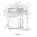
- an electromagnetic clutch 20, constructed according to the present invention includes a rotor shaft 21 which has a rotor boss 22 and a collar 23 fitted into the rotor boss 22.
- the rotor boss 22 is made of a conventional sintered magnetic ferroalloy and is manufactured by compression molding and then sintering the magnetic material.
- the collar 23 is also an oil-impregnated, sintered compact of another magnetic ferroalloy.
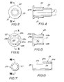
- the rotor boss 22 is in a generally hollow cylindrical shape and has a engaging hole 24 having a D-profile periphery axially passing through it.
- the engaging hole 24 is defined by both an arcuate wall 24a and a chord wall 24b.
- the rotor boss 22 has an annular flange 22a, formed at its one end to project radially outwards, and a pair of projections 22b and 22b formed at the other end to be located at an angular interval of 180° about its axis A for holding the collar between them.
- the collar 23 has a hollow cylindrical rotor mounting portion 25 and a C-profile connecting portion 27 integrally and coaxially formed with the rotor mounting portion 25, thus forming a pair of parallel axial edges 27a and 27a.
- the connecting portion 27 is formed so that it snugly fits into the engaging hole 24 of the rotor boss 22.
- the rotor mounting portion 25 has an annular retaining groove 25a into which a retaining ring 12 fits.
- the rotor boss 22 and the collar 23 are interconnected by fitting the connecting portion 27 into the rotor boss 22 as illustrated in FIG. 4.
- the inner edge 25b of the rotor mounting portion 25 is in abuttment with the other end of the rotor boss 22, and the two parallel edges 27a and 27a of the connecting portion 27 are in contact with the chord wall 24b of the rotor boss 22.
- the collar 23 has a generally disc-shaped rotor 40 mounted around it by a conventional key-keyway mechanism.
- the rotor 40 includes an outer circumferential magnetic pole 40a and an inner circumferential magnetic pole 40b, both the poles 40a and 40b being concentrically formed.
- Arranged on the left side in FIG. 2 with respect to the rotor 40 is a generally channel-shaped annular yoke 41 which includes an inner annual flange 41a and an outer annular flange 41b, both the flanges axially extending.
- the yoke 4 has a coil bobbin 42 mounted to the outer face of the inner annular flange 41a.
- the coil bobbin 42 slidably fits around an oilless bearing 26, which in turn slidably fits around the rotor boss 22, thus supporting the yoke 41 so as to be rotatable relative to the rotor boss 22.
- the coil bobbin 42 has a coil 28, wound around it, and an elongated yoke locking portion 43 which radially outwardly extends from it and passes through a through slot 44 formed in the distal edge of the outer annular flange 41b of the yoke 41.
- the yoke locking portion 43 has a through slot 45 formed through at its distal end, and although not shown in FIG. 2, a lock pin similar to the lock pin 9 (FIG.
- a ring-shaped slider 29 is mounted around the rotor boss 22 and sandwiched between the left hand end in FIG. 2 of the yoke 41 and the annular flange 22a of the rotor boss 22 for smoothly sliding the rotor shaft 21.
- a spur gear 33 is slidably mounted around the collar 23 of the rotor shaft 21 and is prevented from axial movement by the retainer ring 12.
- a ring-shaped armature 30 is attached through a spring disc 31 to the spur gear 33 so that a small gap is formed between the rotor 40 and the armature 30.
- the armature 30 has a plurality of fastening holes 46 formed through it although only one fastening hole 46 is shown in FIG. 2.
- the spring disc 31 fits around a hub 33a of the spur gear 33 and is fastened to the spur gear 33 by means of machine screws 32 which pass through fastening holes 46 of the armature 30.
- a magnetic path ⁇ 2 which passes through part of the rotor shaft 21 is formed, that is, the yoke 41, the rotor shaft 21, the inner magnetic pole 40b, the armature 30, the outer magnetic pole 40 and the yoke 41 form the magnetic path.
- the armature 30 is magnetically attracted to the rotor 40, so that torque is transmitted from the spur gear 33 to the collar 23 and then to the rotor boss 22.
- torque is transmitted from the spur gear 33 to the rotor shaft 21, but may be transmitted from the latter to the former.
Landscapes
- Engineering & Computer Science (AREA)
- General Engineering & Computer Science (AREA)
- Physics & Mathematics (AREA)
- Electromagnetism (AREA)
- Mechanical Engineering (AREA)
- Braking Arrangements (AREA)
- Connection Of Motors, Electrical Generators, Mechanical Devices, And The Like (AREA)
- Mechanical Operated Clutches (AREA)
Applications Claiming Priority (2)
| Application Number | Priority Date | Filing Date | Title |
|---|---|---|---|
| JP90043/86U | 1986-06-13 | ||
| JP1986090043U JPS62202530U (de) | 1986-06-13 | 1986-06-13 |
Publications (2)
| Publication Number | Publication Date |
|---|---|
| EP0249489A2 true EP0249489A2 (de) | 1987-12-16 |
| EP0249489A3 EP0249489A3 (de) | 1988-02-24 |
Family
ID=13987611
Family Applications (1)
| Application Number | Title | Priority Date | Filing Date |
|---|---|---|---|
| EP87305218A Withdrawn EP0249489A3 (de) | 1986-06-13 | 1987-06-12 | Elektromagnetische Kupplung |
Country Status (3)
| Country | Link |
|---|---|
| US (1) | US4804874A (de) |
| EP (1) | EP0249489A3 (de) |
| JP (1) | JPS62202530U (de) |
Cited By (2)
| Publication number | Priority date | Publication date | Assignee | Title |
|---|---|---|---|---|
| US4955954A (en) * | 1988-07-04 | 1990-09-11 | Mitsubishi Denki Kabushiki Kaisha | Motor-driven control apparatus |
| CN108980229A (zh) * | 2017-06-02 | 2018-12-11 | 苏州采奕动力科技有限公司 | 一种汽车电动门电磁离合器 |
Families Citing this family (5)
| Publication number | Priority date | Publication date | Assignee | Title |
|---|---|---|---|---|
| JPH0678771B2 (ja) * | 1988-08-05 | 1994-10-05 | 神鋼電機株式会社 | 電磁クラッチ |
| US5762173A (en) * | 1995-04-25 | 1998-06-09 | Mita Industrial Co., Ltd. | Electromagnetic clutch |
| JPH09149584A (ja) * | 1995-11-20 | 1997-06-06 | Matsushita Electric Ind Co Ltd | スピンドルモータ |
| JP2001221656A (ja) * | 2000-02-04 | 2001-08-17 | Asmo Co Ltd | モータアクチュエータ |
| JP5658046B2 (ja) * | 2011-01-21 | 2015-01-21 | Ntn株式会社 | 回転伝達装置 |
Family Cites Families (10)
| Publication number | Priority date | Publication date | Assignee | Title |
|---|---|---|---|---|
| US2134795A (en) * | 1936-07-14 | 1938-11-01 | Us Electrical Motors Inc | Magnetic structure for dynamoelectric machines |
| US2834895A (en) * | 1954-07-08 | 1958-05-13 | Papst Hermann | Electric rotary-field system |
| US3263784A (en) * | 1964-03-30 | 1966-08-02 | Pitts Ind Inc | Magnetic clutch |
| US3465181A (en) * | 1966-06-08 | 1969-09-02 | Fasco Industries | Rotor for fractional horsepower torque motor |
| US3668445A (en) * | 1970-12-21 | 1972-06-06 | Leroy K Grove | Electromagnet for brakes and clutches |
| US3872334A (en) * | 1972-04-14 | 1975-03-18 | Robert J Loubier | Integral rotor and gear assembly |
| JPS541809A (en) * | 1977-06-07 | 1979-01-09 | Citizen Watch Co Ltd | Rotor magnetic and its manufacture |
| GB2034830B (en) * | 1978-10-13 | 1982-10-20 | Servicon Clutches Ltd | Wrap spring clutches |
| US4508203A (en) * | 1982-07-19 | 1985-04-02 | Facet Enterprises, Incorporated | Plastic bobbin for electromagnetic clutch |
| JPS6249025A (ja) * | 1985-08-27 | 1987-03-03 | Sanden Corp | 電磁クラツチ |
-
1986
- 1986-06-13 JP JP1986090043U patent/JPS62202530U/ja active Pending
-
1987
- 1987-06-10 US US07/060,216 patent/US4804874A/en not_active Expired - Fee Related
- 1987-06-12 EP EP87305218A patent/EP0249489A3/de not_active Withdrawn
Cited By (2)
| Publication number | Priority date | Publication date | Assignee | Title |
|---|---|---|---|---|
| US4955954A (en) * | 1988-07-04 | 1990-09-11 | Mitsubishi Denki Kabushiki Kaisha | Motor-driven control apparatus |
| CN108980229A (zh) * | 2017-06-02 | 2018-12-11 | 苏州采奕动力科技有限公司 | 一种汽车电动门电磁离合器 |
Also Published As
| Publication number | Publication date |
|---|---|
| US4804874A (en) | 1989-02-14 |
| JPS62202530U (de) | 1987-12-24 |
| EP0249489A3 (de) | 1988-02-24 |
Similar Documents
| Publication | Publication Date | Title |
|---|---|---|
| US3185276A (en) | Electro-magnetically actuated normally disengaged spring clutches | |
| EP0013175B1 (de) | Elektromagnetisch betätigte Kupplung | |
| US3735847A (en) | Electromagnetic spring-wound clutch | |
| US4744449A (en) | Compact electromagnetic tooth clutch | |
| JPS5842371B2 (ja) | デンジクラツチ | |
| US3854562A (en) | Electromagnetic clutch | |
| US5971121A (en) | Mag stop clutch with center pole | |
| US4694945A (en) | Electromagnetic clutch with an improved magnetic rotatable member | |
| US4804874A (en) | Electromagnetic clutch | |
| TW201307698A (zh) | 電磁離合器 | |
| US5148902A (en) | Electromagnetic coupling device | |
| US5059842A (en) | Electromagnetic clutch with grooved friction surface | |
| US6031309A (en) | Electromagnet clutch | |
| US4508203A (en) | Plastic bobbin for electromagnetic clutch | |
| US4664238A (en) | Electromagnetic coupling device | |
| US3978953A (en) | Resilient connection between inner and outer poles on electromagnetic clutch | |
| US4353450A (en) | Two stage disengagement spring for electromagnetic tooth clutches | |
| US5038905A (en) | Electromagnetic clutch | |
| JPS6146265Y2 (de) | ||
| EP0249490A2 (de) | Jochsperrvorrichtung für elektromagnetische Kupplungen | |
| EP0416178B1 (de) | Elektromagnetische Kupplung | |
| USRE30609E (en) | Resilient connection between inner and outer poles on electromagnetic clutch | |
| JPH085384Y2 (ja) | 電滋スプリングクラツチ | |
| JPH0317063Y2 (de) | ||
| JP3296916B2 (ja) | 電磁バネクラッチ |
Legal Events
| Date | Code | Title | Description |
|---|---|---|---|
| PUAI | Public reference made under article 153(3) epc to a published international application that has entered the european phase |
Free format text: ORIGINAL CODE: 0009012 |
|
| AK | Designated contracting states |
Kind code of ref document: A2 Designated state(s): DE FR GB NL |
|
| PUAL | Search report despatched |
Free format text: ORIGINAL CODE: 0009013 |
|
| AK | Designated contracting states |
Kind code of ref document: A3 Designated state(s): DE FR GB NL |
|
| STAA | Information on the status of an ep patent application or granted ep patent |
Free format text: STATUS: THE APPLICATION IS DEEMED TO BE WITHDRAWN |
|
| 18D | Application deemed to be withdrawn |
Effective date: 19880825 |
|
| RIN1 | Information on inventor provided before grant (corrected) |
Inventor name: NAKAMURA, HIROAKI |