EP0249655A1 - Arrangement assemblé multiple de pompes à membrane - Google Patents
Arrangement assemblé multiple de pompes à membrane Download PDFInfo
- Publication number
- EP0249655A1 EP0249655A1 EP86116315A EP86116315A EP0249655A1 EP 0249655 A1 EP0249655 A1 EP 0249655A1 EP 86116315 A EP86116315 A EP 86116315A EP 86116315 A EP86116315 A EP 86116315A EP 0249655 A1 EP0249655 A1 EP 0249655A1
- Authority
- EP
- European Patent Office
- Prior art keywords
- housings
- arms
- pumping plant
- pumping
- combined complex
- Prior art date
- Legal status (The legal status is an assumption and is not a legal conclusion. Google has not performed a legal analysis and makes no representation as to the accuracy of the status listed.)
- Withdrawn
Links
- 238000005086 pumping Methods 0.000 claims abstract description 84
- 239000007788 liquid Substances 0.000 claims abstract description 20
- 239000002002 slurry Substances 0.000 description 28
- 238000007599 discharging Methods 0.000 description 9
- 238000010276 construction Methods 0.000 description 6
- 238000000034 method Methods 0.000 description 6
- 230000008602 contraction Effects 0.000 description 4
- 238000010586 diagram Methods 0.000 description 3
- 230000000694 effects Effects 0.000 description 3
- 238000012423 maintenance Methods 0.000 description 3
- 238000007689 inspection Methods 0.000 description 2
- 230000002844 continuous effect Effects 0.000 description 1
- 238000005112 continuous flow technique Methods 0.000 description 1
- 238000007796 conventional method Methods 0.000 description 1
- 238000005520 cutting process Methods 0.000 description 1
- 125000004122 cyclic group Chemical group 0.000 description 1
- 238000013461 design Methods 0.000 description 1
- 239000003814 drug Substances 0.000 description 1
- 239000002440 industrial waste Substances 0.000 description 1
- 235000021056 liquid food Nutrition 0.000 description 1
- 238000004519 manufacturing process Methods 0.000 description 1
- 238000012856 packing Methods 0.000 description 1
- 230000008439 repair process Effects 0.000 description 1
- 230000035939 shock Effects 0.000 description 1
- XLYOFNOQVPJJNP-UHFFFAOYSA-N water Substances O XLYOFNOQVPJJNP-UHFFFAOYSA-N 0.000 description 1
Images

Classifications
-
- F—MECHANICAL ENGINEERING; LIGHTING; HEATING; WEAPONS; BLASTING
- F04—POSITIVE - DISPLACEMENT MACHINES FOR LIQUIDS; PUMPS FOR LIQUIDS OR ELASTIC FLUIDS
- F04B—POSITIVE-DISPLACEMENT MACHINES FOR LIQUIDS; PUMPS
- F04B43/00—Machines, pumps, or pumping installations having flexible working members
- F04B43/02—Machines, pumps, or pumping installations having flexible working members having plate-like flexible members, e.g. diaphragms
- F04B43/025—Machines, pumps, or pumping installations having flexible working members having plate-like flexible members, e.g. diaphragms two or more plate-like pumping members in parallel
-
- F—MECHANICAL ENGINEERING; LIGHTING; HEATING; WEAPONS; BLASTING
- F04—POSITIVE - DISPLACEMENT MACHINES FOR LIQUIDS; PUMPS FOR LIQUIDS OR ELASTIC FLUIDS
- F04B—POSITIVE-DISPLACEMENT MACHINES FOR LIQUIDS; PUMPS
- F04B43/00—Machines, pumps, or pumping installations having flexible working members
- F04B43/0009—Special features
- F04B43/0045—Special features with a number of independent working chambers which are actuated successively by one mechanism
-
- F—MECHANICAL ENGINEERING; LIGHTING; HEATING; WEAPONS; BLASTING
- F04—POSITIVE - DISPLACEMENT MACHINES FOR LIQUIDS; PUMPS FOR LIQUIDS OR ELASTIC FLUIDS
- F04B—POSITIVE-DISPLACEMENT MACHINES FOR LIQUIDS; PUMPS
- F04B43/00—Machines, pumps, or pumping installations having flexible working members
- F04B43/0009—Special features
- F04B43/0081—Special features systems, control, safety measures
-
- F—MECHANICAL ENGINEERING; LIGHTING; HEATING; WEAPONS; BLASTING
- F04—POSITIVE - DISPLACEMENT MACHINES FOR LIQUIDS; PUMPS FOR LIQUIDS OR ELASTIC FLUIDS
- F04B—POSITIVE-DISPLACEMENT MACHINES FOR LIQUIDS; PUMPS
- F04B53/00—Component parts, details or accessories not provided for in, or of interest apart from, groups F04B1/00 - F04B23/00 or F04B39/00 - F04B47/00
- F04B53/10—Valves; Arrangement of valves
-
- F—MECHANICAL ENGINEERING; LIGHTING; HEATING; WEAPONS; BLASTING
- F04—POSITIVE - DISPLACEMENT MACHINES FOR LIQUIDS; PUMPS FOR LIQUIDS OR ELASTIC FLUIDS
- F04B—POSITIVE-DISPLACEMENT MACHINES FOR LIQUIDS; PUMPS
- F04B53/00—Component parts, details or accessories not provided for in, or of interest apart from, groups F04B1/00 - F04B23/00 or F04B39/00 - F04B47/00
- F04B53/16—Casings; Cylinders; Cylinder liners or heads; Fluid connections
Definitions
- the disclosed techniques belong to the technical field of the construction of a high-pressure pump type pumping plant used to send under pressure a slurry of industrial waste to a solid-liquid separator, such as a filter press.
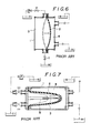
- the high-pressure pumps include in addition to a plunger type pump a so-called diaphragm type pump shown in Fig. 6 and used at present.
- this type of pump is provided in a housing 1 with a diaphragm 2, which defines a pressure chamber 3 and a pumping chamber 4 in the interior of the housing 1, and used as a high-pressure pump in which the compressing force against the pumping chamber is increased by the pressure put into the pressure chamber.
- a flexible rubber diaphragm 2 ⁇ having a U-shaped longitudinal section is provided expansibly and contractibly in a housing 1 to thereby define a pressure pump 3 and a pumping chamber 4 in the interior thereof, and the diaphragm 2 ⁇ is supported on the base end of an arm 5 which is moved axially with the diaphragm kept in a sealed state, whereby a large output can be applied to a slurry by a small compressive force.
- This super-high-pressure pumping plant is advantageous in that such a high output pressure that might cause an operating liquid consisting of an oil to leak from various portions, to which parts of the pumping plant are joined in a sealed state, of the housing can be obtained.
- this pumping plant which is constructed on the basis of the newly-developed techniques, still has some points to be improved.
- An object of the present invention is to give a solution to the technical problems included in a high-output pumping plant which is made on the basis of the above-described conventional techniques, and which has a flexible diaphragm having a U-shaped cross section, and provide an excellent combined complex pumping plant having a desired number of pumping units which are connected together mechanically so that they can be controlled easily, whereby an output per cycle of one pumping unit is smoothed to enable an easily-controllable, the smoothest possible high-output operation to be carried out; and contributing much to various industrial fields in which the pressure techniques are utilized.
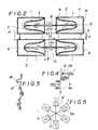
- Figs. 1-5 illustrate the embodiments of the present invention, wherein:
- reference numeral 6 denotes a combined complex pumping plant in which the gist of this invention resides.
- the plant in this embodiment is a twin type plant, in which a pair of housings 1, 1 are fixed to frames 7, 7 so that the housings extend in parallel with each other.
- Each housing 1 has a basically identical mode a a conventional housing of this kind.
- the housing 1 is provided therein with a rubber diaphragm 2 ⁇ , which has U-shaped longitudinal section, in such a manner that the diaphragm 2 ⁇ can be expanded and contracted mainly in the longitudinal direction and disassembled and replaced by another.
- the interior of the housing 1 is divided by this diaphragm 2 ⁇ into a pressure chamber 3 and a pumping chamber 4 which is on the opposite side of the pressure chamber 3.
- the diaphragm 2 ⁇ is fixed unitarily at the central portion thereof by a vulcanizing treatment to a base end of an arm 5 ⁇ which is slidable through a seal bearing 8 provided in one of a pair of vertically arranged walls of the housing 1, in such a manner that the diaphragm 2 ⁇ can be kept supported thereon even when it is in a contracted position.
- the arms 5 ⁇ inserted into the housings 1, 1 are connected to both ends of a connecting bar 10 by pins via slits, which connecting bar 10 is support pivotably by a pin on a bracket 9 fixed to the frame 7.
- a feed port 16 and a discharge port 17 for a liquid to be treated are provided in the other wall 7 ⁇ .
- the feed port 16 is communicated with a high-pressure pump 20 for a slurry tank 19 via a line provided with a check valve 18 and branching at an electromagnetic three-way valve 21.
- Each of the discharge ports 17, 17 is connected to an electromagnetic three-way valve 21 ⁇ via a check valve 18 ⁇ which is connected to a filter press 22, a treatment apparatus in a subsequent stage.
- the diaphragms 2 ⁇ in the housings 1 are adapted to be operated with a 180° phase difference, the feeding of a slurry from the slurry tank 19 into the pumping chambers 4 and the discharging of the slurry therefrom are done by the three-way valves 21, 21 ⁇ contrarily and selectively so that the feeding of the slurry from the slurry tank 19 and the discharging thereof into the filter press 22 are done alternately, whereby the pumping operations in the plant as a whole are smoothed.
- Reference numeral 23 denotes a control unit which is adapted to operate the servo valve 13 and high-pressure pumps 14 ⁇ , 20 through lead wires and control the operations of the three-way valves 21, 21 ⁇ automatically in accordance with a predetermined program.
- the control unit 23 in the above-described combined complex pumping plant 6 When the control unit 23 in the above-described combined complex pumping plant 6 is operated, the high-pressure pump 14 on the input side is operated. Since the electromagnetic valve 13 is at this time in an initial posture as shown in the drawing, the oil, a working liquid is in high-pressure condition and fed into the pressure chamber 3 in one (upper in the drawing) housing 1 via the liquid feed port 11.
- the embodiment may also be designed so that the servo valve 13 is opened and closed by an electromagnetic valve provided in the feed-discharge line 12 and electrically connected to the control unit 23.
- the oil thus put into the pressure chamber 3 in one housing causes the diaphragm 2 ⁇ to expand, so that the arm 5 ⁇ the base end of which is fixed to the diaphragm 2 ⁇ advances to right in the drawing in the interior of the housing 1. Consequently, the connecting bar 10 supported on the bracket 9 fixed to the frame 7 is turned to right in the drawing. Therefore, the arm 5 ⁇ in the other housing 1 is moved back to left, i.e., to the outer side of the housing 1, so that the diaphragm 2 ⁇ in the other housing 1 assumes a contracted posture. Accordingly, the working oil in the pressure chamber 3 in this housing 1 is fed back from the feed-discharge port 11, 11 to the oil tank 15 via the feed-discharge line 12, servo valve 13 and liquid discharge pump 13 ⁇ .
- the slurry therein is fed under high pressure into the filter press 22 through the check valve 18 ⁇ and three-way valve 21 ⁇ which has been shifted to the side of the upper housing 1 by the control unit 23.
- the slurry is fed from the slurry tank 19 into the pumping chamber 4 via the three-way valve 21 which is provided below the high-pressure pump 20, and which has been shifted to the side of the lower housing 1, and via the check valve 18 and feed port 16. During this time, the slurry in the same pumping chamber is prevented from flowing out from the discharge port 17 by the check valve 18 ⁇ , and is not sent to the filter press 22.
- the working oil returns to the oil tank 15 and the slurry is fed to the pumping chamber 4 by the diaphragm 2 ⁇ owing to a kind of push-pull effect of the suction vacuum generated by the liquid discharge pump 14 ⁇ and the pressure generated by the high-pressure pump 20 on the side of the slurry tank 19.
- the arms 5 ⁇ , 5 ⁇ fixed to the diaphragms 2 ⁇ , 2 ⁇ in both of the housings 1, 1 are connected mechanically to the connecting bar 10, and moved forward and backward with the 180° phase difference. Accordingly, the compression-discharging of the slurry and the feeding thereof in the two pumping chambers 4, 4 in different housings are done at once, while the feed-pressurization of the working oil and the compression-discharging thereof in the pressure chambers 3 in different housings are done at once. Although these operations are contrary to each other, they can be carried out without deranging the phase difference thereof owing to the connecting bar 10 joined to the arms.
- the feeding of the slurry into the filter press 22 by the compress on thereof owing to the feeding of the working oil in the upper housing 1 and the depressurization and discharging of the working oil and the feeding of the slurry in the other housing 1 are done in one full stroke.
- these operations have reached the end of the stroke, it is detected by a predetermined microswitch, and a switching opera tion is carried out by the control unit 23, so that the servo valve 13 and electromagnetic valve 21 are switched.
- the expansion and contraction operations of the diaphragms 2 ⁇ , 2 ⁇ in the upper and lower housings 1, 1 are reversed.
- the diaphragm 2 ⁇ in the upper housing 1 is switched to a contraction stroke, and the diaphragm 2 ⁇ in the lower housing 1 to an expansion stroke, so that operations contrary to the above-described operations are carried out with the slurry kept supplied to the filter press 22 continuously at a high pressure.
- the high-pressure-feeding of the slurry into the filter press 22 is necessarily carried out by a continuous flow process.
- the slurry discharged under pressure in the repeated cycles has a substantially constant output pressure since the expansion and contraction of the diaphragms 2 ⁇ , 2 ⁇ in the housings 1, 1 are done by the connecting bar 10. This ensures uniform and smooth operations of the plant with the output pressure not fluctuating in the repeated cycles.
- the above-described embodiment is a twin type pumping plant.
- An embodiment shown in Fig. 2 is a combined quadruplex pumping plant which consists of a twin type pumping unit shown in the right half portion of the drawing and similar to the above-described twin type pumping plant, a similar pumping unit shown in the left half portion of the drawing and composed of a pair of pumping members in the same manner as the right-hand pumping unit, an integral arm 5 ⁇ inserted into the upper pumping members 1, 1, an integral arm 5 ⁇ inserted into the lower pumping members 1, 1, and a connecting bar 10 which connects these arms 5 ⁇ , 5 ⁇ together.
- the pumping of a slurry into the filter press 22 in each cycle can be done at a higher pressure, and the operations of the four combined pumping members can be carried out as a predetermined operational stroke is maintained reliably.
- FIG. 3, 4 and 5 An embodiment shown in Figs. 3, 4 and 5 is a mode of a combined complex pumping plant in which a considerably large number of pumping members can theoretically be combined.
- a connecting bar 10 ⁇ consists of a crankshaft having one axis and provided thereon via journals with cranks 24, 24 .... which are formed with predetermined phase differences in planes extending at right angles to the mentioned axis.
- the arms 1, 1.... inserted into the housings are connected to the cranks 24 via joints 25 as shown in Fig. 4, and a plurality of pumping members can be arranged in planes with predetermined phase differences as shown in Fig. 5.
- the feeding and discharging of a slurry into and from the pumping members are done selectively in a staggered manner with designed phase differences maintained. Therefore, the supplying of a slurry to a filter press 22 is done by a flow system very constantly. Moreover, the pumping of the slurry in each process is done at a high pressure in a sufficiently assuring manner owing to the high-pressure pumping effect of each pumping member .
- the servo valves for the pumping members are designed so that they can be switched independently of one another via a control unit.
- the present invention is not limited to the slurry used in the above-described embodiments.
- the present invention can also be applied to the high-pressure pumping and packing of a liquid medicine and a liquid food, the high-pressure ejecting of water from a pump for a fire-extinguishing operation, and the high-pressure discharging of a liquid from a tool in operation in a cutting process using a liquid.
- the treatment apparatus used in a subsequent stage is not limited to a filter press. Namely, a nozzle may also be used, and the pumping plant itself can be used as a compressor.
- a continuous output can be obtained without any output-interrupted half-cycle period in each cycle as the basic effect in obtaining a very high pressure at the output side is guaranteed even when the pressure at the input side is rendered low.
- the constancy of the high-pressure discharging of a slurry can be ensured by increasing the number of the pumping members.
- the diaphragm in each housing can be kept in a predetermined posture even when the diaphragm is in a contracted position.
- a cyclic operation of the pumping plant with predetermined phase differences between a plurality of pumping members maintained throughout is guaranteed, and a present high continuous output can be obtained.
- the construction of the pumping plant can be constructed simply, and the maintenance and inspection thereof can be carried out easily. Moreover, the running cost, not to speak of the initial cost, can be reduced.
- the feeding and discharging of a working oil such as an oil into and from the pressure chamber in each housing are done by a single servo valve, so that the construction of the pumping plant as a whole does not become unduly complicated.
Landscapes
- Engineering & Computer Science (AREA)
- Mechanical Engineering (AREA)
- General Engineering & Computer Science (AREA)
- Reciprocating Pumps (AREA)
- Display Devices Of Pinball Game Machines (AREA)
- Details Of Reciprocating Pumps (AREA)
Applications Claiming Priority (2)
| Application Number | Priority Date | Filing Date | Title |
|---|---|---|---|
| JP272530/85 | 1985-12-05 | ||
| JP60272530A JPS62131987A (ja) | 1985-12-05 | 1985-12-05 | 複式連結圧送装置 |
Publications (1)
| Publication Number | Publication Date |
|---|---|
| EP0249655A1 true EP0249655A1 (fr) | 1987-12-23 |
Family
ID=17515176
Family Applications (1)
| Application Number | Title | Priority Date | Filing Date |
|---|---|---|---|
| EP86116315A Withdrawn EP0249655A1 (fr) | 1985-12-05 | 1986-11-25 | Arrangement assemblé multiple de pompes à membrane |
Country Status (8)
| Country | Link |
|---|---|
| EP (1) | EP0249655A1 (fr) |
| JP (1) | JPS62131987A (fr) |
| KR (1) | KR870005885A (fr) |
| CN (1) | CN86108095A (fr) |
| AU (1) | AU6612586A (fr) |
| BR (1) | BR8605966A (fr) |
| GB (1) | GB2183739A (fr) |
| NO (1) | NO864871L (fr) |
Cited By (9)
| Publication number | Priority date | Publication date | Assignee | Title |
|---|---|---|---|---|
| WO1992019867A1 (fr) * | 1991-05-03 | 1992-11-12 | Hans Willi Meinz | Procede et dispositif pour le dosage controle d'au moins un composant coulant |
| EP1235625A4 (fr) * | 1999-11-30 | 2007-10-03 | Entegris Inc | Appareil et procedes permettant de pomper des fluides a haute viscosite |
| US8662859B2 (en) | 2005-12-02 | 2014-03-04 | Entegris, Inc. | System and method for monitoring operation of a pump |
| US8753097B2 (en) | 2005-11-21 | 2014-06-17 | Entegris, Inc. | Method and system for high viscosity pump |
| CN105545715A (zh) * | 2016-01-27 | 2016-05-04 | 蚌埠移山压缩机制造有限公司 | 一种密闭性好的沼气压缩机 |
| US9399989B2 (en) | 2005-11-21 | 2016-07-26 | Entegris, Inc. | System and method for a pump with onboard electronics |
| US9617988B2 (en) | 2004-11-23 | 2017-04-11 | Entegris, Inc. | System and method for variable dispense position |
| US9631611B2 (en) | 2006-11-30 | 2017-04-25 | Entegris, Inc. | System and method for operation of a pump |
| US9816502B2 (en) | 2005-12-02 | 2017-11-14 | Entegris, Inc. | System and method for pressure compensation in a pump |
Families Citing this family (3)
| Publication number | Priority date | Publication date | Assignee | Title |
|---|---|---|---|---|
| JP2933087B2 (ja) * | 1990-01-25 | 1999-08-09 | トウフク株式会社 | 圧送装置構造 |
| KR101131303B1 (ko) * | 2009-06-08 | 2012-03-30 | 한국과학기술원 | 세포 배양 장치 및 시스템과 이를 이용한 세포 배양 방법 |
| DE102015106678B4 (de) * | 2015-04-29 | 2018-12-13 | Bürkert Werke GmbH | Dosiervorrichtung und Verfahren zum Betreiben einer Dosiervorrichtung |
Citations (3)
| Publication number | Priority date | Publication date | Assignee | Title |
|---|---|---|---|---|
| GB190108536A (en) * | 1901-04-25 | 1901-06-08 | Eduard Wuhrmann | Improvements in and relating to Pumps. |
| DE3042328A1 (de) * | 1980-06-28 | 1982-01-21 | Far East Engineering Co., Ltd., Hachioji, Tokyo | Kolbenpumpe |
| EP0102780A1 (fr) * | 1982-08-12 | 1984-03-14 | Inoue-Japax Research Incorporated | Système de pompe |
Family Cites Families (4)
| Publication number | Priority date | Publication date | Assignee | Title |
|---|---|---|---|---|
| JPS582387B2 (ja) * | 1975-02-26 | 1983-01-17 | 沖電気工業株式会社 | ソ−ナ−タ−ゲツトシミユレ−タ |
| JPS521708A (en) * | 1975-06-24 | 1977-01-07 | Hitachi Zosen Corp | Sludge pump |
| US4021149A (en) * | 1975-12-15 | 1977-05-03 | Tmb Industrial Maintenance Ltd. | Fluid driven reciprocating pump |
| EP0078516A1 (fr) * | 1981-11-02 | 1983-05-11 | J. Wagner AG | Dispositif de pompage pour l'alimentation simultanée d'un dispositif pulvérisateur en au moins deux liquides à atomiser en proportion à choisir |
-
1985
- 1985-12-05 JP JP60272530A patent/JPS62131987A/ja active Pending
-
1986
- 1986-11-25 EP EP86116315A patent/EP0249655A1/fr not_active Withdrawn
- 1986-11-27 CN CN198686108095A patent/CN86108095A/zh active Pending
- 1986-12-04 NO NO864871A patent/NO864871L/no unknown
- 1986-12-04 GB GB08628997A patent/GB2183739A/en not_active Withdrawn
- 1986-12-04 KR KR860010370A patent/KR870005885A/ko not_active Ceased
- 1986-12-05 AU AU66125/86A patent/AU6612586A/en not_active Abandoned
- 1986-12-05 BR BR8605966A patent/BR8605966A/pt unknown
Patent Citations (3)
| Publication number | Priority date | Publication date | Assignee | Title |
|---|---|---|---|---|
| GB190108536A (en) * | 1901-04-25 | 1901-06-08 | Eduard Wuhrmann | Improvements in and relating to Pumps. |
| DE3042328A1 (de) * | 1980-06-28 | 1982-01-21 | Far East Engineering Co., Ltd., Hachioji, Tokyo | Kolbenpumpe |
| EP0102780A1 (fr) * | 1982-08-12 | 1984-03-14 | Inoue-Japax Research Incorporated | Système de pompe |
Non-Patent Citations (2)
| Title |
|---|
| PATENT ABSTRACTS OF JAPAN, unexamined applications, field M, vol. 6, no. 86, May 25, 1982 THE PATENT OFFICE JAPANESE GOVERNMENT page 135 M 131 * JP _ A 57 24 462 (NITTO KOUKI ) * * |
| PATENT ABSTRACTS OF JAPAN, unexamined applications, section M, vol. 1, no. 141, November 17, 1977 THE PATENT OFFICE JAPANESE GOVERNMENT page 4912 M 77 * JP _ A 52 81 605 ( KOBESEIKOSHO ) * * |
Cited By (10)
| Publication number | Priority date | Publication date | Assignee | Title |
|---|---|---|---|---|
| WO1992019867A1 (fr) * | 1991-05-03 | 1992-11-12 | Hans Willi Meinz | Procede et dispositif pour le dosage controle d'au moins un composant coulant |
| EP1235625A4 (fr) * | 1999-11-30 | 2007-10-03 | Entegris Inc | Appareil et procedes permettant de pomper des fluides a haute viscosite |
| US7383967B2 (en) | 1999-11-30 | 2008-06-10 | Entegris, Inc. | Apparatus and methods for pumping high viscosity fluids |
| US9617988B2 (en) | 2004-11-23 | 2017-04-11 | Entegris, Inc. | System and method for variable dispense position |
| US8753097B2 (en) | 2005-11-21 | 2014-06-17 | Entegris, Inc. | Method and system for high viscosity pump |
| US9399989B2 (en) | 2005-11-21 | 2016-07-26 | Entegris, Inc. | System and method for a pump with onboard electronics |
| US8662859B2 (en) | 2005-12-02 | 2014-03-04 | Entegris, Inc. | System and method for monitoring operation of a pump |
| US9816502B2 (en) | 2005-12-02 | 2017-11-14 | Entegris, Inc. | System and method for pressure compensation in a pump |
| US9631611B2 (en) | 2006-11-30 | 2017-04-25 | Entegris, Inc. | System and method for operation of a pump |
| CN105545715A (zh) * | 2016-01-27 | 2016-05-04 | 蚌埠移山压缩机制造有限公司 | 一种密闭性好的沼气压缩机 |
Also Published As
| Publication number | Publication date |
|---|---|
| KR870005885A (ko) | 1987-07-07 |
| JPS62131987A (ja) | 1987-06-15 |
| NO864871L (no) | 1987-06-09 |
| NO864871D0 (no) | 1986-12-04 |
| GB8628997D0 (en) | 1987-01-14 |
| AU6612586A (en) | 1987-07-16 |
| CN86108095A (zh) | 1987-06-10 |
| GB2183739A (en) | 1987-06-10 |
| BR8605966A (pt) | 1987-09-15 |
Similar Documents
| Publication | Publication Date | Title |
|---|---|---|
| GB2183739A (en) | Pumping plant | |
| US4715791A (en) | Metering pump | |
| KR101508434B1 (ko) | 압박 장치 펌핑 | |
| US4778356A (en) | Diaphragm pump | |
| JPH11504098A (ja) | 二重作動式ポンプ | |
| KR101877374B1 (ko) | 가요성 세퍼레이터들을 테스트하기 위한 테스트 장치 | |
| US4172790A (en) | Diaphragm-containing type filter press | |
| FI75500B (fi) | Foerfarande och anordning foer filtrering av slam. | |
| JP2013137034A (ja) | 流体試料を処理するシステムおよびポンプ装置 | |
| EP3805561B1 (fr) | Pompe à membrane | |
| US5074755A (en) | Hydraulically driven reciprocating compressor having a free-floating diaphragm | |
| CN111237150B (zh) | 一种柔性联动往复泵 | |
| KR100377693B1 (ko) | 유체원료공급과 유체생산용 시스템 및 일괄식 공정처리 수행방법 | |
| EP0227035A2 (fr) | Dispositif de pressurisation | |
| SU941672A1 (ru) | Диафрагменный насос | |
| US5171129A (en) | Hydraulically driven reciprocating compressor having a free-floating diaphragm | |
| JPH01305176A (ja) | スラリー圧送装置 | |
| JPH06501086A (ja) | ダイヤフラムとピストンポンプ | |
| US2416450A (en) | Multiple cell diaphragm jig with common actuating means | |
| RU2002120039A (ru) | Устройство для осуществления возвратно-поступательного движения рабочего органа | |
| JP2000337249A (ja) | 省エネルギー型ポンプ | |
| RU9266U1 (ru) | Пневмогидромашина мембранного типа | |
| SU1476190A1 (ru) | Гидропневмоприводной насос | |
| RU2037651C1 (ru) | Мембранный пневмоприводной насос | |
| JP7176154B1 (ja) | ロールプレス装置 |
Legal Events
| Date | Code | Title | Description |
|---|---|---|---|
| PUAI | Public reference made under article 153(3) epc to a published international application that has entered the european phase |
Free format text: ORIGINAL CODE: 0009012 |
|
| AK | Designated contracting states |
Kind code of ref document: A1 Designated state(s): BE CH DE FR IT LI NL SE |
|
| STAA | Information on the status of an ep patent application or granted ep patent |
Free format text: STATUS: THE APPLICATION IS DEEMED TO BE WITHDRAWN |
|
| 18D | Application deemed to be withdrawn |
Effective date: 19880624 |