EP0249788A2 - Dispositif de machines d'impression comportant des dispositif de réglage du registre longitudinal, transversal et diagonal - Google Patents
Dispositif de machines d'impression comportant des dispositif de réglage du registre longitudinal, transversal et diagonal Download PDFInfo
- Publication number
- EP0249788A2 EP0249788A2 EP87107861A EP87107861A EP0249788A2 EP 0249788 A2 EP0249788 A2 EP 0249788A2 EP 87107861 A EP87107861 A EP 87107861A EP 87107861 A EP87107861 A EP 87107861A EP 0249788 A2 EP0249788 A2 EP 0249788A2
- Authority
- EP
- European Patent Office
- Prior art keywords
- light
- input
- printing
- plate cylinder
- precisely fitting
- Prior art date
- Legal status (The legal status is an assumption and is not a legal conclusion. Google has not performed a legal analysis and makes no representation as to the accuracy of the status listed.)
- Granted
Links
Images


Classifications
-
- B—PERFORMING OPERATIONS; TRANSPORTING
- B41—PRINTING; LINING MACHINES; TYPEWRITERS; STAMPS
- B41F—PRINTING MACHINES OR PRESSES
- B41F13/00—Common details of rotary presses or machines
- B41F13/08—Cylinders
- B41F13/10—Forme cylinders
- B41F13/12—Registering devices
-
- B—PERFORMING OPERATIONS; TRANSPORTING
- B41—PRINTING; LINING MACHINES; TYPEWRITERS; STAMPS
- B41F—PRINTING MACHINES OR PRESSES
- B41F33/00—Indicating, counting, warning, control or safety devices
- B41F33/0081—Devices for scanning register marks
Definitions
- the invention relates to a device on printing machines according to the preamble of the first claim.
- Devices of this type are already known from a number of publications, e.g. from DE-PS 3 136 703, DE-OS 3 136 704, DE-OS 3 302 200, DE-OS 3 535 579 and JP-PS 55-25062 / 1980.
- the devices mentioned have a registration mark detection device on each plate cylinder, which emits a measurement signal which is generated by reflective markings, e.g. line marks in the form of register crosses or punched-out areas on the printing plates are scanned by means of reflex scanning systems or the like.
- the accuracy of the evaluation strongly depends on the quality of the edges and the contrast, because the reflective markings are scanned as shadows in a bright environment of a light receiver.
- the object of the invention is, in a device of the type mentioned, to reflective line marks, i.e. the evaluation of a shadow in the bright environment of a light receiver and to enable an evaluation of a light spot in a darkened environment of a light receiver that is independent of the contrast and the edge quality.
- the advantages of the invention are that light marks of constant brightness are scanned, which results in signals constant amplitude. With homogeneous light marks, the edge zone influence is minimal compared to the full surface. Therefore, a higher scanning accuracy can be achieved with the same effort than when scanning reflective markings.
- the light projected directly onto the light receiver leads to a large electrical useful signal with a high signal-to-noise ratio and simplifies signal evaluation.
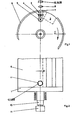
- each plate cylinder 1 having the channel 2 on the drive side and the operating side is either opposite one another or only on one side in succession or adjacent to one another outside of the printing area and
- the precisely fitting openings 7 preferably have the shape of a circular punched punch, which appears as a light mark. However, oval shapes, rectangular, square or triangular shapes are also suitable.
- This light mark which is generated synchronously with the rotation of the plate cylinder 1, is projected through a fixedly mounted optical system 8 in the optimal scale onto a machine-mounted digitally position-sensitive line photosensor 12 in the dark environment when the preferably circular die cut (7) runs through it.
- a current transformer 10 and a pulse generator 11 with an additional trigger pulse.
- the optics 8 serve to adapt the geometry of the precisely fitting opening 7 to the dimensions of suitable commercially available light receivers having a large number of photosensitive elements.
- the light marks formed by the precisely fitting openings 7 are adapted to the grid of the light receivers in an optimal, finely graded gradation.
- the following display can already be adapted to a common scaling during the measurement.
- a line photosensor has line-shaped photosensitive areas with e.g. well over 1,000 photosensitive elements, also known as CCD line imaging IC.
- Illumination device 3, 4, 5 and line photo sensor 12 with upstream optics 8 can change their opposite position, so that each light transmitter or light receiver arranged in a breakthrough in the jacket of the plate cylinder rotate with the plate cylinder 1, while the non-rotating assembly is arranged in a machine-fixed manner.
- the measuring points of the individual plate cylinders 1 pass through the sensors assigned to them in a machine-related, special machine position. Deviations after plus or minus are a measure of the registration error. Using the remote register adjustment, all plate cylinders 1 can be set to "zero" or a zero deviation that is the same for all plate cylinders 1.
- the pulse generator 11 delivers counting pulses which are evenly distributed over the circumference and which are passed via a gate circuit 15 to a counter 16 and a preselection counter 33.
- the pulse generator 11 delivers a single pulse per revolution, hereinafter referred to as a zero pulse. This is e.g. mechanically adjusted so that it is triggered at a time when the nominal start of pressure of the plate cylinder 1 to be adjusted passes the position of the line photo sensor 12. Other reference points of the measurement are also possible.
- the leading edge of the zero pulse is generated in a pulse shaper 32 (FIG. 5) to form a signal of a short duration that is independent of the machine speed. It resets the counter 16 and the preselection counter 33 to the zero position and an electronic switch 34 to the basic position.
- a new measuring cycle is now prepared. This starts when a timer 14, controlled by the zero pulse, opens the gate circuit 15 with a signal with a slight offset in time and switches a memory 24 to "ready for storage". The counting pulses thus arrive from the pulse generator 11, the counter 16 and the preselection counter 33 in order to be added there.
- the gate circuit 15 is closed by a signal triggered by a peak level indicator 50. This is prepared when the input signal, starting from an OR link 25, has exceeded the set level of a threshold switch 50A (FIG. 6). The signal which is still rising is now also fed to a peak value memory 50B, which stores the still rising maximum level with a low loss rate and applies the stored signal to an input of a compensator 50C. At the second input of the compensator 50C is the level emanating from the OR link 25. This level is only reduced when the line photo sensor 12 receives slightly less light through the rotating, precisely fitting opening 7. As a result of the voltage difference then present at the inputs of the compensator 50C, the pulse emanating from the assembly 50 (FIG. 6) is triggered and closes the gate circuit 15.
- the counter reading obtained in this way is a measure of the path that the circumference of the plate cylinder 1 has covered the specified setting from the nominal start of pressure to the precisely fitting opening 7.
- the peak level indicator 50 is actuated by the line photo sensor 12 when the precisely fitting opening 7 illuminated by the light source 5 is moved past.
- the interposed OR link 25 connects the individual sensors of the line photo sensor 12 to the common input at the peak level indicator 50.
- the individual elements themselves are controlled and forwarded with digital signals via a clock generator 17 and clock 27. These signals are also fed to the memory 24, which was switched to readiness for takeover by the output signal of the timing element 14.
- the store command is provided by an AND link 35 if the electronic switch 34 has previously been reset by the zero pulse and activates one input, while the second input from the peak level indicator 50 is controlled.
- the position of that individual sensor of the line photo sensor 12 which has responded to the rotating, illuminated, precisely fitting opening 7 is thus stored in the memory 24.
- This position is fed to a display 19 and a comparator 30 or the like - if necessary via a code converter 26 - and is displayed or compared with a target value. Differences between the setpoint and actual value serve, interruptable by an automatic off switch 48, in an output circuit 31 to form the control signals for the axial adjustment 58, 59 of the plate cylinder 1 to the left or right.
- the target value for the printing unit to be controlled is entered by means of a target value setting 28 and fed to the comparator 30 via a reference variable selector switch 29.
- the command variable selector switch 29 also allows the command variable to be specified for another printing unit and thus to drive the machine to the same page register.
- the status of the counter 16 is activated, if necessary, via a code converter 18, a display 9 and the comparator 22.
- the takeover into the memory of the display 9, as well as the display 19, is triggered by a timer 54 with a slight delay due to the output of the peak level indicator 50.
- the functions of setpoint adjustment 20, reference variable selector switch 21, comparator 22 and automatic off switch 47 correspond to those of function groups 28, 29, 30 and 48 for the lateral adjustment.
- the output circuit 23 supplies signals which move the plate cylinder 1 back and forth in the circumferential direction 56, 57 relative to the drive.
- the presetting of the preselection counter 33 is expediently to be selected such that the coincidence between this and the counter reading occurs when the second, precisely fitting opening 7, which is laterally offset from the first in is located behind the printing plate area and is illuminated by the light source 5B, just before the line photosensor 12.
- the output of the preselection counter 33 sets the electronic changeover switch 34, which as a result switches its output signal from the AND link 35 to an AND link 40 and activates a memory 41 which receives the same position information of the line photo sensor 12 as the memory 24.
- an output pulse of the peak level indicator 50 is now triggered at the AND link 40 that the position information present at the memory 41 is taken over and stored and, if necessary via a code converter 42, leads to a display 44 and a comparator 43.
- An output circuit 45 that can be separated with the automatic-off switch 49 controls the drive of the cylinder inclined position 60, 61 back and forth.
- the automatic cylinder inclination is only activated via an OR link 46 if none of the output circuits 23 and 31 still emit control signals.
- the transfer into the memory of the display 44 is slightly delayed by a timer 55, triggered by the memory signal of the AND link 40.
- the block diagram for the other printing units of a printing press is identical to the above, but with the restriction that further pulse generators 11 can be dispensed with if, according to FIG. 5, a preselection counter 51 to 53 is used for a four-color press for each additional printing unit.
- the number of preselection steps is to be selected so that the signal triggering of the preselection counter takes place when the nominal start of pressure of the plate cylinder 1 to be controlled in each case passes the position of the respective line photo sensor 12.
- the pulse formers 32 of the respective printing unit controls are activated.
- the individual printing units in the components for example 21, 22, 29 and 30, are indicated by arrows.
- the second lateral measurement for the cylinder inclined position provided according to the exemplary embodiment described above is omitted if precisely fitting openings 7 arranged on both sides of the cylinder should be scanned.
- the modules 9, 12, 15, 16, 22, 23, 25 and 50 are then required for the measurement on the opposite side of the pressure plate 6. This means that in this case the pulse shaper 32, the timing element 14, the clock generator 17 with clock 27, the target value setting 20 and the reference variable selector switch 21 can be used together for the cylinder inclination measurement.
- position detectors 13 instead of the line photo sensors 12.
- a position detector works like a potentiometer, to which a current is fed via the tap contact. It is divided into two streams to the end contacts. The difference in the currents corresponds to the position of the tap contact, continuously and with high resolution.
- Position detectors are commercially available in various sizes and housings as single-axis and two-axis position detectors. According to FIG. 7, at the end of the axis of the plate cylinder 1 there are the current transmitter 10 and a pulse generator 11 for generating two trigger pulses 11A and 11B which are independent of one another and can be adjusted to any cylinder angle in the format range.
- the pulse generator 11A is set so that when the plate cylinder 1 is in the zero position for the cylinder drive and in the center position for the pressure cylinder, a trigger signal is triggered when the center of the plate cylinder 1 rotating light source 5A is radially opposite the standing position detector 13.
- the precisely fitting opening 7 is provided in the printing form 6 in the area of the start of the print so that it is also in the center of the lighting device 3, 4, 5 when the plate is optimally mounted.
- the A / D converter 37 in the sample state is switched to "hold” with the pulse generator 11A at the same time as an A / D converter 38 and sends its digitized signal to a memory 39, which delays the takeover signal slightly via the timing element 62 receives.
- the position of the precisely fitting opening 7 stored in the memory 39 is indicated on the circumference with the display 9.
- the corresponding register adjustment can be carried out manually by adjusting the cylinder for the drive in a known manner.
- the content of the memory 39 is also passed to a reference variable selection switch 21, the reference variable selection switches (not shown) of the further printing units of the printing press and to the comparator 22.
- the reference variable selector switch 21 By means of the reference variable selector switch 21, either the actual value of each printing unit or a signal level which is the same for all printing units and is generated by the reference signal generator 63 and which suitably corresponds to the basic printing plate setting can be specified.
- the setpoint / actual value comparison produces a signal which can be interrupted by the automatic off switch 47 and which in the output circuit 23 gives corrective control pulses to the circumferential adjustment of the plate cylinder 1 in accordance with the measured plate circumferential position which deviates from the nominal value.
- the A / D converter with sample and hold 38, the memory 66, the display 19, the reference variable selection switch 29, the comparator 30, the automatic off switch 48 and the output circuit 31 is carried out in the same way as described above for the measurement and display of the lateral plate positions and, if required, the lateral cylinder adjustment.
- the A / D converters 37 and 38 are reset to the sample function with a slight delay via the timing element 71 and thus for a new conversion prepared.
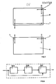
- the second registration punch is laterally offset in the circumferential direction at the end of the plate format outside the inking area (see FIG. 3).
- the second lighting device 3, 4, 5 with the light source 5B is also located in the plate cylinder 1.
- the pulse generator 11B is set in such a way that the signal is triggered at the point in time at which the center of the light source 5B, when the plate cylinder 1 is in the zero position for driving and its center position in relation to the printing cylinder, is radially opposite the standing position detector 13.
- An A / D converter with sample and hold 64 is thus switched to "hold” with the analog signal currently coming from amplifier 65 and the A / D conversion is carried out.
- the digitized signal is stored in the memory 68 and displayed by means of the display 44. Then, slightly delayed by the timer 69, the A / D converter 64 is reset to the sample function and thus prepared for the following measurement cycle.
- the comparator 43 receives its actual value from the memory 68, its setpoint, as does the comparator 30, from the reference variable selection switch 29 controls, can be switched off by the automatic off switch 49, the output circuit 45, which in turn switches on the inclined cylinder adjustment for register correction according to the measured values. This is blocked by an OR link 70 if an actuating signal is still emitted by one or both output circuits 23 and / or 31.
- the precisely fitting openings 7 and the corresponding lighting devices 3, 4, 5, the plate cylinder 1 can also be measured on both sides.
- a further, one-dimensional position detector 13 is necessary to form a two-dimensional position detector 13.
- An example with suitable locations of the punched punch is again shown in FIG. 3.
- the block diagram described above has to be modified in some points.
- the pulse generator 11B is omitted.
- an additional amplifier, not shown, is necessary, the signals of which are further processed via a corresponding assembly chain 43, 44, 45, 49, 64, 68. All A / D converters and memories are controlled in parallel by the pulse generator 11A and the downstream timing elements.
- the comparator 43 receives its reference variable from the reference variable selection switch 21. With the impluser 11B, the timing elements 67 and 69 are omitted.
- a position detector of a different type is the four-quadrant position detector 72 shown in FIG. 9. Its mostly round, light-sensitive surface consists of four sector-shaped individual sensors 73 with a small mutual space, the tips of which meet centrally in the middle and cross-like by means of electrically insulating dividing lines 74 are separated. With it it can be determined on which of the four sectors the predominantly punctiform light mark 75 hits without precise location determination. This is only possible in the center because all four individual sensors 73 can be illuminated equally by a light mark 75 that strikes at this point and the sum of all output signals thus becomes zero.
- An evaluation circuit using the example of a circumferential measuring channel is shown in FIG. 8.
- the signals of the two diametrically opposed sectors of the four-quadrant position detector 72 are fed to the comparators 78 and 79 after amplification by the amplifiers 76 and 77.
- the comparator 79 is provided with a narrow tolerance field. Its output to the memory 80 determines whether and in which direction there is a registration error.
- the optical or acoustic displays 81 and 82 are activated or the control signals of the output circuit 84, which can be separated with the automatic off switch 83, are activated for adjusting the plate cylinder. They consist of pulses that become more intense when the comparator 78 has been driven by a larger input voltage difference.
- the output signals of the comparator 78 for pulse intensity control of the output circuit 84 and of the comparator 79 for triggering the directional pulses on the same output circuit are taken over when a pulse generator 85 is triggered with a trigger pulse.
- the trigger is set according to the procedure previously described.
- the circuit shown should also be used to adjust the sides and diagonal bends.
- one of the position detectors 72 can be replaced by a one-dimensional system, a duo sensor. With him, the measurement is made on the straight, isolated dividing line between the two, mostly right angle sensor elements.
- the movement of the actuator is stopped without a precise position determination having been necessary beforehand when the ratio of the illuminated sensor areas, which is determined by measuring the outputs a, a 'or b, b', is equal to 1 or the difference is equal Is 0.
- the output signals of the output circuit can have an electromechanical switch (relay or contactor) or an electronic switching device (e.g. semiconductor relay, thyristor, etc.) for switching a motor for clockwise or counterclockwise rotation, but also be used to switch on solenoid valves with hydraulic or pneumatic register adjustment.
- an electromechanical switch relay or contactor
- an electronic switching device e.g. semiconductor relay, thyristor, etc.
Landscapes
- Engineering & Computer Science (AREA)
- Mechanical Engineering (AREA)
- Inking, Control Or Cleaning Of Printing Machines (AREA)
- Rotary Presses (AREA)
- Length Measuring Devices By Optical Means (AREA)
- Registering Or Overturning Sheets (AREA)
- Automobile Manufacture Line, Endless Track Vehicle, Trailer (AREA)
- Body Structure For Vehicles (AREA)
- Printing Methods (AREA)
- Supply, Installation And Extraction Of Printed Sheets Or Plates (AREA)
Priority Applications (1)
| Application Number | Priority Date | Filing Date | Title |
|---|---|---|---|
| AT87107861T ATE67122T1 (de) | 1986-06-14 | 1987-05-30 | Einrichtung an druckmaschinen mit stelleinrichtungen fuer umfangs-, seiten- und diagonalregister. |
Applications Claiming Priority (6)
| Application Number | Priority Date | Filing Date | Title |
|---|---|---|---|
| DE3620139 | 1986-06-14 | ||
| DE3620138 | 1986-06-14 | ||
| DE3620138 | 1986-06-14 | ||
| DE3620139 | 1986-06-14 | ||
| DE3703998 | 1987-02-10 | ||
| DE19873703998 DE3703998A1 (de) | 1986-06-14 | 1987-02-10 | Einrichtung an druckmaschinen mit stelleinrichtungen fuer umfangs-, seiten- und diagonalregister |
Publications (3)
| Publication Number | Publication Date |
|---|---|
| EP0249788A2 true EP0249788A2 (fr) | 1987-12-23 |
| EP0249788A3 EP0249788A3 (en) | 1989-10-25 |
| EP0249788B1 EP0249788B1 (fr) | 1991-09-11 |
Family
ID=27194495
Family Applications (1)
| Application Number | Title | Priority Date | Filing Date |
|---|---|---|---|
| EP87107861A Expired - Lifetime EP0249788B1 (fr) | 1986-06-14 | 1987-05-30 | Dispositif de machines d'impression comportant des dispositif de réglage du registre longitudinal, transversal et diagonal |
Country Status (4)
| Country | Link |
|---|---|
| EP (1) | EP0249788B1 (fr) |
| JP (1) | JPH0667618B2 (fr) |
| AT (1) | ATE67122T1 (fr) |
| DE (1) | DE3772857D1 (fr) |
Cited By (3)
| Publication number | Priority date | Publication date | Assignee | Title |
|---|---|---|---|---|
| FR2651721A1 (fr) * | 1989-09-14 | 1991-03-15 | Heidelberger Druckmasch Ag | Dispositif de mesure dans une machine rotative d'impression. |
| EP0456006A1 (fr) * | 1990-05-08 | 1991-11-13 | Heidelberger Druckmaschinen Aktiengesellschaft | Méthode et arrangement pour la recherche de fautes de repérage sur un produit imprimé muni de marques de repérages |
| CN102454954A (zh) * | 2010-10-29 | 2012-05-16 | 鸿骐新技股份有限公司 | 适用于基板的高速视觉定位装置及其方法 |
Family Cites Families (8)
| Publication number | Priority date | Publication date | Assignee | Title |
|---|---|---|---|---|
| GB544830A (en) * | 1940-02-27 | 1942-04-29 | Champlain Corp | Improvements in or relating to register control apparatus for maintaining the operation of a rotating element on a travelling web in register with any prior conditioningof said web |
| US2448292A (en) * | 1943-10-22 | 1948-08-31 | Cottrell C B & Sons Co | Geared adjustment means |
| FR1036401A (fr) * | 1950-05-02 | 1953-09-08 | Licentia Gmbh | Dispositif pour la détermination de la position relative des images ou des repèresd'impression sur des bandes de papier ou d'étoffe |
| JPS5814752A (ja) * | 1981-07-21 | 1983-01-27 | Komori Printing Mach Co Ltd | 多色印刷機の見当自動調整装置 |
| DE3136703C1 (de) * | 1981-09-16 | 1982-11-04 | M.A.N.- Roland Druckmaschinen AG, 6050 Offenbach | Einrichtungen an Druckmaschinen mit Registerverstelleinrichtungen |
| DE3302200A1 (de) * | 1982-01-25 | 1983-08-04 | Dai Nippon Insatsu K.K., Tokyo | Verfahren zum einrichten einer offset-druckpresse und vorrichtungen zur durchfuehrung des verfahrens |
| DD227095A1 (de) * | 1984-10-05 | 1985-09-11 | Polygraph Leipzig | Einrichtung zur registerkontrolle und -verstellung |
| US4680806A (en) * | 1984-12-04 | 1987-07-14 | Koenig & Bauer Aktiengesellschaft | Edge location measuring head |
-
1987
- 1987-05-30 AT AT87107861T patent/ATE67122T1/de not_active IP Right Cessation
- 1987-05-30 EP EP87107861A patent/EP0249788B1/fr not_active Expired - Lifetime
- 1987-05-30 DE DE8787107861T patent/DE3772857D1/de not_active Expired - Lifetime
- 1987-06-15 JP JP62147189A patent/JPH0667618B2/ja not_active Expired - Lifetime
Cited By (4)
| Publication number | Priority date | Publication date | Assignee | Title |
|---|---|---|---|---|
| FR2651721A1 (fr) * | 1989-09-14 | 1991-03-15 | Heidelberger Druckmasch Ag | Dispositif de mesure dans une machine rotative d'impression. |
| EP0456006A1 (fr) * | 1990-05-08 | 1991-11-13 | Heidelberger Druckmaschinen Aktiengesellschaft | Méthode et arrangement pour la recherche de fautes de repérage sur un produit imprimé muni de marques de repérages |
| CN102454954A (zh) * | 2010-10-29 | 2012-05-16 | 鸿骐新技股份有限公司 | 适用于基板的高速视觉定位装置及其方法 |
| CN102454954B (zh) * | 2010-10-29 | 2013-07-17 | 鸿骐新技股份有限公司 | 适用于基板的高速视觉定位装置及其方法 |
Also Published As
| Publication number | Publication date |
|---|---|
| DE3772857D1 (de) | 1991-10-17 |
| JPH0667618B2 (ja) | 1994-08-31 |
| ATE67122T1 (de) | 1991-09-15 |
| EP0249788B1 (fr) | 1991-09-11 |
| EP0249788A3 (en) | 1989-10-25 |
| JPS62299340A (ja) | 1987-12-26 |
Similar Documents
| Publication | Publication Date | Title |
|---|---|---|
| DE3703998A1 (de) | Einrichtung an druckmaschinen mit stelleinrichtungen fuer umfangs-, seiten- und diagonalregister | |
| EP0241773B1 (fr) | Détermination des défauts de repérage dans l'impression polychrome | |
| EP0126211B1 (fr) | Dispositif incrémental de mesure de longueurs ou d'angles | |
| US4089264A (en) | Inking unit for printing machines | |
| DE3789847T2 (de) | Vorrichtung zum Zuführen und Überwachen von Streifen. | |
| DE3836310C2 (de) | Verfahren zum Einstellen einer Wendeeinrichtung an einer Druckmaschine mit mehreren Druckwerken | |
| CH657318A5 (de) | Vorrichtung zur verkuerzung von einrichtezeiten an druckmaschinen mit registerverstelleinrichtungen. | |
| DE1031529B (de) | Beruehrungsloses Breitenmessgeraet | |
| EP0023299A1 (fr) | Procédé et dispositif pour ajuster le registre de machines à imprimer en creux | |
| DE4106210A1 (de) | Laser-markierungseinrichtung | |
| DE2322194C2 (de) | Einrichtung zum Anlegen eines Bogens | |
| DE1803925C3 (de) | Steuereinrichtung eines Vervielfältigungsgerätes | |
| EP1843898B2 (fr) | Procede de reperage | |
| EP0249788B1 (fr) | Dispositif de machines d'impression comportant des dispositif de réglage du registre longitudinal, transversal et diagonal | |
| DE68917406T2 (de) | Individuelle Antriebsvorrichtung für Druckeinheiten. | |
| DE2901980A1 (de) | Einrichtung zur steuerung einer druckmaschine | |
| DE1001747B (de) | Verfahren zur Regelung der Registerhaltigkeit einer laufenden Bahn, an der ein oder mehrere Arbeitsgaenge auszufuehren sind | |
| DE2044663B2 (de) | Vorrichtung zum Ablesen von Marken auf der Druckform einer Offsetdruckmaschine | |
| DE2446435C2 (de) | Schaltungsanordnung für die Einstellung der Intensität mehrerer in einer Bildreproduktionseinrichtung zur gerasterten Reproduktion nebeneinander angeordneter Lichtquellen | |
| DE3909764C2 (fr) | ||
| EP0726146A2 (fr) | Dispositif de commande pour une machine à imprimer | |
| DE2557944B2 (de) | Anordnung zur Erzeugung von Austastsignalen für die Registerregelung | |
| DE2505380A1 (de) | Digitale vorrichtung zur stillsetzung des stempels von exzenterpressen, schneid- und nibbelmaschinen im bereich des oberen totpunktes | |
| DE2349073C3 (de) | Elektrische Kopiersteuerungsvorrichtung mit einem fotoelektrisch einen Linienzug oder eine Kante abtastenden Abtastkopf | |
| DE1163436B (de) | Verfahren und Vorrichtung zum automatischen Einstellen eines Maschinenteils |
Legal Events
| Date | Code | Title | Description |
|---|---|---|---|
| PUAI | Public reference made under article 153(3) epc to a published international application that has entered the european phase |
Free format text: ORIGINAL CODE: 0009012 |
|
| AK | Designated contracting states |
Kind code of ref document: A2 Designated state(s): AT CH DE FR GB IT LI NL SE |
|
| PUAL | Search report despatched |
Free format text: ORIGINAL CODE: 0009013 |
|
| AK | Designated contracting states |
Kind code of ref document: A3 Designated state(s): AT CH DE FR GB IT LI NL SE |
|
| 17P | Request for examination filed |
Effective date: 19890922 |
|
| 17Q | First examination report despatched |
Effective date: 19910211 |
|
| ITF | It: translation for a ep patent filed | ||
| GRAA | (expected) grant |
Free format text: ORIGINAL CODE: 0009210 |
|
| AK | Designated contracting states |
Kind code of ref document: B1 Designated state(s): AT CH DE FR GB IT LI NL SE |
|
| REF | Corresponds to: |
Ref document number: 67122 Country of ref document: AT Date of ref document: 19910915 Kind code of ref document: T |
|
| REF | Corresponds to: |
Ref document number: 3772857 Country of ref document: DE Date of ref document: 19911017 |
|
| ET | Fr: translation filed | ||
| GBT | Gb: translation of ep patent filed (gb section 77(6)(a)/1977) | ||
| PLBE | No opposition filed within time limit |
Free format text: ORIGINAL CODE: 0009261 |
|
| STAA | Information on the status of an ep patent application or granted ep patent |
Free format text: STATUS: NO OPPOSITION FILED WITHIN TIME LIMIT |
|
| 26N | No opposition filed | ||
| EAL | Se: european patent in force in sweden |
Ref document number: 87107861.4 |
|
| PGFP | Annual fee paid to national office [announced via postgrant information from national office to epo] |
Ref country code: CH Payment date: 19950418 Year of fee payment: 9 |
|
| PGFP | Annual fee paid to national office [announced via postgrant information from national office to epo] |
Ref country code: GB Payment date: 19950419 Year of fee payment: 9 |
|
| PGFP | Annual fee paid to national office [announced via postgrant information from national office to epo] |
Ref country code: FR Payment date: 19950420 Year of fee payment: 9 |
|
| PGFP | Annual fee paid to national office [announced via postgrant information from national office to epo] |
Ref country code: SE Payment date: 19950424 Year of fee payment: 9 |
|
| PGFP | Annual fee paid to national office [announced via postgrant information from national office to epo] |
Ref country code: AT Payment date: 19950426 Year of fee payment: 9 |
|
| PGFP | Annual fee paid to national office [announced via postgrant information from national office to epo] |
Ref country code: NL Payment date: 19950531 Year of fee payment: 9 |
|
| PG25 | Lapsed in a contracting state [announced via postgrant information from national office to epo] |
Ref country code: GB Effective date: 19960530 Ref country code: AT Effective date: 19960530 |
|
| PG25 | Lapsed in a contracting state [announced via postgrant information from national office to epo] |
Ref country code: SE Effective date: 19960531 Ref country code: LI Effective date: 19960531 Ref country code: CH Effective date: 19960531 |
|
| PG25 | Lapsed in a contracting state [announced via postgrant information from national office to epo] |
Ref country code: NL Effective date: 19961201 |
|
| REG | Reference to a national code |
Ref country code: CH Ref legal event code: PL |
|
| GBPC | Gb: european patent ceased through non-payment of renewal fee |
Effective date: 19960530 |
|
| PG25 | Lapsed in a contracting state [announced via postgrant information from national office to epo] |
Ref country code: FR Effective date: 19970131 |
|
| EUG | Se: european patent has lapsed |
Ref document number: 87107861.4 |
|
| NLV4 | Nl: lapsed or anulled due to non-payment of the annual fee |
Effective date: 19961201 |
|
| REG | Reference to a national code |
Ref country code: FR Ref legal event code: ST |
|
| PGFP | Annual fee paid to national office [announced via postgrant information from national office to epo] |
Ref country code: DE Payment date: 19980420 Year of fee payment: 12 |
|
| PG25 | Lapsed in a contracting state [announced via postgrant information from national office to epo] |
Ref country code: DE Free format text: LAPSE BECAUSE OF NON-PAYMENT OF DUE FEES Effective date: 20000301 |
|
| PG25 | Lapsed in a contracting state [announced via postgrant information from national office to epo] |
Ref country code: IT Free format text: LAPSE BECAUSE OF NON-PAYMENT OF DUE FEES;WARNING: LAPSES OF ITALIAN PATENTS WITH EFFECTIVE DATE BEFORE 2007 MAY HAVE OCCURRED AT ANY TIME BEFORE 2007. THE CORRECT EFFECTIVE DATE MAY BE DIFFERENT FROM THE ONE RECORDED. Effective date: 20050530 |