EP0250733A2 - Machine pour bourrer de produits pâteux en particulier des saucisses - Google Patents
Machine pour bourrer de produits pâteux en particulier des saucisses Download PDFInfo
- Publication number
- EP0250733A2 EP0250733A2 EP87105298A EP87105298A EP0250733A2 EP 0250733 A2 EP0250733 A2 EP 0250733A2 EP 87105298 A EP87105298 A EP 87105298A EP 87105298 A EP87105298 A EP 87105298A EP 0250733 A2 EP0250733 A2 EP 0250733A2
- Authority
- EP
- European Patent Office
- Prior art keywords
- filling
- pump
- machine according
- gear
- motor
- Prior art date
- Legal status (The legal status is an assumption and is not a legal conclusion. Google has not performed a legal analysis and makes no representation as to the accuracy of the status listed.)
- Granted
Links
- 235000013580 sausages Nutrition 0.000 title claims abstract description 49
- 235000013372 meat Nutrition 0.000 claims abstract description 5
- 238000012937 correction Methods 0.000 claims description 18
- 230000015654 memory Effects 0.000 claims description 17
- 230000005540 biological transmission Effects 0.000 claims description 12
- 238000011144 upstream manufacturing Methods 0.000 claims description 8
- 238000004519 manufacturing process Methods 0.000 claims description 7
- 239000000463 material Substances 0.000 claims description 7
- 238000012544 monitoring process Methods 0.000 claims description 4
- 230000015572 biosynthetic process Effects 0.000 claims description 3
- 235000011837 pasties Nutrition 0.000 claims 1
- 230000006870 function Effects 0.000 description 5
- 238000000034 method Methods 0.000 description 5
- 238000005457 optimization Methods 0.000 description 5
- 230000008569 process Effects 0.000 description 5
- QAWIHIJWNYOLBE-OKKQSCSOSA-N acivicin Chemical compound OC(=O)[C@@H](N)[C@@H]1CC(Cl)=NO1 QAWIHIJWNYOLBE-OKKQSCSOSA-N 0.000 description 4
- 230000008859 change Effects 0.000 description 3
- 238000011161 development Methods 0.000 description 3
- 238000010586 diagram Methods 0.000 description 3
- 238000003825 pressing Methods 0.000 description 3
- 238000012545 processing Methods 0.000 description 3
- 238000003860 storage Methods 0.000 description 3
- 101100390736 Danio rerio fign gene Proteins 0.000 description 2
- 101000584583 Homo sapiens Receptor activity-modifying protein 1 Proteins 0.000 description 2
- 101000584590 Homo sapiens Receptor activity-modifying protein 2 Proteins 0.000 description 2
- 101100390738 Mus musculus Fign gene Proteins 0.000 description 2
- 102100030697 Receptor activity-modifying protein 1 Human genes 0.000 description 2
- 102100030696 Receptor activity-modifying protein 2 Human genes 0.000 description 2
- 230000008878 coupling Effects 0.000 description 2
- 238000010168 coupling process Methods 0.000 description 2
- 238000005859 coupling reaction Methods 0.000 description 2
- 238000011156 evaluation Methods 0.000 description 2
- 239000002184 metal Substances 0.000 description 2
- 238000004806 packaging method and process Methods 0.000 description 2
- 230000001360 synchronised effect Effects 0.000 description 2
- 238000005303 weighing Methods 0.000 description 2
- 208000019300 CLIPPERS Diseases 0.000 description 1
- 241001237745 Salamis Species 0.000 description 1
- 230000001133 acceleration Effects 0.000 description 1
- 235000013351 cheese Nutrition 0.000 description 1
- 208000021930 chronic lymphocytic inflammation with pontine perivascular enhancement responsive to steroids Diseases 0.000 description 1
- 238000004140 cleaning Methods 0.000 description 1
- 239000006071 cream Substances 0.000 description 1
- 230000002349 favourable effect Effects 0.000 description 1
- 235000013305 food Nutrition 0.000 description 1
- 230000003993 interaction Effects 0.000 description 1
- 238000005259 measurement Methods 0.000 description 1
- 239000005022 packaging material Substances 0.000 description 1
- 230000002093 peripheral effect Effects 0.000 description 1
- 230000009467 reduction Effects 0.000 description 1
- 230000000717 retained effect Effects 0.000 description 1
- 235000015175 salami Nutrition 0.000 description 1
- 238000005070 sampling Methods 0.000 description 1
- 230000001629 suppression Effects 0.000 description 1
- 238000004804 winding Methods 0.000 description 1
Images


Classifications
-
- A—HUMAN NECESSITIES
- A22—BUTCHERING; MEAT TREATMENT; PROCESSING POULTRY OR FISH
- A22C—PROCESSING MEAT, POULTRY, OR FISH
- A22C11/00—Sausage making ; Apparatus for handling or conveying sausage products during manufacture
- A22C11/02—Sausage filling or stuffing machines
Definitions
- the invention relates to a machine for filling doughy media, in particular sausage meat, into a tubular casing, with a filling pump, the pressure side of which is connected in terms of flow to a filling tube which accommodates the gathered sausage casing, the casing being emitted by the escaping medium between a brake ring and the free one Filling tube end is pulled off.
- Such machines are very common, particularly in the food processing industry, and they are used there for the production of sausages but also for filling portions of cream cheese and the like. Two main requirements are placed on these machines, namely on the one hand high portion performance and on the other hand great portion weight accuracy.
- the object of the invention is therefore to further develop a machine of the type mentioned at the outset in such a way that the number of portions per unit of time and, if possible, the portion accuracy can be increased.
- the machine is designed according to the preamble of claim 1 in accordance with the characterizing part of this claim.
- an electrically controllable motor in particular a so-called magnetic rotor
- the drive can be simplified on the one hand and a higher portion speed can be achieved on the other hand by starting and stopping or slowing down and accelerating such motors up to 400 times per minute. The latter is necessary if the clip setting or turning off is provided when the pump is stopped or braked. Because such a motor can be easily controlled via a microprocessor and the latter is known to work with extreme accuracy, the portioning accuracy can also be increased in this way.
- the pump as a gear pump with an internally toothed, drivable outer wheel and thus meshing, externally toothed, eccentrically mounted to the outer gear pinion.
- Pumps of this type are used as feed pumps, in particular in the sausage processing industry. They are characterized by high reliability and robustness. In addition, they are also equipped with a one- or two-part pressure piece, which separates the pressure side from the suction side. A more detailed explanation is, however, not necessary because, as I said, they are known pumps, at least as far as the working principle is concerned.
- a further embodiment of the invention is characterized in that the filled sausage strand running off can be subdivided into individual sausages by means of a controllable clip device, in particular at equal and preferably adjustable intervals, when the pump drive is switched off.
- a controllable clip device in particular at equal and preferably adjustable intervals, when the pump drive is switched off.
- Clips are, for example, U-shaped metal clips, which are pushed over the constriction point between adjacent corners and then deformed into a ring or a wire winding. If you place two such clips next to each other at a short distance, you can cut the sausage casing between these two clips and get individual sausages in this way.
- the filling tube can be rotated by at least about one turn to form a tip by means of a twisting device.
- the filling tube can be rotated by at least about one turn to form a tip by means of a twisting device.
- the brake ring To the gathered sausage casing and the brake ring are rotated along with the filling tube.
- a pinch point is created just behind the free end of the filling tube.
- Each turn-off process results in a finished sausage and the first tip of the sausage to be filled afterwards.
- the turning of the filled sausage skein or the previously made sausages does not require any special devices, rather the weight and the friction are at least essentially sufficient to prevent rotation.
- the controllable motor is advantageously connected to the drive shaft of the pump outer wheel by means of at least one gear, in particular a toothed belt gear.
- a toothed belt transmission creates a large ratio with high precision in a small footprint.
- a particularly preferred embodiment of the invention provides that a pulse generator for at least the pump control can be driven by means of the pump drive shaft or an upstream transmission shaft.
- a pulse generator for at least the pump control can be driven by means of the pump drive shaft or an upstream transmission shaft.
- the use of a pulse generator is the prerequisite for the precise electronic control and also the possibility of programming this machine. If you drive the pulse generator via the pump drive shaft or in particular an upstream transmission shaft, you save yourself a separate drive and at the same time achieve the synchronous mode of operation in a simple manner.
- the pump drive shaft or gear shaft must run at a predetermined speed. This does not necessarily correspond to the required speed of the pulse generator and is also not provided in the exemplary embodiment. Therefore, a further development of the invention provides that the pulse generator is in drive connection with the pump drive shaft or the transmission shaft via a gear, in particular a further belt or toothed belt gear. This gearbox also ensures the necessary precision. It remains to be noted, however, that another gear, in particular a reduction gear, can be connected between the toothed belt gear and the driven pinion of the pump, and is preferably also provided, the drive for the pulse generator also being able to be derived from a shaft of this additional gear . becomes.
- the pump drive shaft or the upstream transmission shaft is a drive element of a drive of a conveying element in a filling container placed in front of the pump inlet. If there is a comparatively thin and possibly still fat-rich mass in the latter, then it flows from the filling container into the pump inlet located thereon solely on account of its own weight and its flowability. However, if relatively stiff masses have to be portioned, for example in the production of salami, it is necessary at the high output speed to convey this mass to the pump inlet. This is done both formally on the filling container and on the goods to be conveyed fitted conveyor. It is a rotating conveyor element and this can advantageously also be driven synchronously by the controllable motor mentioned. Any necessary adjustment of the speed can easily be achieved by another gear.
- a further variant of the invention is characterized in that the conveying element can be driven by means of a gear wheel or ring gear, which meshes with a pinion which can be driven by the pump shaft or the upstream gear shaft. If necessary, you can put a coupling between them. This is particularly advantageous if the container is to be removed from the pump or at least the pump fill opening for cleaning purposes.
- the electrical control comprises a microcomputer consisting of a microprocessor, memories and input / output components, which consists of the impulses of the pulse generator, which indicate a certain fill weight quantity per pulse and the target weight quantity of the portion to be filled as well as from the physical data of the filling material and the filling material and from the predetermined working speed, a first operating voltage ramp for the first motor that drives the filling pump and generates an operating phase voltage ramp for the second motor that controls the calibration or clip device.
- a further advantageous embodiment of the electrical control provides that the correction value can be stored per batch and can be called up from the memory for the production of the first portion of a batch and can be fed to the control.
- the doughy medium to be filled in portions, in particular sausage meat, is preferably introduced into the filling container 1 by means of a suitable charging device, not shown.
- a suitable charging device not shown.
- It expediently has a conical shape and is located above a filling pump 2. More precisely, it is the case that the outlet 3 of the filling container 1 lies above the inlet 4 of the filling pump 2.
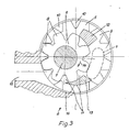
- Essential elements of the filling pump are an internally toothed, drivable outer wheel 5 with drive shaft 7 and an eccentrically arranged, externally toothed pinion 6 with bearing pin 7.
- the pinion teeth 8 engage in the tooth spaces 9 of the outer wheel 5, while the teeth 10 of the outer wheel 5 into the tooth spaces 11 of pinion 6 occur.
- the medium introduced into the pump completely fills the part of the pump interior which is defined by the two pressure pieces or pressure piece parts 12 and 13 and the tooth gaps currently located in the area of these pressure pieces. At the bottom, this space is delimited by a disk-shaped bottom of the outer wheel 5, on which the teeth are perpendicular to the image plane (FIG. 3), while the upper limit is reached by a cover removed in FIG. 3. If you drive the outer wheel 5 in the direction of arrow 14, it takes the pinion 6 in the same direction of rotation.
- the medium is transported to the outlet 15 of the pump via the tooth gaps 11 and 9. There the teeth then alternately enter the tooth gaps and thereby cause the tooth gaps to be emptied into the outlet 15 and an upstream pocket 16 of the housing.
- a filling pipe 17 connects to the outlet 15 of the filling pump 2.
- the front end of the casing 18 in the direction of discharge 20 is suitably closed, for example by a knot. If you now pump the sausage meat or the like into this sausage casing, which is closed at the front, it fills up. It is successively pulled off the filling tube and drained.
- This running, filled sausage strand 21 is constricted at predetermined intervals in the manner explained in more detail below, in order thereby to form sausages in particular of the same length.
- the filling pump 2 is driven intermittently with the aid of an electrically controllable motor 22, in particular a magnetic rotor.
- the motor can be controlled with the aid of a microprocessor, an electrical control device 23.
- the line 24 symbolizes the electrical connection of the control device 23 to the motor 22.
- This second motor 26 can also be driven and controlled via the microprocessor or the electrical control device 23. This symbolizes line 27 in FIG. 2.
- Motor 26 is also a servo motor or a magnetic rotor. The two motors 22 and 26 are thus switched on and off alternately, and one can easily visualize their mode of operation when working quickly, i.e. with a high number of sausages per unit of time, using a sine curve and a superimposed cosine curve (see also FIG. 8).
- the controllable motor or its output shaft 28 is by means of at least one gear 29 - indirectly in the exemplary embodiment - drivingly connected to the pump drive shaft 37.
- the gear 29 is preferably a toothed belt gear with the drive wheel 30 attached to the output shaft 28 and the driven wheel 31 and the toothed belt 32.
- the driven wheel 31 is seated on a gear shaft 33 which carries a pinion 34 of the gear 35. It meshes with a gear 36 on the pump drive shaft 37.
- the gear shaft 33 is guided to the outside via the gear housing and the gear shaft extension 38 carries a drive wheel 39 of a further gear 40, which can also be designed as a belt or toothed belt gear.
- the belt 41 of this gear 40 drives a pinion or wheel 42 which is fastened on a drive shaft of a pulse generator 43.
- This pulse generator is also connected to the electrical control device 23, which is shown schematically in FIG. 1 by the line 44. It provides the necessary impulses to control the drives of the machine and various functions, e.g. Portioning the processor are required.
- the transmission shaft extension 38 is preferably connected to a drive shaft 46 for a conveying element 47 via a releasable coupling 45.
- This is part of a conveying device which forcibly conveys the medium in the filling container 1 to the pump inlet 4.
- the drive shaft 46 contributes to this Purposes at their upper end in FIG. 1 is a pinion 48, the teeth of which mesh with those of a ring gear 49.
- the ring gear is rotatably connected to the conveyor element 47, which passes through it in the axial direction.
- the conveyor element has the shape of a screw conveyor and it is made of a belt-shaped material. The latter was bent into a conical spiral, as FIG. 1 of the drawing clearly shows and which is adapted to the contour of the container.
- the twist-off device 25 is preferably removable. It has a countershaft 50, which is driven intermittently by the second motor 26 according to FIG. 2.
- a first pinion 51 of the countershaft 50 drives, preferably again by means of a belt 52, a gear 53 which is connected to the filling tube 17 in a rotationally fixed manner or is produced in one piece therewith.
- the belt 52 can also be a toothed belt, just like the belt 54, which creates the rotary connection between a second pinion 55 or the like and a second gear 56 or the like. The latter is molded onto or connected to a holder for the brake ring.
- the two ratios 51, 53 and 55, 56 are the same in order to ensure a synchronous turning of the filling tube 17 and the brake ring 19 including the gathered sausage casing 18.
- Control module 63 may be formed, which contains an operating console 57 with a display 59 and a keypad 60 as well as connections 61 for a sample balance and 62 for a logging printer.
- the control module 63 also has slots for receiving a processor card 66, an input / output card 67 and a power supply unit 68, as shown in FIGS. 4 and 5.
- Fig. 6 also shows an arrangement of plugs 69 for connecting the display 59, 70, for connecting the keypad 60 and 71 for connecting a printer and a balance.
- the fuses provided to protect the electrical part are shown at 72.
- the electrical control device 23 the essential element of which is a central control unit (CPU), generates the electrical control signals required for operation, setting and operation. Standard functions that are controlled here are portioning, twisting, operating breaks and a correction of the dosage for the first portion.
- the filling speed can be set via the operating voltage of the first and second servo motors 22 and 26.
- the operating voltage of the servo motors has a ramp-like course in the range from 0 to 10 volts maximum, the value 10 volts corresponding to the maximum filling speed (100%).
- the ramp-shaped operating voltage, called control ramp for short can be in its shape or its course, the consistency of the filling material and the nature of the Packaging material are adapted, the most favorable values being determined empirically and then stored in a read / write memory.
- the electrical control device 23 has a read / write memory 77 in which the portion parameters, such as weight, pause, turning off, turning off delay, filling speed, etc., can be stored for 100 different portions.
- the read / write memory 77 is supplied via an emergency power supply 83, an accumulator, which is located on the processor board, so that the portion data are retained even when the device is switched off or the processor card is pulled out. New portions can be entered or changed using the 6O keypad with a total of 16 keys.
- an information line appears in the 2-digit alphanumeric display, showing the portion number, name and weight of the portions. The desired portion and its data can be called up by entering the portion number.
- two interface sockets 61 and 62 for V 24 and RS 232 interfaces are embedded in the front plate 64 of the control module 63 (FIG. 4), which enable the connection of a sample balance and a printer. Deviations of the samples from the target value are processed to a correction value which is displayed and saved in the portioning parameter "correction".
- the samples are logged by the printer.
- an evaluation of the statistical data of the samples is printed out (setpoint, number, mean, standard deviation, minimum and maximum).
- the date and time are printed out, which are supplied by a clock 82 which is connected to the CPU 73 via the processor bus 75.
- these can be stored on a storage medium after connecting an external memory, preferably a cassette recorder, in the case of a cassette recorder on a cassette.
- the operating voltage of the servo motors with adjustable acceleration and braking ramp as well as the programmable filling speed controls both the filling and the calibration process, the latter of which is initiated by the calibration signal AD (see FIG. 7).
- the operating parameters are entered on two levels, a) filling level and b) system level, both of which are listed below:
- the input parameters are processed accordingly by the electrical control device and lead to the generation of the corresponding output ramp, including a portioning signal P, the calibration signal AD and a speed correction signal V, which is generated whenever the speed, measured via the pulse generator 43, is too high .
- the pulse generator is dimensioned for a wide range of applications and operating states and in the present example is rated at one gram per pulse.
- the twisting or clipping can be set within certain limits so that the desired operating parameters are optimally achieved. This also applies to the correction of the first portion, which is necessary for the following reasons:
- the pump When the machine starts up, i.e. the very first part of the packaging envelope is filled with the doughy medium, the pump must first be filled and only when it is completely filled and the doughy medium has penetrated to the front end of the shirred packaging, a kind of back pressure creates a continuous pump pressure.
- the pump initially works with increasing, ie not constant, pressure. This means that if a certain number of pulses is given for the weight of the portion, a portion that is too light, for example a portion of the first sausage that is too short, is generated.
- FIG. 7 now shows the essential components of the electrical control device 23, consisting of a central control unit (CPU) 73, for example a microprocessor of a known type, the operating processes of which are controlled in time by a clock generator 74.
- the central control unit 73 is connected via a processor bus 75, which comprises the necessary control, address and data lines, to a read / write memory 77, a read memory 78 and a programmable input / output adapter.
- the latter adapter is via an input / output bus 76 with an input / output control 80 and a timer 81 and the keypad 6O.
- the display in turn is connected to the microcomputer via the input / output control 80.
- the clock intended for logging purposes, which specifies the time and date, is connected via the processor bus 75 already mentioned.
- the input / output control 8O has the special task of external control signals, such as the pulses from the pulse generator 43, via the lines 44, the start signal ST or, for example, the data of the sample balance via the connection 61
- the final shape of the exit ramps is largely determined by the material used and the working speed, ie the pro dosing speed of the portions determined and largely determined empirically. These values can be stored, both the read / write memory 77 and the read memory 78, which contains the actual control program, being suitable for this purpose.
Landscapes
- Life Sciences & Earth Sciences (AREA)
- Engineering & Computer Science (AREA)
- Wood Science & Technology (AREA)
- Zoology (AREA)
- Food Science & Technology (AREA)
- Processing Of Meat And Fish (AREA)
- Formation And Processing Of Food Products (AREA)
- Meat, Egg Or Seafood Products (AREA)
- Containers And Plastic Fillers For Packaging (AREA)
- Saccharide Compounds (AREA)
Priority Applications (1)
| Application Number | Priority Date | Filing Date | Title |
|---|---|---|---|
| AT87105298T ATE72504T1 (de) | 1986-05-24 | 1987-04-10 | Maschine zum abfuellen teigiger medien, insbesondere von wurstbraet. |
Applications Claiming Priority (2)
| Application Number | Priority Date | Filing Date | Title |
|---|---|---|---|
| DE3617560 | 1986-05-24 | ||
| DE3617560A DE3617560C2 (de) | 1986-05-24 | 1986-05-24 | Maschine zum Abfüllen teigiger Medien, insbesondere von Wurstbrät |
Publications (4)
| Publication Number | Publication Date |
|---|---|
| EP0250733A2 true EP0250733A2 (fr) | 1988-01-07 |
| EP0250733A3 EP0250733A3 (en) | 1989-04-12 |
| EP0250733B1 EP0250733B1 (fr) | 1992-02-12 |
| EP0250733B2 EP0250733B2 (fr) | 1995-01-25 |
Family
ID=6301602
Family Applications (1)
| Application Number | Title | Priority Date | Filing Date |
|---|---|---|---|
| EP87105298A Expired - Lifetime EP0250733B2 (fr) | 1986-05-24 | 1987-04-10 | Machine pour bourrer de produits pâteux en particulier des saucisses |
Country Status (10)
| Country | Link |
|---|---|
| US (1) | US4823439A (fr) |
| EP (1) | EP0250733B2 (fr) |
| JP (1) | JPS6333206A (fr) |
| AT (1) | ATE72504T1 (fr) |
| CA (1) | CA1265382A (fr) |
| DE (1) | DE3617560C2 (fr) |
| DK (1) | DK260587A (fr) |
| ES (1) | ES2030009T5 (fr) |
| FI (1) | FI87129C (fr) |
| NO (1) | NO169934C (fr) |
Cited By (4)
| Publication number | Priority date | Publication date | Assignee | Title |
|---|---|---|---|---|
| EP0395177A3 (fr) * | 1989-04-28 | 1992-02-26 | HITEC Co., Ltd. | Appareil pour la fabrication de saucisses |
| WO1998017119A1 (fr) * | 1996-10-21 | 1998-04-30 | Townsend Engineering Company | Procede et dispositif pour ligaturer des saucisses |
| EP2407038A1 (fr) | 2010-07-15 | 2012-01-18 | Albert Handtmann Maschinenfabrik GmbH & Co. KG | Dispositif et procédé de refroidissement de machines de produits alimentaires |
| DE102016216851A1 (de) * | 2016-09-06 | 2018-03-08 | Albert Handtmann Maschinenfabrik Gmbh & Co. Kg | Verfahren und Füllmaschine zum Abfüllen eines Lebensmittels |
Families Citing this family (15)
| Publication number | Priority date | Publication date | Assignee | Title |
|---|---|---|---|---|
| IT1223796B (it) * | 1988-09-02 | 1990-09-29 | Cselt Centro Studi Lab Telecom | Dispositivo sfasatore in guida d'onda coassiale |
| JPH0675464B2 (ja) * | 1989-08-04 | 1994-09-28 | プリマハム株式会社 | ソーセージ充填装置 |
| IT220303Z2 (it) * | 1990-11-23 | 1993-09-16 | Righele Giovanni | Dispositivo di azionamento per tramoggia di una pompa rotativa di insacco per carne macinata. |
| ES2131474B1 (es) * | 1997-08-29 | 2000-03-01 | Castro Alejandro Ruiz | Dispositivo de control de un sistema de arrastre para maquinas de atado de embutido. |
| DE29808373U1 (de) | 1998-05-08 | 1999-09-16 | Vemag Maschinen- Und Anlagenbau Gmbh, 27283 Verden | Füllmaschine für Wurstbrät o.dgl. mit einem abklappbaren Vorratsbehälter |
| DE19824829A1 (de) * | 1998-06-04 | 1999-12-23 | Vemag Maschinen & Anlagenbau Gmbh | Verfahren und Einrichtung zur Herstellung portionierter Würste gleicher Längen |
| JP2000332503A (ja) | 1999-05-25 | 2000-11-30 | Sharp Corp | 円偏波発生器 |
| JP3706522B2 (ja) | 2000-02-25 | 2005-10-12 | シャープ株式会社 | 衛星受信用コンバータの導波管装置 |
| EP1479297A1 (fr) * | 2003-05-19 | 2004-11-24 | Borgo & C. S.A.S. Antonio | Trémie d'alimentation pour machines de bourrage pour des pâtes souples et machine de bourrage pour des pâtes souples |
| DE102008033800A1 (de) | 2008-07-18 | 2010-01-28 | Poly-Clip System Gmbh & Co. Kg | Verpackungsvorrichtung und Verfahren zur Steuerung einer Verpackungsvorrichtung |
| CN102342308A (zh) * | 2011-09-20 | 2012-02-08 | 闫树林 | 固定缸和面机刹车装置 |
| JP6232625B2 (ja) | 2013-04-26 | 2017-11-22 | ハイテック株式会社 | 充填装置 |
| NL2012455B1 (en) * | 2014-03-17 | 2016-01-08 | Marel Townsend Further Proc Bv | Method for preparing a casing material used in a co-extruding process of a food product, viscous gelling agent and a method and a system for preparing food products. |
| CN114711275B (zh) * | 2022-04-11 | 2022-12-06 | 重庆市计量质量检测研究院 | 一种一体化香肠灌装设备 |
| EP4275503A1 (fr) * | 2022-05-11 | 2023-11-15 | Poly-clip System GmbH & Co. KG | Machine à clipper pour la fabrication de produits en forme de sauscisses indépendante du réseau d'alimentation éléctrique |
Family Cites Families (10)
| Publication number | Priority date | Publication date | Assignee | Title |
|---|---|---|---|---|
| DE1532010C3 (de) * | 1966-06-30 | 1980-06-26 | Karl Schnell, Maschinenfabrik, 7065 Winterbach | Fördervorrichtung für Zerkleinerungsgut mit einer Förderpumpe und einer Vacuumabsaugeanlage |
| JPS5752243B1 (fr) * | 1971-04-29 | 1982-11-06 | ||
| CH583521A5 (fr) * | 1974-01-22 | 1977-01-14 | Handtmann Albert Fa | |
| DE3018793A1 (de) * | 1980-05-16 | 1981-11-26 | Albert Handtmann Gmbh & Co, 7950 Biberach | Anordnung zum aufeinanderfolgenden portionieren einer fliessfaehigen fuellmasse, insbesondere wurstmasse |
| EP0096378B1 (fr) * | 1982-06-02 | 1986-04-30 | Teepak Produktie N.V. | Procédé et dispositif pour la fabrication automatique de cordons de saucisses |
| IT1163031B (it) * | 1983-01-18 | 1987-04-08 | Effe Di Russo L & C Snc 3 | Sistema per invertire il posizionamento sequenziale dei gruppi operativi nelle macchine automatiche di impacchettamento |
| DE3311567A1 (de) * | 1983-03-30 | 1984-10-04 | Karl 7065 Winterbach Schnell | Maschine zum abfuellen teigiger medien, insbesondere wurstbraet |
| AT381209B (de) * | 1984-10-29 | 1986-09-10 | Nordischer Maschinenbau | Kontinuierlich arbeitende vorrichtung zum aufeinanderfolgenden ausbringen von portionen einer pastoesen masse |
| DE3544448A1 (de) * | 1985-12-16 | 1987-06-19 | Handtmann Albert Maschf | Verfahren und vorrichtung zum abfuellen lufthaltiger, verformbarer massen |
| US4709450A (en) * | 1987-01-13 | 1987-12-01 | Teepak, Inc. | Apparatus and methods of stuffing food casings to provide dimensionally uniform products |
-
1986
- 1986-05-24 DE DE3617560A patent/DE3617560C2/de not_active Expired - Fee Related
-
1987
- 1987-04-10 EP EP87105298A patent/EP0250733B2/fr not_active Expired - Lifetime
- 1987-04-10 AT AT87105298T patent/ATE72504T1/de not_active IP Right Cessation
- 1987-04-10 ES ES87105298T patent/ES2030009T5/es not_active Expired - Lifetime
- 1987-05-22 FI FI872284A patent/FI87129C/fi not_active IP Right Cessation
- 1987-05-22 DK DK260587A patent/DK260587A/da not_active Application Discontinuation
- 1987-05-22 CA CA000537715A patent/CA1265382A/fr not_active Expired - Lifetime
- 1987-05-22 NO NO872162A patent/NO169934C/no not_active IP Right Cessation
- 1987-05-22 US US07/054,268 patent/US4823439A/en not_active Expired - Lifetime
- 1987-05-25 JP JP62126081A patent/JPS6333206A/ja active Pending
Cited By (7)
| Publication number | Priority date | Publication date | Assignee | Title |
|---|---|---|---|---|
| EP0395177A3 (fr) * | 1989-04-28 | 1992-02-26 | HITEC Co., Ltd. | Appareil pour la fabrication de saucisses |
| WO1998017119A1 (fr) * | 1996-10-21 | 1998-04-30 | Townsend Engineering Company | Procede et dispositif pour ligaturer des saucisses |
| AU721788B2 (en) * | 1996-10-21 | 2000-07-13 | Townsend Engineering Company | Sausage encasing machines |
| EP2407038A1 (fr) | 2010-07-15 | 2012-01-18 | Albert Handtmann Maschinenfabrik GmbH & Co. KG | Dispositif et procédé de refroidissement de machines de produits alimentaires |
| DE102010031393A1 (de) | 2010-07-15 | 2012-01-19 | Albert Handtmann Maschinenfabrik Gmbh & Co. Kg | Vorrichtung und Verfahren zur Kühlung von Nahrungsmittelmaschinen |
| DE102010031393B4 (de) * | 2010-07-15 | 2012-07-05 | Albert Handtmann Maschinenfabrik Gmbh & Co. Kg | Vorrichtung und Verfahren zur Kühlung von Nahrungsmittelmaschinen |
| DE102016216851A1 (de) * | 2016-09-06 | 2018-03-08 | Albert Handtmann Maschinenfabrik Gmbh & Co. Kg | Verfahren und Füllmaschine zum Abfüllen eines Lebensmittels |
Also Published As
| Publication number | Publication date |
|---|---|
| FI872284L (fi) | 1987-11-25 |
| CA1265382A (fr) | 1990-02-06 |
| FI872284A0 (fi) | 1987-05-22 |
| DK260587D0 (da) | 1987-05-22 |
| DK260587A (da) | 1987-11-25 |
| NO169934B (no) | 1992-05-18 |
| DE3617560C2 (de) | 1996-08-14 |
| ATE72504T1 (de) | 1992-02-15 |
| JPS6333206A (ja) | 1988-02-12 |
| EP0250733B1 (fr) | 1992-02-12 |
| FI87129C (fi) | 1992-12-10 |
| EP0250733A3 (en) | 1989-04-12 |
| NO169934C (no) | 1992-08-26 |
| EP0250733B2 (fr) | 1995-01-25 |
| DE3617560A1 (de) | 1987-11-26 |
| NO872162L (no) | 1987-11-25 |
| ES2030009T3 (es) | 1992-10-16 |
| NO872162D0 (no) | 1987-05-22 |
| US4823439A (en) | 1989-04-25 |
| ES2030009T5 (es) | 1995-08-16 |
| FI87129B (fi) | 1992-08-31 |
Similar Documents
| Publication | Publication Date | Title |
|---|---|---|
| EP0250733B1 (fr) | Machine pour bourrer de produits pâteux en particulier des saucisses | |
| EP0392083B1 (fr) | Procédé et dispositif pour diviser un chapelet de saucisses formé par une machine de bourrage en saucisses séparées | |
| DE69225728T2 (de) | Verfahren und Vorrichtung zum Aufhängen einer Kette von zusammenhängenden Produkten | |
| EP1902622B1 (fr) | Procédé et dispositif pour diviser un chapelet de saucisses | |
| DE2921427C2 (de) | Vorrichtung zum intermittierenden Ausstoßen einer Wurstmasse oder dergleichen | |
| DE4021305C2 (de) | Vorrichtung zum kontinuierlichen Conchieren von Schokolademasse | |
| EP0439671B1 (fr) | Procédé et dispositif pour la fabrication de saucisses en divisant un chapelet de saucisses | |
| DE2744350A1 (de) | Aufhaengevorrichtung fuer portionierte wurstketten | |
| EP0476258A1 (fr) | Procédé et dispositif pour la fabrication de saucisses | |
| DE1904589C3 (de) | Regelschaltung für eine Anlage zur kontinuierlichen Erzeugung von Polyurethanschaumstoff | |
| DE2402817A1 (de) | Verfahren und vorrichtung zum herstellen von wuersten | |
| DE29880136U1 (de) | Steuerungssystem für Fleischemulsionspumpen in eine Fleischumhüllungsmaschine | |
| EP1082543B1 (fr) | Regulation de la frequence des courses du piston d'une pompe de dosage | |
| WO2001010226A1 (fr) | Ensemble filiere, porte-filiere et dispositif pour extruder des matieres sous forme de pate | |
| EP0621095B1 (fr) | Procédé pour le redressage intermittent de fils | |
| EP1582098B1 (fr) | Procédé et dispositif pour diviser un chapelet de saucisses | |
| DE2856308C2 (de) | Vorrichtung zum dosierten Austragen eines Materials aus einem Vorratsbehälter | |
| EP1421854A1 (fr) | Dispositif avec un remplisseur sous vide et un dispositif de serrage par clip | |
| EP1205110A1 (fr) | Dispositif de mesure de longueurs avec un dispositif de serrage par clip | |
| DE102020123206B3 (de) | Verfahren sowie Vorrichtung zum Abdrehen von schlauchförmigen Hüllen und betreffendes System zum Befüllen schlauchförmiger Hüllen | |
| AT381209B (de) | Kontinuierlich arbeitende vorrichtung zum aufeinanderfolgenden ausbringen von portionen einer pastoesen masse | |
| EP0246667A2 (fr) | Procédé et installation de préparation de produits fourrés | |
| DE19601720A1 (de) | Verfahren zum Betrieb einer Verschließeinrichtung für Verpackungshüllen | |
| EP1312264A1 (fr) | Dispositif de mesure de longeurs avec un dispositif de serrage par clip | |
| DE102008013806A1 (de) | Portioniervorrichtung (Aufwärts Schneiden) |
Legal Events
| Date | Code | Title | Description |
|---|---|---|---|
| PUAI | Public reference made under article 153(3) epc to a published international application that has entered the european phase |
Free format text: ORIGINAL CODE: 0009012 |
|
| AK | Designated contracting states |
Kind code of ref document: A2 Designated state(s): AT BE CH ES FR GB IT LI NL SE |
|
| PUAL | Search report despatched |
Free format text: ORIGINAL CODE: 0009013 |
|
| AK | Designated contracting states |
Kind code of ref document: A3 Designated state(s): AT BE CH ES FR GB IT LI NL SE |
|
| 17P | Request for examination filed |
Effective date: 19890928 |
|
| 17Q | First examination report despatched |
Effective date: 19910104 |
|
| ITF | It: translation for a ep patent filed | ||
| GRAA | (expected) grant |
Free format text: ORIGINAL CODE: 0009210 |
|
| AK | Designated contracting states |
Kind code of ref document: B1 Designated state(s): AT BE CH ES FR GB IT LI NL SE |
|
| REF | Corresponds to: |
Ref document number: 72504 Country of ref document: AT Date of ref document: 19920215 Kind code of ref document: T |
|
| GBT | Gb: translation of ep patent filed (gb section 77(6)(a)/1977) | ||
| ET | Fr: translation filed | ||
| PLBI | Opposition filed |
Free format text: ORIGINAL CODE: 0009260 |
|
| PLBI | Opposition filed |
Free format text: ORIGINAL CODE: 0009260 |
|
| 26 | Opposition filed |
Opponent name: HOEGGER ALPINA AG Effective date: 19921110 |
|
| 26 | Opposition filed |
Opponent name: VEMAG MASCHINENBAU GMBH Effective date: 19921112 Opponent name: HOEGGER ALPINA AG Effective date: 19921110 |
|
| NLR1 | Nl: opposition has been filed with the epo |
Opponent name: VEMAG MASCHINEBAU GMBH. Opponent name: HOEGGER ALPINA AG |
|
| PUAH | Patent maintained in amended form |
Free format text: ORIGINAL CODE: 0009272 |
|
| STAA | Information on the status of an ep patent application or granted ep patent |
Free format text: STATUS: PATENT MAINTAINED AS AMENDED |
|
| 27A | Patent maintained in amended form |
Effective date: 19950125 |
|
| AK | Designated contracting states |
Kind code of ref document: B2 Designated state(s): AT BE CH ES FR GB IT LI NL SE |
|
| EAL | Se: european patent in force in sweden |
Ref document number: 87105298.1 |
|
| REG | Reference to a national code |
Ref country code: CH Ref legal event code: AEN |
|
| NLR2 | Nl: decision of opposition | ||
| ET3 | Fr: translation filed ** decision concerning opposition | ||
| GBTA | Gb: translation of amended ep patent filed (gb section 77(6)(b)/1977) |
Effective date: 19950322 |
|
| ITF | It: translation for a ep patent filed | ||
| NLR3 | Nl: receipt of modified translations in the netherlands language after an opposition procedure | ||
| REG | Reference to a national code |
Ref country code: ES Ref legal event code: DC2A Kind code of ref document: T5 Effective date: 19950816 |
|
| REG | Reference to a national code |
Ref country code: GB Ref legal event code: IF02 |
|
| PGFP | Annual fee paid to national office [announced via postgrant information from national office to epo] |
Ref country code: GB Payment date: 20020412 Year of fee payment: 16 |
|
| PGFP | Annual fee paid to national office [announced via postgrant information from national office to epo] |
Ref country code: CH Payment date: 20020415 Year of fee payment: 16 |
|
| PGFP | Annual fee paid to national office [announced via postgrant information from national office to epo] |
Ref country code: SE Payment date: 20020422 Year of fee payment: 16 |
|
| PGFP | Annual fee paid to national office [announced via postgrant information from national office to epo] |
Ref country code: NL Payment date: 20020430 Year of fee payment: 16 |
|
| PGFP | Annual fee paid to national office [announced via postgrant information from national office to epo] |
Ref country code: BE Payment date: 20020508 Year of fee payment: 16 |
|
| PGFP | Annual fee paid to national office [announced via postgrant information from national office to epo] |
Ref country code: ES Payment date: 20020516 Year of fee payment: 16 |
|
| PGFP | Annual fee paid to national office [announced via postgrant information from national office to epo] |
Ref country code: FR Payment date: 20030311 Year of fee payment: 17 |
|
| PGFP | Annual fee paid to national office [announced via postgrant information from national office to epo] |
Ref country code: AT Payment date: 20030313 Year of fee payment: 17 |
|
| PG25 | Lapsed in a contracting state [announced via postgrant information from national office to epo] |
Ref country code: GB Free format text: LAPSE BECAUSE OF NON-PAYMENT OF DUE FEES Effective date: 20030410 |
|
| PG25 | Lapsed in a contracting state [announced via postgrant information from national office to epo] |
Ref country code: SE Free format text: LAPSE BECAUSE OF NON-PAYMENT OF DUE FEES Effective date: 20030411 |
|
| PG25 | Lapsed in a contracting state [announced via postgrant information from national office to epo] |
Ref country code: LI Free format text: LAPSE BECAUSE OF NON-PAYMENT OF DUE FEES Effective date: 20030430 Ref country code: CH Free format text: LAPSE BECAUSE OF NON-PAYMENT OF DUE FEES Effective date: 20030430 Ref country code: BE Free format text: LAPSE BECAUSE OF NON-PAYMENT OF DUE FEES Effective date: 20030430 |
|
| BERE | Be: lapsed |
Owner name: KARL *SCHNELL MASCHINENFABRIK Effective date: 20030430 |
|
| PG25 | Lapsed in a contracting state [announced via postgrant information from national office to epo] |
Ref country code: NL Free format text: LAPSE BECAUSE OF NON-PAYMENT OF DUE FEES Effective date: 20031101 |
|
| NLV4 | Nl: lapsed or anulled due to non-payment of the annual fee |
Effective date: 20031101 |
|
| EUG | Se: european patent has lapsed | ||
| GBPC | Gb: european patent ceased through non-payment of renewal fee |
Effective date: 20030410 |
|
| REG | Reference to a national code |
Ref country code: CH Ref legal event code: PL |
|
| PG25 | Lapsed in a contracting state [announced via postgrant information from national office to epo] |
Ref country code: AT Free format text: LAPSE BECAUSE OF NON-PAYMENT OF DUE FEES Effective date: 20040410 |
|
| PG25 | Lapsed in a contracting state [announced via postgrant information from national office to epo] |
Ref country code: ES Free format text: LAPSE BECAUSE OF NON-PAYMENT OF DUE FEES Effective date: 20040412 |
|
| PG25 | Lapsed in a contracting state [announced via postgrant information from national office to epo] |
Ref country code: FR Free format text: LAPSE BECAUSE OF NON-PAYMENT OF DUE FEES Effective date: 20041231 |
|
| REG | Reference to a national code |
Ref country code: FR Ref legal event code: ST |
|
| PG25 | Lapsed in a contracting state [announced via postgrant information from national office to epo] |
Ref country code: IT Free format text: LAPSE BECAUSE OF NON-PAYMENT OF DUE FEES;WARNING: LAPSES OF ITALIAN PATENTS WITH EFFECTIVE DATE BEFORE 2007 MAY HAVE OCCURRED AT ANY TIME BEFORE 2007. THE CORRECT EFFECTIVE DATE MAY BE DIFFERENT FROM THE ONE RECORDED. Effective date: 20050410 |
|
| REG | Reference to a national code |
Ref country code: ES Ref legal event code: FD2A Effective date: 20040412 |