EP0250741A1 - Feuille de camouflage multispectrale - Google Patents
Feuille de camouflage multispectrale Download PDFInfo
- Publication number
- EP0250741A1 EP0250741A1 EP87105583A EP87105583A EP0250741A1 EP 0250741 A1 EP0250741 A1 EP 0250741A1 EP 87105583 A EP87105583 A EP 87105583A EP 87105583 A EP87105583 A EP 87105583A EP 0250741 A1 EP0250741 A1 EP 0250741A1
- Authority
- EP
- European Patent Office
- Prior art keywords
- camouflage
- film
- effect
- layer
- reflection
- Prior art date
- Legal status (The legal status is an assumption and is not a legal conclusion. Google has not performed a legal analysis and makes no representation as to the accuracy of the status listed.)
- Granted
Links
- 230000000694 effects Effects 0.000 claims abstract description 21
- 230000005855 radiation Effects 0.000 claims abstract description 10
- 238000000576 coating method Methods 0.000 claims abstract description 7
- 230000003595 spectral effect Effects 0.000 claims abstract description 7
- 239000011248 coating agent Substances 0.000 claims abstract description 5
- 230000035699 permeability Effects 0.000 claims abstract description 5
- 239000002985 plastic film Substances 0.000 claims description 5
- 238000001931 thermography Methods 0.000 claims description 5
- 230000005540 biological transmission Effects 0.000 claims description 4
- 229920006255 plastic film Polymers 0.000 claims description 4
- 230000002452 interceptive effect Effects 0.000 claims description 2
- 230000002226 simultaneous effect Effects 0.000 claims description 2
- 230000006978 adaptation Effects 0.000 claims 1
- 239000011888 foil Substances 0.000 abstract description 6
- 229920003023 plastic Polymers 0.000 abstract description 3
- 239000004033 plastic Substances 0.000 abstract description 2
- 239000010410 layer Substances 0.000 description 24
- 229910052751 metal Inorganic materials 0.000 description 8
- 239000000463 material Substances 0.000 description 7
- 239000002184 metal Substances 0.000 description 7
- 239000003795 chemical substances by application Substances 0.000 description 6
- 239000006096 absorbing agent Substances 0.000 description 5
- 230000003287 optical effect Effects 0.000 description 5
- 239000003973 paint Substances 0.000 description 5
- 238000004088 simulation Methods 0.000 description 3
- CPLXHLVBOLITMK-UHFFFAOYSA-N Magnesium oxide Chemical compound [Mg]=O CPLXHLVBOLITMK-UHFFFAOYSA-N 0.000 description 2
- VYPSYNLAJGMNEJ-UHFFFAOYSA-N Silicium dioxide Chemical compound O=[Si]=O VYPSYNLAJGMNEJ-UHFFFAOYSA-N 0.000 description 2
- 229910000831 Steel Inorganic materials 0.000 description 2
- GWEVSGVZZGPLCZ-UHFFFAOYSA-N Titan oxide Chemical compound O=[Ti]=O GWEVSGVZZGPLCZ-UHFFFAOYSA-N 0.000 description 2
- 238000010276 construction Methods 0.000 description 2
- 238000000354 decomposition reaction Methods 0.000 description 2
- 238000001514 detection method Methods 0.000 description 2
- 239000006185 dispersion Substances 0.000 description 2
- -1 polyethylene Polymers 0.000 description 2
- 239000010959 steel Substances 0.000 description 2
- XOLBLPGZBRYERU-UHFFFAOYSA-N tin dioxide Chemical compound O=[Sn]=O XOLBLPGZBRYERU-UHFFFAOYSA-N 0.000 description 2
- OKTJSMMVPCPJKN-UHFFFAOYSA-N Carbon Chemical compound [C] OKTJSMMVPCPJKN-UHFFFAOYSA-N 0.000 description 1
- 239000004698 Polyethylene Substances 0.000 description 1
- XUIMIQQOPSSXEZ-UHFFFAOYSA-N Silicon Chemical compound [Si] XUIMIQQOPSSXEZ-UHFFFAOYSA-N 0.000 description 1
- 239000011358 absorbing material Substances 0.000 description 1
- PNEYBMLMFCGWSK-UHFFFAOYSA-N aluminium oxide Inorganic materials [O-2].[O-2].[O-2].[Al+3].[Al+3] PNEYBMLMFCGWSK-UHFFFAOYSA-N 0.000 description 1
- 229910001632 barium fluoride Inorganic materials 0.000 description 1
- 230000015572 biosynthetic process Effects 0.000 description 1
- CETPSERCERDGAM-UHFFFAOYSA-N ceric oxide Chemical compound O=[Ce]=O CETPSERCERDGAM-UHFFFAOYSA-N 0.000 description 1
- 229910000422 cerium(IV) oxide Inorganic materials 0.000 description 1
- 238000005253 cladding Methods 0.000 description 1
- 238000005352 clarification Methods 0.000 description 1
- 229910052681 coesite Inorganic materials 0.000 description 1
- 150000001875 compounds Chemical class 0.000 description 1
- 229910052593 corundum Inorganic materials 0.000 description 1
- 229910052906 cristobalite Inorganic materials 0.000 description 1
- 230000007423 decrease Effects 0.000 description 1
- 230000007123 defense Effects 0.000 description 1
- 230000006735 deficit Effects 0.000 description 1
- 230000001419 dependent effect Effects 0.000 description 1
- FPHIOHCCQGUGKU-UHFFFAOYSA-L difluorolead Chemical compound F[Pb]F FPHIOHCCQGUGKU-UHFFFAOYSA-L 0.000 description 1
- 230000005670 electromagnetic radiation Effects 0.000 description 1
- 238000005516 engineering process Methods 0.000 description 1
- 150000002222 fluorine compounds Chemical class 0.000 description 1
- 238000005755 formation reaction Methods 0.000 description 1
- 229910052732 germanium Inorganic materials 0.000 description 1
- GNPVGFCGXDBREM-UHFFFAOYSA-N germanium atom Chemical compound [Ge] GNPVGFCGXDBREM-UHFFFAOYSA-N 0.000 description 1
- 229910002804 graphite Inorganic materials 0.000 description 1
- 239000010439 graphite Substances 0.000 description 1
- PJXISJQVUVHSOJ-UHFFFAOYSA-N indium(III) oxide Inorganic materials [O-2].[O-2].[O-2].[In+3].[In+3] PJXISJQVUVHSOJ-UHFFFAOYSA-N 0.000 description 1
- 229910001635 magnesium fluoride Inorganic materials 0.000 description 1
- 229910052976 metal sulfide Inorganic materials 0.000 description 1
- 239000002245 particle Substances 0.000 description 1
- 239000000049 pigment Substances 0.000 description 1
- 239000002984 plastic foam Substances 0.000 description 1
- 229920000573 polyethylene Polymers 0.000 description 1
- 239000011241 protective layer Substances 0.000 description 1
- 239000002994 raw material Substances 0.000 description 1
- 150000003346 selenoethers Chemical class 0.000 description 1
- 239000004065 semiconductor Substances 0.000 description 1
- 229910052710 silicon Inorganic materials 0.000 description 1
- 239000010703 silicon Substances 0.000 description 1
- 239000000377 silicon dioxide Substances 0.000 description 1
- 235000012239 silicon dioxide Nutrition 0.000 description 1
- 239000002356 single layer Substances 0.000 description 1
- 238000001228 spectrum Methods 0.000 description 1
- 229910052682 stishovite Inorganic materials 0.000 description 1
- 239000000126 substance Substances 0.000 description 1
- 150000004772 tellurides Chemical class 0.000 description 1
- 239000004753 textile Substances 0.000 description 1
- 239000012780 transparent material Substances 0.000 description 1
- 229910052905 tridymite Inorganic materials 0.000 description 1
- 230000000007 visual effect Effects 0.000 description 1
- 229910001845 yogo sapphire Inorganic materials 0.000 description 1
Images
Classifications
-
- H—ELECTRICITY
- H01—ELECTRIC ELEMENTS
- H01Q—ANTENNAS, i.e. RADIO AERIALS
- H01Q17/00—Devices for absorbing waves radiated from an antenna; Combinations of such devices with active antenna elements or systems
-
- F—MECHANICAL ENGINEERING; LIGHTING; HEATING; WEAPONS; BLASTING
- F41—WEAPONS
- F41H—ARMOUR; ARMOURED TURRETS; ARMOURED OR ARMED VEHICLES; MEANS OF ATTACK OR DEFENCE, e.g. CAMOUFLAGE, IN GENERAL
- F41H3/00—Camouflage, i.e. means or methods for concealment or disguise
Definitions
- the invention relates to a plastic film with a low emissivity in the 2nd and 3rd atmospheric window and high transparency in other spectral ranges, for example compared to microwaves.
- the camouflage film is suitable due to its special features - as a simple, exchangeable, low-emissive coating, - for thermal imaging camouflage of fixed systems, especially radomes, - as a universal component in multispectral camouflage systems.
- the camouflage of objects against reconnaissance by thermal imaging devices contains a special problem. Unlike in the visible, detection is in the thermal infrared range Ability of an object not only depends on its surface properties (such as color, degree of reflection, roughness), but is also determined by the temperature of the surface and the temperatures of the surroundings, the background and the sky.
- Low emissive coatings are used for camouflage. This measure reduces, proportionally to the level of emissivity ⁇ of the surface, the heat radiation emanating from this object; In this way, the detectability can be reduced, particularly in the case of objects that are warmed up more.
- infrared camouflage agents with a similar effect are known: for example low-emitting textiles, laminated metal foils, infrared camouflage nets with metallic elements (layers, foils, threads), galvanic, low-emitting coatings and the like.
- infrared-active camouflage agents A common feature of these infrared-active camouflage agents is that the low-emitting effect is achieved by incorporating metallic layers or particles. Low infrared emissivities below about 70% only occur on homogeneous materials if they have a metallic character and a certain metallic conductivity.
- IR camouflage paints and IR camouflage agents have some typical disadvantages, which severely limit their possible uses and effectiveness:
- the metal component has the effect that the layers are generally opaque to electromagnetic radiation and show a strong reflection effect. In the optical field, the undesired reflection is usually suppressed with the help of color pigments, but this is not possible in the microwave and radio wave range, so that these IR camouflaging agents have no camouflaging effect compared to radar reconnaissance or the detectability is rather increased if the object itself is radar-neutral is.
- the present invention has for its object to provide a multispectral camouflage agent.
- This object is achieved according to the invention with the aid of a coated plastic film, the coating consisting of non-metallic, infrared-transparent material and the layer thickness in relation to the refractive index thus reduced it is established that due to interference effects, the heat radiation in the 2nd and / or 3rd atmospheric window is reduced.
- the arrangement has a high permeability to radiation in the microwave and radio wave range and, depending on the embodiment, also in other spectral ranges (visible light, near infrared), so that the multispectral camouflage effect is guaranteed or not impeded.
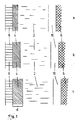
- Figure 1 shows the simple structure of the camouflage film in three different settings.
- An infrared-transparent, dielectric interference layer 4 is located on a preferably infrared-transparent carrier film 2 (for example made of polyethylene).
- the film covers the object 6 to be camouflaged against an observer.
- a protective layer 8 can optionally be used; in any case, it must be transparent in the IR frequency range of the application.
- the area 10 represents the air space between the film and the object.
- the layer thickness d of the interference layer determines the amount of heat radiation, the emissivity, the overall arrangement of film and object.
- ⁇ is related to the center of the atmospheric window (approximately 4 ⁇ m and 10 ⁇ m). This is a low IR permeability and a low heat radiation from the object to be camouflaged and camouflage film aims.
- the opposite extreme case high emission, high surface temperature is set by the arrangement according to FIG. 1c and a medium state according to FIG. 1b.
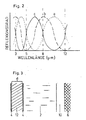
- FIG. 2 shows the spectral course of the reflectance of the three arrangements outlined in FIG. 1. It can be seen how the reflection maxima are shifted in relation to the atmospheric windows and how the described effect arises.
- the selection is based on the required transmission range in the infrared and optical spectrum, as well as on practical and technical aspects such as manufacturability, durability and costs.
- the group of semiconductors such as silicon, germanium, graphite, as well as metal sulfides, metal selenides and metal tellurides, which are also used as raw materials for compact IR windows, offers broadband camouflage and good stability. If transparency in the optical field is additionally desired, oxidic materials such as SiO2, Al2O3, SnO2, In2O3, TiO2, CeO2, MgO, fluorides such as MgF2, PbF2, BaF2 and other compounds with similar properties can be used.
- the refractive index of the layer and its dispersion i.e. its spectral course.
- High refractive indices are generally advantageous since the required layer thickness decreases with increasing n and the camouflage effect is still present even at increasingly oblique viewing angles.
- the dispersion must be taken into account if a simultaneous effect in both atmospheric windows is to be optimized.
- n3 average refractive index in the 3rd atmospheric window
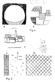
- FIG. 3 shows, instead of a compact inference layer, the use of a multilayer system in which two thinner films 4 with a high refractive index are separated by the layer 12 with a low refractive index at a distance d.
- a transparent plastic film can be used as the layer 12, which is, for example, identical to the carrier film 2.
- the layers 4 can be made much thinner than the above ⁇ / 4 layers, so that the arrangement is given greater flexibility, which has a very advantageous effect for many applications.
- the optical effect of this arrangement corresponds to the one-layer interference.
- the air gap 10 is located between the carrier film 2 and the object 6 to be camouflaged.
- the camouflage film according to the invention can be used very advantageously for cladding radomes (radomes).
- radomes cladding radomes
- the current construction of radomes has proven to be extremely unfavorable in terms of detectability in the IR range. Due to the low thermal conductivity and heat capacity of the radome outer skin (plastic foam material or foils), the surface temperature is subject to strong weather-related fluctuations, which gives these objects an unusually well-defined thermal image signature. Countermeasures with conventional camouflage means without impairing the radar transmission are not known.
- FIG. 4a shows a typical signature of a radome in the sun.
- the upper half of the sphere is warmed up and stands out against the much darker background.
- the light-dark conditions are just the other way around due to the low sky temperature, but just as easily recognizable.
- effective contour decomposition is brought about by typical structures of the surroundings, such as rectangular ones Areas in agricultural fields ( Figure 4b, without background) or settlements, building structures ( Figure 4c) or other landscape formations (horizon lines, ranges of hills, forest areas, river courses) can be simulated.
- camouflage film according to the invention does not have to be present at all times — like a coat of paint — since, if necessary, it can be spread out and removed again very quickly. For some objects, such as roads and airfield systems, this is the only conceivable solution.
- FIG. 5 shows a cross section through this arrangement.
- the IR-active camouflage film with plastic carrier 2 and interference layer 4 is connected directly to the radar absorber material 14.
- the above-mentioned variants for contour decomposition and signature simulation can of course also be used advantageously here.
- An additional camouflage effect in the visible or near infrared is possible by using colored plastic films. If foils with good optical transparency are used, then the visual camouflage effect can be achieved by means of deposited and thus easily changed paint coats, or it is already given by the existing camouflage of the object.
- camouflage film according to the invention In the conceivable application of the camouflage film according to the invention to vehicles, ships, airplanes, steel bridges, steel masts and the like, there is a special aspect. Due to their predominantly metal structure, these objects have a clear and characteristic radar signature. This problem can basically be solved by using radar absorbers and multispectral camouflage film, as described above. However, if radar absorbers are not desired or not possible for any reason (weight, cost, availability), then a combined IR-radar camouflage effect can be achieved with the camouflage film according to the invention by metallizing the film over the whole or part of the object. In this way, certain characteristic radar signatures of the object can be canceled or falsified.
Landscapes
- Engineering & Computer Science (AREA)
- General Engineering & Computer Science (AREA)
- Aiming, Guidance, Guns With A Light Source, Armor, Camouflage, And Targets (AREA)
- Details Of Aerials (AREA)
Applications Claiming Priority (2)
| Application Number | Priority Date | Filing Date | Title |
|---|---|---|---|
| DE19863614017 DE3614017A1 (de) | 1986-04-25 | 1986-04-25 | Multispektrale tarnfolie |
| DE3614017 | 1986-04-25 |
Publications (2)
| Publication Number | Publication Date |
|---|---|
| EP0250741A1 true EP0250741A1 (fr) | 1988-01-07 |
| EP0250741B1 EP0250741B1 (fr) | 1989-12-13 |
Family
ID=6299516
Family Applications (1)
| Application Number | Title | Priority Date | Filing Date |
|---|---|---|---|
| EP87105583A Expired EP0250741B1 (fr) | 1986-04-25 | 1987-04-15 | Feuille de camouflage multispectrale |
Country Status (2)
| Country | Link |
|---|---|
| EP (1) | EP0250741B1 (fr) |
| DE (2) | DE3614017A1 (fr) |
Cited By (2)
| Publication number | Priority date | Publication date | Assignee | Title |
|---|---|---|---|---|
| FR2857458A1 (fr) * | 2003-07-09 | 2005-01-14 | Centre Nat Rech Scient | Antenne thermique. |
| CN111435065A (zh) * | 2019-08-15 | 2020-07-21 | 宁波曙翔新材料股份有限公司 | 一种用于变换伪装器材伪装模式的装置及其应用 |
Families Citing this family (6)
| Publication number | Priority date | Publication date | Assignee | Title |
|---|---|---|---|---|
| DE4012782A1 (de) * | 1990-04-21 | 1991-10-24 | Telefunken Systemtechnik | Absorber |
| DE4330224C2 (de) * | 1993-09-07 | 1996-04-18 | Daimler Benz Aerospace Ag | Radom für Radaranlagen |
| DE4341806C1 (de) * | 1993-12-08 | 1995-06-08 | Daimler Benz Aerospace Ag | Verfahren zur Herstellung eines selbsttragenden Radoms |
| DE9408490U1 (de) * | 1994-05-25 | 1995-09-28 | Ernst Fehr technische Vertretungen und Beratung, Goldach | Strahlenschirmschutzauflage |
| EP0737840A3 (fr) * | 1995-04-07 | 1996-11-13 | Daimler-Benz Aerospace Aktiengesellschaft | Dispositif et méthode de camouflage |
| DE59800617D1 (de) | 1997-02-12 | 2001-05-17 | Schweizerische Eidgenossenschaft Eidgenoessisches Militaer Departement Gruppe Ruestung | Tarnstruktur |
Citations (2)
| Publication number | Priority date | Publication date | Assignee | Title |
|---|---|---|---|---|
| DE3043381C2 (de) * | 1980-11-18 | 1982-11-11 | Dornier System Gmbh, 7990 Friedrichshafen | Verwendung von spektralselektiv beschichteten Oberflächen sowie Verfahren zu ihrer Herstellung |
| DE3217977A1 (de) * | 1982-05-13 | 1983-11-17 | Bundesrepublik Deutschland, vertreten durch den Bundesminister der Verteidigung, dieser vertreten durch den Präsidenten des Bundesamtes für Wehrtechnik und Beschaffung, 5400 Koblenz | Vorrichtung zur tarnung von objekten gegen eine aufklaerung durch waermebildgeraete |
Family Cites Families (2)
| Publication number | Priority date | Publication date | Assignee | Title |
|---|---|---|---|---|
| NL273666A (fr) * | 1961-02-02 | |||
| US4529633A (en) * | 1983-01-14 | 1985-07-16 | Diab-Barracuda Ab | Thermal camouflage |
-
1986
- 1986-04-25 DE DE19863614017 patent/DE3614017A1/de not_active Withdrawn
-
1987
- 1987-04-15 EP EP87105583A patent/EP0250741B1/fr not_active Expired
- 1987-04-15 DE DE8787105583T patent/DE3761171D1/de not_active Expired - Fee Related
Patent Citations (2)
| Publication number | Priority date | Publication date | Assignee | Title |
|---|---|---|---|---|
| DE3043381C2 (de) * | 1980-11-18 | 1982-11-11 | Dornier System Gmbh, 7990 Friedrichshafen | Verwendung von spektralselektiv beschichteten Oberflächen sowie Verfahren zu ihrer Herstellung |
| DE3217977A1 (de) * | 1982-05-13 | 1983-11-17 | Bundesrepublik Deutschland, vertreten durch den Bundesminister der Verteidigung, dieser vertreten durch den Präsidenten des Bundesamtes für Wehrtechnik und Beschaffung, 5400 Koblenz | Vorrichtung zur tarnung von objekten gegen eine aufklaerung durch waermebildgeraete |
Cited By (3)
| Publication number | Priority date | Publication date | Assignee | Title |
|---|---|---|---|---|
| FR2857458A1 (fr) * | 2003-07-09 | 2005-01-14 | Centre Nat Rech Scient | Antenne thermique. |
| CN111435065A (zh) * | 2019-08-15 | 2020-07-21 | 宁波曙翔新材料股份有限公司 | 一种用于变换伪装器材伪装模式的装置及其应用 |
| CN111435065B (zh) * | 2019-08-15 | 2023-06-27 | 宁波曙翔新材料股份有限公司 | 一种用于变换伪装器材伪装模式的装置及其应用 |
Also Published As
| Publication number | Publication date |
|---|---|
| DE3614017A1 (de) | 1987-10-29 |
| EP0250741B1 (fr) | 1989-12-13 |
| DE3761171D1 (de) | 1990-01-18 |
Similar Documents
| Publication | Publication Date | Title |
|---|---|---|
| EP0250742B1 (fr) | Feuille transparente pour radar à réflexion infrarouge ajustable, à usage de camouflage | |
| DE69706243T2 (de) | Persönliche Schutzauskleidung für die Infanterie | |
| DE1916326A1 (de) | Tarnungsmittel zum Verhindern oder Hemmen der Entdeckung durch Radarerkundung | |
| DE4023287A1 (de) | Tarnnetz | |
| DE69814508T2 (de) | Antireflexionsschicht mit elektromagnetischem Abschirmeffekt und optisches Bauteil mit diesem Antireflexionsschicht | |
| EP0250741B1 (fr) | Feuille de camouflage multispectrale | |
| EP0021119A2 (fr) | Tente pour emploi civil et militaire | |
| DE3135586C2 (fr) | ||
| DE2700202C1 (de) | Breitbandige Tarnung | |
| DE4418214C2 (de) | Anstrichstoff mit niedrigem Emissionsvermögen im Bereich der Wärmestrahlung | |
| EP1389727A2 (fr) | Plaque de camouflage thermique | |
| DE69619153T2 (de) | Verbundwerkstoffstruktur, fähig zur Absorption und Dissipation von auffallender elektromagnetischer Strahlungsenergie, insbesondere für Luft-, See- und Landfahrzeuge und für feste Bodeneinrichtungen | |
| DE4400512C2 (de) | Starre Isolierhülle für einen Waffenlauf | |
| EP0912875B1 (fr) | Structure de camouflage | |
| EP1102028A2 (fr) | Dispositif de camouflage infrarouge | |
| EP0137930A2 (fr) | Revêtement protecteur ou fenêtre | |
| DE3148429A1 (de) | Ir-tarnvorrichtung fuer luftfahrzeuge | |
| WO2020208057A1 (fr) | Antenne radar | |
| DE19710692A1 (de) | Verfahren zur IR-Tarnung sowie IR-Reflektor | |
| EP1990600A2 (fr) | Système de sécurité contre les ondes de pression dangereuses dans des dispositifs militaires comme les camouflages de radar ou les blindages | |
| DE102019209508B4 (de) | Verfahren und Vorrichtung zur Erfassung eines Raumbereichs mittels Radarwellen | |
| DE102009019635B4 (de) | Optisches Bauelement sowie dessen Verwendung | |
| DE3410502C2 (de) | Regen-Erosionsschutz | |
| DE2103077A1 (de) | Wärmetarnung | |
| DE4216837A1 (de) | Radartarnung für langsamfliegende rollstabilisierte Flugkörper |
Legal Events
| Date | Code | Title | Description |
|---|---|---|---|
| PUAI | Public reference made under article 153(3) epc to a published international application that has entered the european phase |
Free format text: ORIGINAL CODE: 0009012 |
|
| AK | Designated contracting states |
Kind code of ref document: A1 Designated state(s): CH DE FR GB IT LI SE |
|
| 17P | Request for examination filed |
Effective date: 19880202 |
|
| 17Q | First examination report despatched |
Effective date: 19880929 |
|
| RAP1 | Party data changed (applicant data changed or rights of an application transferred) |
Owner name: DORNIER GMBH |
|
| GRAA | (expected) grant |
Free format text: ORIGINAL CODE: 0009210 |
|
| AK | Designated contracting states |
Kind code of ref document: B1 Designated state(s): CH DE FR GB IT LI SE |
|
| PG25 | Lapsed in a contracting state [announced via postgrant information from national office to epo] |
Ref country code: SE Effective date: 19891213 |
|
| GBT | Gb: translation of ep patent filed (gb section 77(6)(a)/1977) | ||
| REF | Corresponds to: |
Ref document number: 3761171 Country of ref document: DE Date of ref document: 19900118 |
|
| ET | Fr: translation filed | ||
| ITF | It: translation for a ep patent filed | ||
| PG25 | Lapsed in a contracting state [announced via postgrant information from national office to epo] |
Ref country code: LI Effective date: 19900430 Ref country code: CH Effective date: 19900430 |
|
| PLBE | No opposition filed within time limit |
Free format text: ORIGINAL CODE: 0009261 |
|
| STAA | Information on the status of an ep patent application or granted ep patent |
Free format text: STATUS: NO OPPOSITION FILED WITHIN TIME LIMIT |
|
| 26N | No opposition filed | ||
| REG | Reference to a national code |
Ref country code: CH Ref legal event code: PL |
|
| ITTA | It: last paid annual fee | ||
| REG | Reference to a national code |
Ref country code: GB Ref legal event code: IF02 |
|
| PGFP | Annual fee paid to national office [announced via postgrant information from national office to epo] |
Ref country code: GB Payment date: 20030326 Year of fee payment: 17 |
|
| PGFP | Annual fee paid to national office [announced via postgrant information from national office to epo] |
Ref country code: DE Payment date: 20030331 Year of fee payment: 17 |
|
| PGFP | Annual fee paid to national office [announced via postgrant information from national office to epo] |
Ref country code: FR Payment date: 20030408 Year of fee payment: 17 |
|
| PG25 | Lapsed in a contracting state [announced via postgrant information from national office to epo] |
Ref country code: GB Free format text: LAPSE BECAUSE OF NON-PAYMENT OF DUE FEES Effective date: 20040415 |
|
| PG25 | Lapsed in a contracting state [announced via postgrant information from national office to epo] |
Ref country code: DE Free format text: LAPSE BECAUSE OF NON-PAYMENT OF DUE FEES Effective date: 20041103 |
|
| GBPC | Gb: european patent ceased through non-payment of renewal fee |
Effective date: 20040415 |
|
| PG25 | Lapsed in a contracting state [announced via postgrant information from national office to epo] |
Ref country code: FR Free format text: LAPSE BECAUSE OF NON-PAYMENT OF DUE FEES Effective date: 20041231 |
|
| REG | Reference to a national code |
Ref country code: FR Ref legal event code: ST |
|
| PG25 | Lapsed in a contracting state [announced via postgrant information from national office to epo] |
Ref country code: IT Free format text: LAPSE BECAUSE OF NON-PAYMENT OF DUE FEES;WARNING: LAPSES OF ITALIAN PATENTS WITH EFFECTIVE DATE BEFORE 2007 MAY HAVE OCCURRED AT ANY TIME BEFORE 2007. THE CORRECT EFFECTIVE DATE MAY BE DIFFERENT FROM THE ONE RECORDED. Effective date: 20050415 |