EP0250841A2 - Procédé pour mesurer à distance la température d'un corps ainsi qu'un dispositif à cet effet - Google Patents
Procédé pour mesurer à distance la température d'un corps ainsi qu'un dispositif à cet effet Download PDFInfo
- Publication number
- EP0250841A2 EP0250841A2 EP87107439A EP87107439A EP0250841A2 EP 0250841 A2 EP0250841 A2 EP 0250841A2 EP 87107439 A EP87107439 A EP 87107439A EP 87107439 A EP87107439 A EP 87107439A EP 0250841 A2 EP0250841 A2 EP 0250841A2
- Authority
- EP
- European Patent Office
- Prior art keywords
- sensor
- temperature
- chopper
- preferably according
- arrangement
- Prior art date
- Legal status (The legal status is an assumption and is not a legal conclusion. Google has not performed a legal analysis and makes no representation as to the accuracy of the status listed.)
- Granted
Links
Images
Classifications
-
- G—PHYSICS
- G01—MEASURING; TESTING
- G01J—MEASUREMENT OF INTENSITY, VELOCITY, SPECTRAL CONTENT, POLARISATION, PHASE OR PULSE CHARACTERISTICS OF INFRARED, VISIBLE OR ULTRAVIOLET LIGHT; COLORIMETRY; RADIATION PYROMETRY
- G01J5/00—Radiation pyrometry, e.g. infrared or optical thermometry
- G01J5/02—Constructional details
- G01J5/08—Optical arrangements
- G01J5/0803—Arrangements for time-dependent attenuation of radiation signals
- G01J5/0805—Means for chopping radiation
-
- G—PHYSICS
- G01—MEASURING; TESTING
- G01J—MEASUREMENT OF INTENSITY, VELOCITY, SPECTRAL CONTENT, POLARISATION, PHASE OR PULSE CHARACTERISTICS OF INFRARED, VISIBLE OR ULTRAVIOLET LIGHT; COLORIMETRY; RADIATION PYROMETRY
- G01J5/00—Radiation pyrometry, e.g. infrared or optical thermometry
- G01J5/02—Constructional details
- G01J5/06—Arrangements for eliminating effects of disturbing radiation; Arrangements for compensating changes in sensitivity
- G01J5/064—Ambient temperature sensor; Housing temperature sensor; Constructional details thereof
Definitions
- the present invention relates to a method for the contactless measurement of a temperature of a body and an arrangement for the contactless measurement of a temperature of a body.
- the invention proposes that chops the heat radiation between the body and a temperature sensor using a chopper, - At least one ambient temperature of the sensor on the side of the chopper facing the sensor is taken into account when evaluating the temperature detected by the sensor.
- the fact that the heat radiation is chopped between the body and the intended temperature sensor results in heat radiation pulses detected by the sensor, the amplitude of which is given by two heat radiation components, namely firstly by the ambient radiation on the sensor side of the chopper and secondly the heat radiation on the side of the chopper facing away from the sensor, which is composed of the ambient radiation there and the body radiation to be detected.
- the ambient radiation on the side of the chopper facing away from the sensor cannot be separated from the body radiation, on the other hand e.g. can be reduced to an insignificant amount by minimizing the distance between the chopper and the body, and is furthermore practically time-invariant
- the ambient radiation on the sensor side of the chopper is a more acute problem, especially when one considers its change in time as it occurs after the sensor and chopper have been started occurs, due to electrical supplies and generally the chopper work and the fact that mounting elements for the sensor and chopper define relatively small-volume spaces, which result in temperature changes despite a stable, large-scale temperature.
- the heat radiation from the sensor housing has a direct effect on the actual sensor, usually a semiconductor chip integrated in the housing.
- Another, preferably not negligible radiation source is the chopper. Because of the work performed by him, especially if it is a mechanically moving chopper, he acts in the ambient air like a Joule brake, which further suggests that an ambient temperature is taken into account a temperature caused by the chopper's work.
- the temperature of the sensor housing be regulated to a predetermined value, if necessary also the temperature caused by the chopper.
- the heat radiation is chopped up using a mechanically moving chopper, such as a disk, with radiation-impermeable and radiation-transmissive segments, it is proposed that a temperature in the region of the chopper movement path be taken into account as an ambient temperature.
- the temperature measured by means of the sensor be corrected as a function of the temperature brought about by the chopper.
- the procedure is preferably further such that a first signal, which is dependent on the temperature caused by chopping work, is multiplied by a first coefficient, then added to a second, to obtain a second signal, and then a third signal, which is dependent on the temperature detected by the sensor divides the second, to obtain a fourth signal, and adds the fourth signal to the first signal, to obtain one for a body temperature, respectively.
- Radiation representative signal a first signal, which is dependent on the temperature caused by chopping work, is multiplied by a first coefficient, then added to a second, to obtain a second signal, and then a third signal, which is dependent on the temperature detected by the sensor divides the second, to obtain a fourth signal, and adds the fourth signal to the first signal, to obtain one for a body temperature, respectively.
- the sensor output signal is preferably averaged over a number of chopper periods before further evaluation in order to randomly eliminate fluctuations in the sensor output signal.
- coefficients for the correction of the sensor output signal on the basis of the temperature caused by chopper work are preferably determined and stored experimentally from at least two measurements, at predetermined body temperatures and two values of the temperature caused by work of the chopper.
- a temperature measurement on a thermally unbalanced body is representative of the thermal energy content of a body volume element lying directly in the area of the measurement.
- Such an indentation can be, for example, the opening of a can to be measured as a body, or an indentation, such as in the form of a bore, is provided in the case of bodies which do not yet have such an indentation, such as metal bars, whereby the temperature measurement mentioned for the thermal energy content of a much larger body volume element becomes representative, but the indentation provided acts like a body radiating like a black body and emits heat radiation that corresponds to the heat content averaged over a relatively large adjacent volume.
- the chopper period be selected to be shorter than the period during which the indentation is in the sensor measuring range, so that a sufficient number of measuring points are available during this measuring time to be able to carry out a random-size-eliminating averaging.
- the arrangement according to the invention for the contactless measurement of a temperature of a body comprises according to the invention - a first temperature sensor - A heat radiation chopper connected upstream of the heat input of the sensor - At least one further temperature sensor in the area of the chopper and / or the first temperature sensor, both on the sensor side of the chopper.
- the or a further temperature sensor is preferably thermally closely coupled to a housing of the first temperature sensor and / or to the chopper.
- At least one further temperature sensor is connected as a controlled variable receiver in a temperature control circuit for the area in which it is arranged.
- the chopper is a mechanically moved chopper, such as a chopper disc, with a large number of segments that are impermeable and permeable to heat radiation, and that the or a further temperature sensor is arranged directly in the region of the chopper movement path.
- the above-mentioned arrangement of the further temperature sensor in the region of the chopper movement path is extremely favorable, which is to say by taking the time-variable temperature detected by this sensor for the measurement result is made possible to measure representative immediately after switching on the arrangement.
- the time-variable behavior of the radiation can be eliminated by providing one or more control loops, the effort for this is relatively large, especially if one takes into account that heating and / or cooling organs, such as Peltier elements, must be provided as temperature actuators and such control loops, as was also mentioned, are sluggish.
- control loops can in principle be avoided by providing an evaluation unit to which the outputs of at least some of the temperature sensors are fed and which outputs a signal representative of the body temperature on the output side.
- an indentation is provided on a body to be measured and such bodies are moved relative to the temperature sensor, it is essential to provide a criterion that indicates when a temperature measurement with regard to the moving body in the right place, ie in the area of the indentation and when it does not.
- This is preferably solved in such a way that the first sensor is followed by a threshold-sensitive unit, the output of which effectively connects the output of the first sensor mentioned to an output of the arrangement when the value of the sensor output signal is above or below a predetermined level.
- the aforementioned threshold-sensitive unit makes it possible to detect , from when the mentioned indentation lies in the measuring range of the sensor.
- the sensor and the threshold-sensitive unit are preferably designed such that they respond to a predetermined change in the temperature or radiation detected by means of the first sensor per unit of time, with which radiation changes or flanks trigger the measurement, regardless of the prevailing temperature levels.
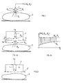
- the 1 shows a temperature sensor 1, for example in the form of a pyroelectric detector, which is arranged in the region of a body 3 without contact.
- the sensor 1 usually acts as a thermal electrical converter and gives, on the output side, a signal S in the arrangement shown in function of a body temperature or radiation -3 and the ambient radiation corresponding to a temperature ⁇ u . If the radiation of the body 3 is not significantly different from the ambient radiation in that its temperature, for example below 100 ° C., is at an ambient temperature of 20 ° C., the ambient radiation influences the measurement accuracy to an unacceptable degree. This is particularly the case if, for reasons to be described below, the ambient radiation is not constant, but is time-variant.
- a heat radiation chopper 5 is now arranged between the body 3 to be measured with the radiation corresponding to ⁇ 3 and the sensor 1, for example a mechanical chopper, by means of which segments 5a which are impermeable to heat radiation alternate with segments 5b which are permeable to heat radiation, as indicated by the arrow p, between the sensor 1 and the body 3 are moved through.
- the reverse Exercise radiation with respect to the chopper 5, sensor-1-sided is denoted by ⁇ u1
- the ambient radiation with respect to the chopper 5 body-3-sided is denoted by ⁇ u2 .
- the signal shown in FIG. 2b appears qualitatively at the output of sensor 1.
- the radiation level detected by the sensor 1 corresponds to the lower envelope ⁇ u1 shown in FIG. 2b corresponding to the radiation ⁇ u1 . If the radiation between body 3 and sensor 1 is released by a segment 5b, the detected radiation corresponds to a value that results from the ambient radiation corresponding to ⁇ u2 and the body radiation ⁇ 3. While the ambient radiation ⁇ u2 on the body side can be reduced by positioning the chopper 5 as close as possible to the body 3, the ambient radiation ⁇ u1 on the sensor side is much more problematic to control. Usually, an arrangement, as shown schematically in FIG.
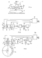
- sensor 1 which is usually electrically fed via feed lines 9 and usually has an integrated amplifier, thus its housing 11, and secondly the chopper 5, in particular if, as shown by the arrow p, it is a mechanical chopper .
- a first correction temperature sensor 13 is thermally closely coupled to the sensor housing 11 and a further correction temperature sensor 15 to the chopper 5 in the case of a mechanical chopper in such a way that the sensor 15 is directly in the Area of the path of movement of the chopper 15 is arranged such that it measures the temperature of the ambient air of the chopper.
- FIG. 5 schematically shows a first variant of how the signals from sensors 1, 13 and 15 are evaluated.
- the measuring sensor 1 is embedded in a relatively large-volume, thermally highly conductive, for example metal body 17, to which on the one hand the sensor 13 is thermally closely coupled and on the other hand a temperature control element 19 such as a Peltier element.
- the dependent on the housing temperature of the housing 11 output signal S11 of the sensor 13 is processed and amplified at most on a unit 21, then supplied as a control variable X to a differential unit 23.
- the latter is at a manipulated variable input W an adjustable setpoint or command value W, adjustable on an adjustable signal source 25.
- a control difference signal ⁇ is fed via a controller 27 to the temperature control element 19, such as a Peltier element, so that the temperature of the block 17 is at a value corresponding to the the unit 25 set target value W is set.
- the housing temperature of the housing 11 is thus kept constant and is known. Because of the relatively low inertia of the housing 11 and block 17 to changes in temperature, the thermal stability of the housing 11 can be achieved quickly, so that after activating the arrangement shown, a relevant one can quickly be found with regard to errors caused by thermal instabilities of the housing 11 Measurement can be made.
- the output S5 of the sensor 15, which detects the temperature change caused by the work of the chopper 5 is connected together with the output S of the measurement sensor 1 to an evaluation unit 29, at the output of which a signal S ( ⁇ 3) appears, which is representative of the radiation from the body 3 and is determined from the calculation of the measurement sensor output signal S and the output signal S5 of the sensor 15.
- the evaluation unit reference is made to FIG. 7, which is described further below.
- FIG. 6 A further embodiment variant is shown in FIG. 6, in which the temperature is now regulated in the region of the chopper movement path.
- a chopper is usually and to obtain high chopper frequencies not only in the embodiment variant according to this figure, but, if a mechanical chopper is used, also in the other embodiment variants, a chopper disc 5 ⁇ driven by a motor 31, which segments 5a and radiation-transmissive segments 5b are impermeable to radiation has used.
- the output of the sensor 15, which measures the temperature directly in the region of the chopper 5 ⁇ movement path, at most after amplification and processing on a unit 21a as a controlled variable signal X is led to a differential unit 23a, the second input of which is analogous to 5, a command or setpoint value signal W is supplied, which can be set on an adjustable signal source 25a.
- the control difference signal ⁇ appearing on the output side of the differential unit 23a is fed via a controller 27a to a temperature control element 19a, such as, for example, a Peltier element 33 which is thermally closely coupled to the chopper disk 5 ⁇ .
- This control circuit is normally slower than that shown in Fig. 5, due to the thermal transmission inertia between axis 33 and the periphery of the disc 5 ⁇ , where due to the high peripheral speed, the highest ambient temperatures, so that also for control stability reasons There are limits to the speed of this control loop.
- this arrangement can be selected, at most in addition to a regulation according to FIG. 5, in particular when an opto-electric chopper, such as a Kerr cell, is used.
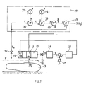
- FIG. 7 shows the evaluation unit 29 on the basis of function blocks and based on the embodiment variant according to FIG. 5.
- ⁇ 3 the prevailing temperature due to the heat radiation of the body 3 at the location of the sensor 1
- ⁇ 1 the temperature measured with sensor 1
- S ⁇ 5 the temperature measured in the immediate area of the path of movement of the chopper 5 by means of the sensor 15, corresponding to S5 a
- b experimentally determined coefficients resp. Constants that depend on the nature of the body 3 and the arrangement of the chopper 5, sensor 1 and other measures provided in the sensor / chopper area.
- the output signal of the sensor 15 on the evaluation unit 29 is first fed to a multiplication unit 35, the second input of which is supplied with the adjustable coefficient b, as a gain factor.
- the coefficient b is set on a setting unit 37 and stored there.
- the output of the multiplication unit 35 is fed to an addition unit 39, the second input of which is the variable a, which can be set on an adjusting unit 41.
- the output of the addition unit 39 is fed to the denominator input of a division unit 43, to the counter input of which the output signal of the sensor 1 is fed.
- the output signal of the division unit 43 is added to the output signal of the sensor 15 at a summation unit 45; on the output side of the addition unit 45, a signal S ( ⁇ 3) representative of the temperature ⁇ 3 corresponding to the body radiation appears.
- the coefficients a and b in the equation given above, which are set on the evaluation unit 29, are determined experimentally, for example, in such a way that with at least two predetermined, constant body temperatures of the body 3, each with two different temperatures in the chopper area detected by the sensor 15, by means of the adjustable units 37 and 41, the output signal of the evaluation unit 29 is set such that the signal then appearing indicates the respective body temperature independently of the temperatures detected by the sensor 15.
- Two different temperatures detected by the sensor 15 are generated, for example, by taking a first measurement immediately after the chopper 5 is started up and a respective second measurement after thermal stabilization of the temperature detected by the said sensor 15.
- a relatively accurate temperature measurement of the heat radiation from a body surface is only representative of the thermal energy content of a relatively small volume element around that body point that is currently in the area of the measurement sensor 1, if the body is not isothermal.
- the bore radiates thermally like a black body and is therefore representative of the thermal energy content of a much larger volume element of the body than if only its surface radiation is detected.
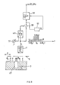
- FIG. 8 shows a signal processing / evaluation directly downstream of the sensor 1, which makes it possible to detect when a body which is moved in this way with respect to the sensor 1 appears in the area of the sensor 1 in a measurement-relevant manner.
- the body 3 as indicated by the arrow ⁇ 3, for determining its thermal energy content by means of a temperature measurement of the type described, provided with the recess 47, emits heat radiation corresponding to ist o on its surface, which is necessary for the thermal energy content of the surface zone, as represented by qualitative dash-dotted lines is representative.
- the body 3 emits the radiation in the region of the recess 47 speaking ⁇ E , which is representative of the thermal energy content of a larger body volume element, as shown qualitatively hatched.
- the body radiation is chopped up and strikes the sensor 1.
- a pyroelectric detector is usually used as sensor 1, which does not react to radiation values that are stationary over time, but rather to radiation changes per unit of time. For this reason too, the provision of the chopper is essential for the measurement of body radiation that does not change over time.
- the qualitatively represented pulses appear, with the chopper frequency f, which, as soon as the recess 47 arrives in the area of the sensor 1, are higher or lower than if only the surface and thus the radiation is correspondingly ⁇ o in the sensor area .
- a threshold-value-sensitive unit 49 connected downstream of the sensor 1, such as a comparator, with a threshold value R which can be set on an adjusting unit 51, it is determined from when the output pulses of the sensor 1 deviate from a value corresponding to the surface radiation ⁇ o . Then a switching element 53 is closed by the threshold-sensitive unit 49 and the pulses S ( ⁇ E ) which then occur are applied to an averaging unit 55 which, for example, comprises an integration element in which the values of the pulses now received are added up and the result divided by the number N of received pulses, the latter, for example by means of a Counter 57 is detected.
- the result of the mean value formed on the unit 55 is fed to the correspondingly provided evaluation unit 29 or 29a according to FIG. 7, 6 or 5.
- the chopper period inverse to the chopper frequency f5 is chosen so that it is significantly shorter than the time period during which, at a given speed v3 of the body, the recess 47 is present in the area of the sensor 1. Random fluctuations of the pulses corresponding to S ( ⁇ E ) are averaged out by averaging the unit 55.
- the threshold-sensitive unit 49 allows the arrangement to be switched to measurement-active precisely when the body 3 is in the measurement-relevant position via the switch 53.
- the temperature corresponding to the thermal radiation of a body can be measured without contact and this precise temperature measurement can be used to measure the thermal energy content of a large body volume element by providing a recess in the body, whereby the method and the arrangement makes it possible, for example on non-isothermal hollow bodies, such as cans on a production line, to obtain a representative value for their thermal energy content with a single temperature measurement, which is important, for example, when testing the density of such can bodies, where leakage-relevant pressure drops have to be separated from pressure change-related pressure drops , maW temperature compensation of the pressure relevant there must be carried out.
Landscapes
- Physics & Mathematics (AREA)
- General Physics & Mathematics (AREA)
- Spectroscopy & Molecular Physics (AREA)
- Radiation Pyrometers (AREA)
- Measuring Temperature Or Quantity Of Heat (AREA)
- Investigating Or Analyzing Materials Using Thermal Means (AREA)
Applications Claiming Priority (2)
| Application Number | Priority Date | Filing Date | Title |
|---|---|---|---|
| CH2503/86 | 1986-06-20 | ||
| CH250386 | 1986-06-20 |
Publications (3)
| Publication Number | Publication Date |
|---|---|
| EP0250841A2 true EP0250841A2 (fr) | 1988-01-07 |
| EP0250841A3 EP0250841A3 (en) | 1990-03-28 |
| EP0250841B1 EP0250841B1 (fr) | 1994-07-27 |
Family
ID=4235270
Family Applications (1)
| Application Number | Title | Priority Date | Filing Date |
|---|---|---|---|
| EP87107439A Expired - Lifetime EP0250841B1 (fr) | 1986-06-20 | 1987-05-22 | Procédé pour mesurer à distance la température d'un corps ainsi qu'un dispositif à cet effet |
Country Status (5)
| Country | Link |
|---|---|
| US (2) | US4887229A (fr) |
| EP (1) | EP0250841B1 (fr) |
| JP (1) | JPS6366426A (fr) |
| AT (1) | ATE109274T1 (fr) |
| DE (1) | DE3750278D1 (fr) |
Cited By (1)
| Publication number | Priority date | Publication date | Assignee | Title |
|---|---|---|---|---|
| EP0798545A1 (fr) * | 1996-03-26 | 1997-10-01 | Terumo Kabushiki Kaisha | Thermométre sans contact |
Families Citing this family (13)
| Publication number | Priority date | Publication date | Assignee | Title |
|---|---|---|---|---|
| EP0250841B1 (fr) * | 1986-06-20 | 1994-07-27 | Lehmann, Martin | Procédé pour mesurer à distance la température d'un corps ainsi qu'un dispositif à cet effet |
| US4982347A (en) * | 1989-06-22 | 1991-01-01 | Unisys Corporation | Process and apparatus for producing temperature profiles in a workpiece as it passes through a belt furnace |
| JPH04372828A (ja) * | 1991-06-24 | 1992-12-25 | Matsushita Electric Ind Co Ltd | 熱画像検出装置 |
| US5251263A (en) * | 1992-05-22 | 1993-10-05 | Andrea Electronics Corporation | Adaptive noise cancellation and speech enhancement system and apparatus therefor |
| US5246292A (en) * | 1992-05-28 | 1993-09-21 | Eli Gal | Temperature measurement apparatus |
| US5577840A (en) * | 1993-05-15 | 1996-11-26 | Horiba, Ltd. | Method of measuring temperature by use of an infrared sensor |
| DE4331574C2 (de) * | 1993-09-16 | 1997-07-10 | Heimann Optoelectronics Gmbh | Infrarot-Sensormodul |
| US5884235A (en) * | 1996-12-17 | 1999-03-16 | Integrated Systems, Inc. | Non-contact, zero-flux temperature sensor |
| IL119956A (en) | 1997-01-01 | 2003-11-23 | Opgal Optronic Ind Ltd | Brake monitoring system and method |
| US6831465B2 (en) * | 2001-07-23 | 2004-12-14 | I F M Electronic Gmbh | Electrical measurement means |
| US6726357B2 (en) * | 2002-05-20 | 2004-04-27 | Hewlett-Packard Development Company, L.P. | Media identification system |
| US7150559B1 (en) * | 2002-09-25 | 2006-12-19 | Illinois Tool Works Inc. | Hot melt adhesive detection methods and systems |
| US8787606B2 (en) | 2009-04-15 | 2014-07-22 | Garth William Gobeli | Electronically compensated micro-speakers |
Family Cites Families (19)
| Publication number | Priority date | Publication date | Assignee | Title |
|---|---|---|---|---|
| FR1234318A (fr) * | 1959-05-15 | 1960-10-17 | Drivomatic | Pyromètre de mesure à distance |
| US3057200A (en) * | 1961-05-12 | 1962-10-09 | Hughes Aircraft Co | Pyrometer |
| US3293915A (en) * | 1963-08-05 | 1966-12-27 | Barnes Eng Co | Radiometer control means |
| GB1226540A (fr) * | 1967-12-12 | 1971-03-31 | ||
| US3794838A (en) * | 1972-02-10 | 1974-02-26 | Barnes Eng Co | Compensation means for ambient temperature changes of a radiation chopper in a radiometer |
| JPS5172382A (en) * | 1974-12-18 | 1976-06-23 | Hitachi Shipbuilding Eng Co | Hoshaondono keisokuhoho |
| IT1058697B (it) * | 1975-04-03 | 1982-05-10 | Rolls Royce 1971 Ltd | Pirometri |
| DE2519727B2 (de) * | 1975-05-02 | 1980-02-21 | Maatschappij Van Berkel's, Patent N.V., Rotterdam (Niederlande) | Verfahren zum Betrieb einer Wägevorrichtung |
| JPS5816143B2 (ja) * | 1975-06-26 | 1983-03-29 | 新日本製鐵株式会社 | キンゾクザイリヨウノヒヨウメンキズケンシユホウホウ |
| US4048500A (en) * | 1976-11-08 | 1977-09-13 | The United States Of America As Represented By The Secretary Of The Navy | Infrared background suppression |
| JPS56501138A (fr) * | 1979-09-12 | 1981-08-13 | ||
| JPS5640724A (en) * | 1979-09-12 | 1981-04-17 | Toshiba Corp | Infrared ray type temperature measuring device |
| US4435093A (en) * | 1981-12-08 | 1984-03-06 | Bethlehem Steel Corporation | Pyrometer with sighting window cleanliness monitor |
| US4527896A (en) * | 1982-03-04 | 1985-07-09 | Mikron Instrument Company, Inc. | Infrared transducer-transmitter for non-contact temperature measurement |
| JPS58216921A (ja) * | 1982-06-11 | 1983-12-16 | Toshiba Corp | 調理器の温度検知装置 |
| EP0219531B1 (fr) * | 1985-04-17 | 1999-07-14 | Thermoscan Inc. | Thermometre electronique a infrarouge et procede de mesure de la temperature |
| JPS62112021A (ja) * | 1985-11-11 | 1987-05-23 | Minolta Camera Co Ltd | 焦電型温度センサ |
| EP0250841B1 (fr) * | 1986-06-20 | 1994-07-27 | Lehmann, Martin | Procédé pour mesurer à distance la température d'un corps ainsi qu'un dispositif à cet effet |
| JPH0312631Y2 (fr) * | 1986-06-30 | 1991-03-25 |
-
1987
- 1987-05-22 EP EP87107439A patent/EP0250841B1/fr not_active Expired - Lifetime
- 1987-05-22 AT AT87107439T patent/ATE109274T1/de active
- 1987-05-22 DE DE3750278T patent/DE3750278D1/de not_active Expired - Fee Related
- 1987-06-19 JP JP62153190A patent/JPS6366426A/ja active Pending
- 1987-06-22 US US07/064,464 patent/US4887229A/en not_active Expired - Fee Related
-
1989
- 1989-08-22 US US07/396,913 patent/US4955727A/en not_active Expired - Fee Related
Cited By (2)
| Publication number | Priority date | Publication date | Assignee | Title |
|---|---|---|---|---|
| EP0798545A1 (fr) * | 1996-03-26 | 1997-10-01 | Terumo Kabushiki Kaisha | Thermométre sans contact |
| US6048092A (en) * | 1996-03-26 | 2000-04-11 | Terumo Kabushiki Kaisha | Noncontacting thermometer |
Also Published As
| Publication number | Publication date |
|---|---|
| DE3750278D1 (de) | 1994-09-01 |
| EP0250841B1 (fr) | 1994-07-27 |
| US4955727A (en) | 1990-09-11 |
| JPS6366426A (ja) | 1988-03-25 |
| EP0250841A3 (en) | 1990-03-28 |
| US4887229A (en) | 1989-12-12 |
| ATE109274T1 (de) | 1994-08-15 |
Similar Documents
| Publication | Publication Date | Title |
|---|---|---|
| EP0250841B1 (fr) | Procédé pour mesurer à distance la température d'un corps ainsi qu'un dispositif à cet effet | |
| DE69631931T2 (de) | Temperaturmesssystem und Sensoreinheit dafür | |
| DE60220364T2 (de) | Modul zum Steuern einer Drehabtriebswelle und Modul zum Ändern des Fahrzustandes eines Fahrzeugs | |
| EP1754395B1 (fr) | Procede de stabilisation de la dependance a la temperature de l'emission lumineuse d'une del | |
| DE2502917B2 (de) | Elektromagnetische Kompensations-Wägevorrichtung | |
| DE60035984T2 (de) | Verfahren zur Verringerung des Einflusses schwankender Umgebungsbedingungen auf ein Messgerät und dieses Verfahren verwendendes Messgerät | |
| DE3321783A1 (de) | Anordnung zum auswerten eines teststreifens | |
| EP0864852B1 (fr) | Balance électronique | |
| DE102008064011B3 (de) | Vorrichtung zur Erfassung der Innenraumtemperatur eines Fahrzeuges | |
| DE10013172C2 (de) | Verfahren und Vorrichtung zur photothermischen Analyse einer Materialschicht, insbesondere zur Schichtdickenmessung | |
| DE2818241A1 (de) | Heissbuchsen-detektor | |
| WO2002016958A2 (fr) | Systeme de detection et procede associe, en particulier pour la determination de distances | |
| CH675478A5 (fr) | ||
| DE3722000C2 (de) | Vorrichtung zur Messung der Temperatur eines Mediums, insbesondere zur Messung der Innenraumtemperatur in einem Kraftfahrzeug | |
| WO2005069693A1 (fr) | Procede pour commander un processus de cuisson sur une table de cuisson et table de cuisson permettant de mettre en oeuvre ce procede | |
| DE102005041050B4 (de) | Verfahren und Vorrichtung zur Korrektur des Ausgangssignals eines Strahlungssensors und zur Messung von Strahlung | |
| DE60310533T2 (de) | Verbesserungen in bezug auf die kalibration von infrarotkameras | |
| DE60025662T2 (de) | Strahlungsthermometer | |
| EP1155296B1 (fr) | Module capteur avec dispositif de traitement de signal integre | |
| DE10108852C1 (de) | Raumtemperaturregelung | |
| DE2731381B2 (de) | Schaltungsanordnung zur Überwachung einer Meßgröße | |
| DE69309960T2 (de) | Feuchtigkeitsmessvorrichtung | |
| EP4303577B1 (fr) | Ensemble capteur comprenant un capteur électrochimique et un capteur de température et procédé utilisant un tel ensemble capteur | |
| DE2200492B2 (de) | Kernstrahlungs-dickenmessvorrichtung | |
| DE4411853C2 (de) | Optoakustischer Gassensor zur gleichzeitigen Detektion von mehreren Komponenten eines Gasgemisches |
Legal Events
| Date | Code | Title | Description |
|---|---|---|---|
| PUAI | Public reference made under article 153(3) epc to a published international application that has entered the european phase |
Free format text: ORIGINAL CODE: 0009012 |
|
| AK | Designated contracting states |
Kind code of ref document: A2 Designated state(s): AT BE CH DE ES FR GB GR IT LI LU NL SE |
|
| 17P | Request for examination filed |
Effective date: 19880618 |
|
| PUAL | Search report despatched |
Free format text: ORIGINAL CODE: 0009013 |
|
| AK | Designated contracting states |
Kind code of ref document: A3 Designated state(s): AT BE CH DE ES FR GB GR IT LI LU NL SE |
|
| 17Q | First examination report despatched |
Effective date: 19920612 |
|
| GRAA | (expected) grant |
Free format text: ORIGINAL CODE: 0009210 |
|
| AK | Designated contracting states |
Kind code of ref document: B1 Designated state(s): AT BE CH DE ES FR GB GR IT LI LU NL SE |
|
| PG25 | Lapsed in a contracting state [announced via postgrant information from national office to epo] |
Ref country code: IT Free format text: LAPSE BECAUSE OF FAILURE TO SUBMIT A TRANSLATION OF THE DESCRIPTION OR TO PAY THE FEE WITHIN THE PRESCRIBED TIME-LIMIT;WARNING: LAPSES OF ITALIAN PATENTS WITH EFFECTIVE DATE BEFORE 2007 MAY HAVE OCCURRED AT ANY TIME BEFORE 2007. THE CORRECT EFFECTIVE DATE MAY BE DIFFERENT FROM THE ONE RECORDED. Effective date: 19940727 Ref country code: NL Effective date: 19940727 Ref country code: GR Free format text: LAPSE BECAUSE OF FAILURE TO SUBMIT A TRANSLATION OF THE DESCRIPTION OR TO PAY THE FEE WITHIN THE PRESCRIBED TIME-LIMIT Effective date: 19940727 Ref country code: GB Effective date: 19940727 |
|
| REF | Corresponds to: |
Ref document number: 109274 Country of ref document: AT Date of ref document: 19940815 Kind code of ref document: T |
|
| REF | Corresponds to: |
Ref document number: 3750278 Country of ref document: DE Date of ref document: 19940901 |
|
| ET | Fr: translation filed | ||
| PG25 | Lapsed in a contracting state [announced via postgrant information from national office to epo] |
Ref country code: SE Effective date: 19941027 |
|
| PG25 | Lapsed in a contracting state [announced via postgrant information from national office to epo] |
Ref country code: ES Free format text: LAPSE BECAUSE OF FAILURE TO SUBMIT A TRANSLATION OF THE DESCRIPTION OR TO PAY THE FEE WITHIN THE PRESCRIBED TIME-LIMIT Effective date: 19941107 |
|
| NLV1 | Nl: lapsed or annulled due to failure to fulfill the requirements of art. 29p and 29m of the patents act | ||
| GBV | Gb: ep patent (uk) treated as always having been void in accordance with gb section 77(7)/1977 [no translation filed] |
Effective date: 19940727 |
|
| PG25 | Lapsed in a contracting state [announced via postgrant information from national office to epo] |
Ref country code: AT Effective date: 19950522 |
|
| PG25 | Lapsed in a contracting state [announced via postgrant information from national office to epo] |
Ref country code: BE Effective date: 19950531 Ref country code: CH Effective date: 19950531 Ref country code: LI Effective date: 19950531 Ref country code: LU Free format text: LAPSE BECAUSE OF NON-PAYMENT OF DUE FEES Effective date: 19950531 |
|
| PLBE | No opposition filed within time limit |
Free format text: ORIGINAL CODE: 0009261 |
|
| STAA | Information on the status of an ep patent application or granted ep patent |
Free format text: STATUS: NO OPPOSITION FILED WITHIN TIME LIMIT |
|
| 26N | No opposition filed | ||
| BERE | Be: lapsed |
Owner name: LEHMANN MARTIN Effective date: 19950531 |
|
| REG | Reference to a national code |
Ref country code: CH Ref legal event code: PL |
|
| PG25 | Lapsed in a contracting state [announced via postgrant information from national office to epo] |
Ref country code: DE Effective date: 19960201 |
|
| PG25 | Lapsed in a contracting state [announced via postgrant information from national office to epo] |
Ref country code: FR Effective date: 19960229 |
|
| REG | Reference to a national code |
Ref country code: FR Ref legal event code: ST |
|
| REG | Reference to a national code |
Ref country code: FR Ref legal event code: ST |