EP0250907A2 - Dispositif de soulagement de traction pour lignes à ruban - Google Patents
Dispositif de soulagement de traction pour lignes à ruban Download PDFInfo
- Publication number
- EP0250907A2 EP0250907A2 EP87108028A EP87108028A EP0250907A2 EP 0250907 A2 EP0250907 A2 EP 0250907A2 EP 87108028 A EP87108028 A EP 87108028A EP 87108028 A EP87108028 A EP 87108028A EP 0250907 A2 EP0250907 A2 EP 0250907A2
- Authority
- EP
- European Patent Office
- Prior art keywords
- housing part
- pin
- insulating
- insulating material
- landline
- Prior art date
- Legal status (The legal status is an assumption and is not a legal conclusion. Google has not performed a legal analysis and makes no representation as to the accuracy of the status listed.)
- Withdrawn
Links
- 239000011810 insulating material Substances 0.000 claims abstract description 9
- 230000005405 multipole Effects 0.000 claims 1
- 238000011161 development Methods 0.000 description 6
- 230000018109 developmental process Effects 0.000 description 6
- 238000009413 insulation Methods 0.000 description 2
- 238000005452 bending Methods 0.000 description 1
- 238000003780 insertion Methods 0.000 description 1
- 230000037431 insertion Effects 0.000 description 1
- 238000004519 manufacturing process Methods 0.000 description 1
- 238000000034 method Methods 0.000 description 1
- 238000003825 pressing Methods 0.000 description 1
Images
Classifications
-
- H—ELECTRICITY
- H01—ELECTRIC ELEMENTS
- H01R—ELECTRICALLY-CONDUCTIVE CONNECTIONS; STRUCTURAL ASSOCIATIONS OF A PLURALITY OF MUTUALLY-INSULATED ELECTRICAL CONNECTING ELEMENTS; COUPLING DEVICES; CURRENT COLLECTORS
- H01R13/00—Details of coupling devices of the kinds covered by groups H01R12/70 or H01R24/00 - H01R33/00
- H01R13/58—Means for relieving strain on wire connection, e.g. cord grip, for avoiding loosening of connections between wires and terminals within a coupling device terminating a cable
- H01R13/5804—Means for relieving strain on wire connection, e.g. cord grip, for avoiding loosening of connections between wires and terminals within a coupling device terminating a cable comprising a separate cable clamping part
- H01R13/5812—Means for relieving strain on wire connection, e.g. cord grip, for avoiding loosening of connections between wires and terminals within a coupling device terminating a cable comprising a separate cable clamping part the cable clamping being achieved by mounting the separate part on the housing of the coupling device
-
- H—ELECTRICITY
- H02—GENERATION; CONVERSION OR DISTRIBUTION OF ELECTRIC POWER
- H02G—INSTALLATION OF ELECTRIC CABLES OR LINES, OR OF COMBINED OPTICAL AND ELECTRIC CABLES OR LINES
- H02G15/00—Cable fittings
- H02G15/007—Devices for relieving mechanical stress
Definitions
- the invention relates to a device for strain relief of multi-core electrical landlines on a housing part of an electrical component or device.
- the invention has for its object to provide a simple strain relief, in which the landline can be fixed without spending a lot of time and which enables a straight wire run.
- Such landlines serve, for example, as connecting lines between telephone systems and overhead line masts. These landlines have cores of increased strength and cross-section. Bending the cables or clamping them too tight increases the risk of breakage due to the higher brittleness.
- the spike-like insulating material is a simple part. The insertion into the connecting web is a simple straightforward process that can be carried out with a simple tool. The strain relief has no or only a minor effect on the wire core.
- the round cross section of the insulating pin according to claim 2 is easy to manufacture. Sharp cuts in the web are avoided, which reduces the risk of tearing open the insulation.
- the development according to claim 3 can be realized particularly inexpensively.
- fixing the cable it is first placed over the mandrel and pressed against its base. This pierces the insulation so that the cable is secured against longitudinal pull.
- the mandrel can have transverse ribs which make it difficult to pull out the line.
- a plurality of landlines can be attached in parallel to each other on the terminal block. Since the insulating pin can have a small width, it is possible, for example, two to attach single-core ridge cables individually and closely adjacent to the terminal block.
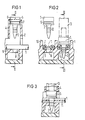
- a landline 1 is inserted into a housing part 2 of a terminal block for the landlines 1.
- a thorn-like tapered plastic pin 3 is held in a shaft above the landline 1.
- the tip of the insulating material pin 3 points to the web line 1.
- the insulating material pin 3 has a widespread foot end 5, into which a transverse groove 6 is embedded.
- a cam-like projection 7 of the shaft 4 engages in this, so that the insulating pin 3 is held in a defined position.
- the tip of the insulating pin 3 is directed towards a conical hole 8 in a bottom part 9 of the housing part 2.
- FIG. 2 shows another view of the parts according to FIG. 1.
- the two-wire landline 1 lies between two intermediate walls 10 of the housing part 2 centrally over the conical hole 8 of the bottom part 9.
- the hole 8 widens towards the insulating pin 3.
- Fig. 2 and in Fig. 3 are the Parts shown in their end position.
- the tip of the insulating material pin 3 is pierced through the connecting web 11 of the web line 1 and pressed into the conical hole 8 of the base part 9.
- the insulating pin 3 is provided with circumferential transverse ribs that taper towards the tip.
- the largest diameter of the transverse ribs 12 is somewhat larger than the narrowest diameter of the conical hole 8.
- the insulating pin 3 is pressed into the conical hole 8, the parts yield elastically to one another.
- the insulating pin 3 is pushed through the hole until the widespread foot end 5 rests on the landline 1.
- One of the transverse ribs then engages behind the bottom part 9, so that the insulating pin 3 is held firmly in the hole.
- a plurality of transverse ribs 12 arranged one above the other make it possible to fasten web lines of different thicknesses.
- Pressing the insulating pin 3 out of its latching position in the shaft 4 can e.g. by means of a stamp 13 indicated by dash-dotted lines.
- the shaft 4 pictures a guide for the extended foot part 5, so that the insulating pin 3 can easily hit the conical hole 8 in the bottom part 9.
Landscapes
- Installation Of Indoor Wiring (AREA)
- Insulating Bodies (AREA)
- Insulated Conductors (AREA)
- Insertion Pins And Rivets (AREA)
- Insertion, Bundling And Securing Of Wires For Electric Apparatuses (AREA)
Applications Claiming Priority (2)
| Application Number | Priority Date | Filing Date | Title |
|---|---|---|---|
| DE3621214 | 1986-06-25 | ||
| DE3621214 | 1986-06-25 |
Publications (2)
| Publication Number | Publication Date |
|---|---|
| EP0250907A2 true EP0250907A2 (fr) | 1988-01-07 |
| EP0250907A3 EP0250907A3 (fr) | 1988-09-14 |
Family
ID=6303625
Family Applications (1)
| Application Number | Title | Priority Date | Filing Date |
|---|---|---|---|
| EP87108028A Withdrawn EP0250907A3 (fr) | 1986-06-25 | 1987-06-03 | Dispositif de soulagement de traction pour lignes à ruban |
Country Status (3)
| Country | Link |
|---|---|
| EP (1) | EP0250907A3 (fr) |
| JP (1) | JPS6314495A (fr) |
| AU (1) | AU7464287A (fr) |
Cited By (2)
| Publication number | Priority date | Publication date | Assignee | Title |
|---|---|---|---|---|
| GB2342508A (en) * | 1998-07-08 | 2000-04-12 | R W Data Ltd | Gripping electrical cables |
| EP2999054A1 (fr) * | 2014-09-22 | 2016-03-23 | Tyco Electronics Simel S.A.S. | Vis de liaison pour un ensemble de connexion de fil et ensemble de connexion de fil |
Families Citing this family (1)
| Publication number | Priority date | Publication date | Assignee | Title |
|---|---|---|---|---|
| JPH11300608A (ja) * | 1998-04-20 | 1999-11-02 | Nec Corp | 化学機械研磨装置 |
Family Cites Families (1)
| Publication number | Priority date | Publication date | Assignee | Title |
|---|---|---|---|---|
| DE3543257C2 (de) * | 1985-12-06 | 1994-10-13 | Siemens Ag | Bandkabel-Steckverbinder |
-
1987
- 1987-06-03 EP EP87108028A patent/EP0250907A3/fr not_active Withdrawn
- 1987-06-15 JP JP62147188A patent/JPS6314495A/ja active Pending
- 1987-06-24 AU AU74642/87A patent/AU7464287A/en not_active Abandoned
Cited By (5)
| Publication number | Priority date | Publication date | Assignee | Title |
|---|---|---|---|---|
| GB2342508A (en) * | 1998-07-08 | 2000-04-12 | R W Data Ltd | Gripping electrical cables |
| GB2342508B (en) * | 1998-07-08 | 2002-08-07 | R W Data Ltd | Gripping of electrical cables |
| EP2999054A1 (fr) * | 2014-09-22 | 2016-03-23 | Tyco Electronics Simel S.A.S. | Vis de liaison pour un ensemble de connexion de fil et ensemble de connexion de fil |
| WO2016045825A1 (fr) * | 2014-09-22 | 2016-03-31 | Tyco Electronics Simel Sas | Vis de serrage pour ensemble connexion de fil et ensemble connexion de fil |
| US10135157B2 (en) | 2014-09-22 | 2018-11-20 | Tyco Electronics Simel Sas | Binding screw for a wire connection assembly and wire connection assembly |
Also Published As
| Publication number | Publication date |
|---|---|
| JPS6314495A (ja) | 1988-01-21 |
| EP0250907A3 (fr) | 1988-09-14 |
| AU7464287A (en) | 1988-01-07 |
Similar Documents
| Publication | Publication Date | Title |
|---|---|---|
| DE2120838C3 (de) | Elektrischer Steckverbinder | |
| DE2928321A1 (de) | Elektrisches endkontaktglied | |
| DE3239708C2 (fr) | ||
| DE2204924A1 (de) | Elektrische Verbinderanordnung | |
| DE2826978A1 (de) | Schraubenlose elektrische anschlussklemme | |
| DE2413174B2 (de) | Elektrischer Verbinder | |
| DE19633933A1 (de) | Bandkabel-Verbinder | |
| DE2610461C3 (de) | Vorrichtung und Verfahren zur Herstellung eines löt-, schraub- und abisolierfreien Kontaktes an einem feststehenden Anschlunelement, insbesondere für die Fernmeldelinientechnik | |
| DE2547166A1 (de) | Elektrische verbinderanordnung | |
| DE1765470B2 (de) | Elektrischer Verbinder | |
| DE2342408C3 (fr) | ||
| DE2619558C2 (de) | Elektrischer Verbinder | |
| DE2254318C3 (de) | Klemmkontakt | |
| DE2342408B2 (de) | Elektrisches klemmanschlusstueck | |
| DE2906031A1 (de) | Selbstkontaktierende elektrische anschlussvorrichtung | |
| DE10321184A1 (de) | Kontaktierungsvorrichtung für flexible Flachbandleiter | |
| DE69319259T2 (de) | Verbesserte Kontakte für den Anschluss von Spulenwicklungen | |
| EP0250907A2 (fr) | Dispositif de soulagement de traction pour lignes à ruban | |
| DE19604615C1 (de) | Kontaktierungseinrichtung | |
| DE102007052462A1 (de) | Leiterplattensteckverbinder | |
| EP2363924A1 (fr) | Dispositif de connexion d'un câble avec un composant électrique installé dans un boîtier | |
| DE3929929C1 (en) | Electrical plug-and-socket connector for flexible flat band cable - has two mutually parallel springy arms of fork springs having spacing corresp. to that of electrical conductors | |
| DE3602812C2 (de) | Elektrischer Verbinder | |
| DE3932346C2 (de) | Elektrischer Steckverbinder | |
| DE1213509B (de) | Steckeraufnahmeteil fuer ein elektrisches Verbindungselement |
Legal Events
| Date | Code | Title | Description |
|---|---|---|---|
| PUAI | Public reference made under article 153(3) epc to a published international application that has entered the european phase |
Free format text: ORIGINAL CODE: 0009012 |
|
| AK | Designated contracting states |
Kind code of ref document: A2 Designated state(s): AT CH DE FR GB LI SE |
|
| PUAL | Search report despatched |
Free format text: ORIGINAL CODE: 0009013 |
|
| AK | Designated contracting states |
Kind code of ref document: A3 Designated state(s): AT CH DE FR GB LI SE |
|
| 17P | Request for examination filed |
Effective date: 19881010 |
|
| STAA | Information on the status of an ep patent application or granted ep patent |
Free format text: STATUS: THE APPLICATION IS DEEMED TO BE WITHDRAWN |
|
| 18D | Application deemed to be withdrawn |
Effective date: 19910115 |
|
| RIN1 | Information on inventor provided before grant (corrected) |
Inventor name: STEINER, EWALD Inventor name: SCHOLTHOLT, HANS |