EP0251060A2 - Dispositif déchiqueteur pour déchets de jardin - Google Patents
Dispositif déchiqueteur pour déchets de jardin Download PDFInfo
- Publication number
- EP0251060A2 EP0251060A2 EP87108780A EP87108780A EP0251060A2 EP 0251060 A2 EP0251060 A2 EP 0251060A2 EP 87108780 A EP87108780 A EP 87108780A EP 87108780 A EP87108780 A EP 87108780A EP 0251060 A2 EP0251060 A2 EP 0251060A2
- Authority
- EP
- European Patent Office
- Prior art keywords
- housing
- chute
- loading
- holder
- section
- Prior art date
- Legal status (The legal status is an assumption and is not a legal conclusion. Google has not performed a legal analysis and makes no representation as to the accuracy of the status listed.)
- Granted
Links
- 239000010921 garden waste Substances 0.000 title claims abstract description 4
- 238000007373 indentation Methods 0.000 claims abstract description 31
- 210000000078 claw Anatomy 0.000 claims description 2
- 210000002435 tendon Anatomy 0.000 claims 1
- 239000000463 material Substances 0.000 description 12
- 230000000694 effects Effects 0.000 description 6
- 238000011161 development Methods 0.000 description 5
- 230000018109 developmental process Effects 0.000 description 5
- 238000010276 construction Methods 0.000 description 2
- 230000002349 favourable effect Effects 0.000 description 2
- 229910000679 solder Inorganic materials 0.000 description 2
- 206010010774 Constipation Diseases 0.000 description 1
- 206010038743 Restlessness Diseases 0.000 description 1
- 238000004519 manufacturing process Methods 0.000 description 1
- 238000000465 moulding Methods 0.000 description 1
- 230000002265 prevention Effects 0.000 description 1
- 238000003466 welding Methods 0.000 description 1
Images


Classifications
-
- B—PERFORMING OPERATIONS; TRANSPORTING
- B02—CRUSHING, PULVERISING, OR DISINTEGRATING; PREPARATORY TREATMENT OF GRAIN FOR MILLING
- B02C—CRUSHING, PULVERISING, OR DISINTEGRATING IN GENERAL; MILLING GRAIN
- B02C18/00—Disintegrating by knives or other cutting or tearing members which chop material into fragments
- B02C18/06—Disintegrating by knives or other cutting or tearing members which chop material into fragments with rotating knives
- B02C18/08—Disintegrating by knives or other cutting or tearing members which chop material into fragments with rotating knives within vertical containers
- B02C18/12—Disintegrating by knives or other cutting or tearing members which chop material into fragments with rotating knives within vertical containers with drive arranged below container
-
- B—PERFORMING OPERATIONS; TRANSPORTING
- B02—CRUSHING, PULVERISING, OR DISINTEGRATING; PREPARATORY TREATMENT OF GRAIN FOR MILLING
- B02C—CRUSHING, PULVERISING, OR DISINTEGRATING IN GENERAL; MILLING GRAIN
- B02C18/00—Disintegrating by knives or other cutting or tearing members which chop material into fragments
- B02C18/06—Disintegrating by knives or other cutting or tearing members which chop material into fragments with rotating knives
- B02C18/16—Details
- B02C18/22—Feed or discharge means
-
- B—PERFORMING OPERATIONS; TRANSPORTING
- B02—CRUSHING, PULVERISING, OR DISINTEGRATING; PREPARATORY TREATMENT OF GRAIN FOR MILLING
- B02C—CRUSHING, PULVERISING, OR DISINTEGRATING IN GENERAL; MILLING GRAIN
- B02C2201/00—Codes relating to disintegrating devices adapted for specific materials
- B02C2201/06—Codes relating to disintegrating devices adapted for specific materials for garbage, waste or sewage
- B02C2201/066—Codes relating to disintegrating devices adapted for specific materials for garbage, waste or sewage for garden waste
Definitions
- the invention relates to a device for chopping garden waste or the like, with a housing received on legs, provided with at least one ejection opening, on which a loading shaft with preferably vertical axis is placed, which rotates in the housing with a vertical axis, on the shaft of a housing-fixed motor is accommodated support disk is covered down, on which at least one approximately radially extending knife, which is arranged in the region of the rear edge in the direction of rotation of an associated passage slot, is accommodated, which knife with a stationary counter-holder in the form of a circumferential region running transversely to the direction of rotation of the one which it drives under Loading chute cooperates.
- a device of this type is known from DE-B 33 24 274.
- the motor is placed on the housing from above.
- the feed chute which is also attached from above, is accordingly located radially outside the centrally arranged motor and has an approximately kidney-shaped cross section.
- Arrangements of this type require a certain size to ensure a sufficiently large cross-section of the feed chute.
- its cross section would be too small. The consequence of this would be a high risk of clogging, particularly when shredding soft sheet material etc.
- the known arrangement is therefore not suitable for small appliances. On the other hand, there is an increased need for small devices.
- the loading chute has a cross section, at least in a lower region, which extends from the edge region of the carrier disc over the one with an attached one Deflector provided center and is provided with at least one circumferential indentation, the rear flank of which forms a stationary counter-holder in the direction of rotation, and that the motor is suspended from the bottom of a housing chamber receiving the carrier disk, which is in the region of its periphery with one of the number the circumferential indentations of the loading chute are provided with a corresponding number of ejection openings, the axis of which in the projection is approximately perpendicular to the projection of the flank of the associated circumferential indentation of the loading chute forming the respectively assigned stationary counter-holder.
- the carrier plate Due to the fact that the motor is located below the carrier plate and this is aligned horizontally, the carrier plate is available with practically its entire surface for covering the mouth cross section of the loading shaft. This can therefore advantageously extend beyond the center of the pane, ie also encompass it, so that there is a comparatively large cross-section of the mouth of the loading chute.
- the deflecting body placed on the center of the carrier disk encompassed by the loading shaft ensures that there is still no dead space.
- Another advantage of the measures according to the invention can be seen in the fact that the loading shaft remains as a result of the inventive design of the stationary counter-holder in the form of a shaft-side circumferential indentation without any other internals.
- the loading shaft can therefore advantageously have a constant cross-section over its entire length, which is a particularly simple one Manufacturing enables.
- the measures according to the invention thus advantageously enable a small construction without fear of negative consequences for the functional reliability and freedom from faults.
- the loading shaft can consist of two half-shell-shaped halves which are fastened to one another with their longitudinal edges. This measure enables the use of simple pressed parts to form the loading shaft.
- a further advantageous measure can consist in that each flank of the loading chute, which forms a stationary counter-holder, is pivoted with its radially outer end counter to the direction of rotation and with its radially inner end in the direction of rotation with respect to a radial jet perpendicular to the ejection axis.
- each flank of the loading chute which forms a stationary counter-holder, is pivoted with its radially outer end counter to the direction of rotation and with its radially inner end in the direction of rotation with respect to a radial jet perpendicular to the ejection axis.
- the material to be shredded is automatically brought inwards in an advantageous manner.
- this measure ensures a favorable ejection direction both for the material cut in the area of the outer knife end and for the material cut in the area of the inner knife end.
- the loading shaft can, in the case of an indentation, correspond to an approximately circular section with a center of the circle concentric to the axis of the carrier disk and a chord bent radially inwards in the middle Have cross-section. This measure results in a very large utilization of the available area of the carrier disk and thus, even in the case of a very small size, a comparatively large cross section of the loading shaft.
- the loading shaft has a prismatic cross section concentric to the disc axis with several, preferably two, recesses offset by 180 ° and that the housing is accordingly provided with several outlet openings.
- the throughput of chopped material can therefore be distributed over several ejection openings, which has an advantageous effect on avoiding the risk of clogging.
- Another expedient measure can consist in that each knife rests with its inner edge on the deflector body, the largest diameter of which corresponds to twice the distance of the radially inner edge of the indentation or indentations from the axis of the carrier disk. This results in reliable comminution of the material thrown off the deflector body.
- the deflecting body can be designed as a molded part with at least one circumferential spike protruding into the loading shaft and a central bore through which a screw connecting the carrier disk to the motor shaft extends.
- the deflector body can be designed as a crown-shaped molded part having a plurality of circumferential teeth. In this way, unbalance phenomena can be prevented.
- the carrier disk can advantageously be equipped with only one, preferably radially arranged knife.
- This knife and the slot assigned to it can be brought close to the center of the carrier disk without endangering the stability of the disk. This results in a very small dimensioning of the deflector body. At the same time, these measures ensure the use of a particularly lightly dimensioned motor and thus overall a particularly light and inexpensive construction.
- two knives which are offset relative to two radial beams offset by 180 ° relative to one another can be provided in the direction of rotation in the forward direction.
- the two knives and the slots assigned to them can be shortened compared to a version with a knife.
- the length of the stationary counterholder is also shortened accordingly. This training therefore comes primarily for a version with a two stationary one Counter-forming recesses having a prismatic feed chute cross-section into question, since the narrowest cross-section of the prismatic feed chute can also be comparatively large due to the comparatively short knife length.
- a downward-sloping discharge chute can be attached to each discharge opening, which preferably has an inclined downward sloping passage surface.
- these measures enable the ejection flow to be controlled and, at the same time, prevent access to the carrier disk which is covered with knives.
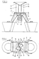
- the chopper on which FIGS. 1 and 2 are based has a housing which consists of a bowl-shaped base 1 with a flanged cover 2 and is accommodated on three legs 3. These rest with their upper end on the flange 4 of the lower housing part and can simply be held by the flange connection screws 5.
- the housing 1 consisting of bottom 1 with a flanged lid contains a chamber 6, in which a carrier disk 7 for a knife 8 is arranged, which is fastened by screws to the rear edge of an assigned passage slot 9 in the direction of rotation, overlapping on the carrier disk 7.
- the carrier disk 7 is received with a vertical axis on a shaft 10 of a motor 11 in the form of an electric motor suspended on the outside of the bottom 1 and arranged through the bottom 1, over which the carrier disk 7 passes.
- the carrier disk 7 can be centered by a shaft journal engaging in a central bore and fastened on the shaft 20 by a retaining screw 12 which can be screwed into a threaded blind hole in the shaft journal.
- the cover 2 is provided with a loading opening 13, which is gripped under by the carrier disk 7 and into which a loading shaft 14 has the same cross-section lower end is inserted.
- the tubular loading shaft 14 has a cross section that is constant over its entire length and is arranged with an axis perpendicular to the plane of the carrier plate 7.
- a funnel 15 is placed on the upper end of the feed chute 14 and prevents free access to the carrier disk 7.
- the loading opening 13 and, accordingly, also the loading shaft 14 have a cross-section which extends from the edge region of the carrier disk 7 beyond its center, ie the center of the carrier disk 7, and thus a large cross section, which is only slightly reduced compared to the disk surface.
- the surface of the carrier disk 7 is, as can best be seen from FIG. 2, largely used to close the feed chute 14.
- the feed opening 13 and the feed shaft 14 are provided with a radial circumferential indentation 16, on the rear flank of which in the direction of rotation that comminuting material comes to rest as a result of the rotational movement of the carrier disk 7 and the counterhold 17, which is accordingly stationary, acts.
- the feed shaft 14 arranged with a vertical axis can be designed as a pipe section.
- the feed shaft 14 is, as can best be seen from FIG. 2, placed on the cover 2 of the housing in such a way that the center of the circle is opaque to the axis of the carrier disk 7.
- the depth of the indentation 16 is chosen so that the stationary counter-holder 17 thus formed is at least the length of the hereby acting knife 8 has a corresponding radial extent.
- the rear flank of the indentation 16 forming the stationary counter-holder 12 can have a radial course with respect to the disk axis.
- the rear flank of the recess 16 forming the counter-holder 10 is pivoted by about 3 ° to 5 ° with respect to a radial beam, the radially inner end of the counter-holder 7 being pivoted in the direction of rotation of the carrier disk 7 and the radially outer end counter to the direction of rotation.
- the chopped material passes through the passage slot 9 and is through to the underside of the carrier plate be 7 attached wing 18 ejected via a stationary ejector 17 associated with the ejection opening 19 of the housing.
- the ejection opening 19 is arranged such that a deflection-free ejection takes place in the plan view.
- the arrangement is such that, in the top view, the solder on the passage surface of the ejection opening 19 is approximately perpendicular to the rear flank of the indentation 16 forming the stationary counter-holder 17.
- the ejection opening 19 is formed by a recess in the trough-shaped bottom 1 arranged with an inclined surface.
- the bottom 1 and the cover 2 extending over it can be provided in the region of the ejection opening 19 with a downward deflection of the material causing deflection plates.
- the base 1 and the cover 2 are provided with edge claws 20 delimiting the ejection opening 19, to which an ejection chute 21 is attached in such a way that its axis is inclined downwards outwards. With the help of the discharge chute 21, the discharge jet can be directed into a collecting container of the type indicated at 22.
- a centrally arranged deflecting body 23 is placed on the latter. This can easily be held by means of the screw 12 and is provided with a central hole for this purpose.
- the deflector 23 can be designed as an L-bw. Be U-shaped bracket.
- the deflector body 23, as can best be seen from FIG. 5, is designed as a crown-shaped molded part with a plurality of tines 24 molded onto the circumference. These provide so much Unrest in the area of the disc center that the material entered into the loading shaft 14 is reliably thrown radially outward into the area of the knife 8.
- the radially inner edge of the knife 8 arranged here lies against an adjacent flank of the deflecting body 23.
- the depth of the indentation 16 is chosen so that the largest diameter of the deflector 23 corresponds to twice the distance of the inner buckling edge from the center of the carrier disk 7, so that the material input into the loading shaft 14 is reliably comminuted.
- FIGS. 3 and 4 differs from the embodiment according to FIGS. 1 and 2 described above in that the loading chute 14 has two diametrically opposed indentations 16 and the housing 2 has diametrically opposed ejection openings 19 assigned to these two indentations 16 and that Carrier disc 7 is occupied by two diametrically opposed knives 8.
- the chopper on which FIGS. 3 and 4 are based also has a housing consisting of a base 1 and a flanged-on cover 2 with a chamber 6 for receiving a support disk which rotates about a vertical axis and which is received on the shaft 10 of a motor 1 attached to the base 1 and which extends through the base 1 7.
- a centrally located, crown-shaped deflector Body 23 of the type shown in Figure 5 is provided, which rests with mutually opposite flanks on the inner ends of the two opposing knives 8, each of which overlaps an assigned passage slot 9.
- the carrier disk 7 accordingly also has two passage slots 9.
- the knives 8 can be arranged exactly radially.
- the two knives 8 are slightly displaced forward in the direction of rotation of the carrier disk 7 in relation to two radial jets offset by 180 ° with respect to one another.
- the same also applies to the passage slots 9, which can have an advantageous effect on the stability of the carrier disk 7.
- the loading shaft 14 here has a prismatic cross section with the two indentations 16 and is placed on the cover 2 with a perpendicular axis concentric with the axis of the carrier disk 7.
- the feed chute 14, which is prismatic in cross section, can be composed of two molded articles having a W-shaped configuration.
- the smallest clear width of the prismatic loading chute 14 corresponds approximately to the largest diameter of the deflecting body 23 placed on the carrier disk 7. This diameter is chosen so that the clear width of the feed chute 14 is also so large in the area of the two indentations 16 that No constipation.
- the length of the knives 8 and the stationary counterholders 17 associated therewith in the region of the indentations 16 is somewhat shortened compared to the design with only one knife.
- the arrangement can be such that, in the top view, the solder on the passage surface of the ejection opening 19 is perpendicular to the flank of the adjacent indentation 16 forming the respectively assigned counter-holder.
- An ejection chute 21 which is inclined downward is placed on each ejection opening 19 in the same way as in the embodiment according to FIGS. 1 and 2.
- the use of a plurality of ejection openings 19 results in an increase in the total ejection area, which has an advantageous effect on the prevention of blockages on the ejection side.
Landscapes
- Engineering & Computer Science (AREA)
- Food Science & Technology (AREA)
- Crushing And Pulverization Processes (AREA)
- Processing Of Solid Wastes (AREA)
- Soil Working Implements (AREA)
- Harvesting Machines For Specific Crops (AREA)
Priority Applications (1)
| Application Number | Priority Date | Filing Date | Title |
|---|---|---|---|
| AT87108780T ATE52203T1 (de) | 1986-06-26 | 1987-06-19 | Vorrichtung zum haeckseln von gartenabfaellen. |
Applications Claiming Priority (2)
| Application Number | Priority Date | Filing Date | Title |
|---|---|---|---|
| DE3621418 | 1986-06-26 | ||
| DE19863621418 DE3621418A1 (de) | 1986-06-26 | 1986-06-26 | Vorrichtung zum haeckseln von gartenabfaellen |
Publications (3)
| Publication Number | Publication Date |
|---|---|
| EP0251060A2 true EP0251060A2 (fr) | 1988-01-07 |
| EP0251060A3 EP0251060A3 (en) | 1988-10-05 |
| EP0251060B1 EP0251060B1 (fr) | 1990-04-25 |
Family
ID=6303761
Family Applications (1)
| Application Number | Title | Priority Date | Filing Date |
|---|---|---|---|
| EP87108780A Expired - Lifetime EP0251060B1 (fr) | 1986-06-26 | 1987-06-19 | Dispositif déchiqueteur pour déchets de jardin |
Country Status (7)
| Country | Link |
|---|---|
| US (1) | US4778117A (fr) |
| EP (1) | EP0251060B1 (fr) |
| JP (1) | JPS637853A (fr) |
| AT (1) | ATE52203T1 (fr) |
| AU (1) | AU589096B2 (fr) |
| CA (1) | CA1293234C (fr) |
| DE (1) | DE3621418A1 (fr) |
Cited By (7)
| Publication number | Priority date | Publication date | Assignee | Title |
|---|---|---|---|---|
| EP0505702A1 (fr) * | 1991-03-27 | 1992-09-30 | Crones & Co. Gmbh | Broyeur de déchets de jardin avec enceinte contenant des couteaux plats ainsi que des couteaux de prébroyage à entraîner en rotation |
| US5267697A (en) * | 1992-11-30 | 1993-12-07 | Frank Holecz | Garden shredder apparatus |
| GB2259872B (en) * | 1991-09-10 | 1995-05-03 | Garden Way Inc | Apparatus for converting tree limits and the like into small pieces of debris |
| GB2283184A (en) * | 1993-10-29 | 1995-05-03 | John Walmsley | Apparatus for processing a solid material |
| FR2723326A1 (fr) * | 1994-08-04 | 1996-02-09 | Lescha Maschf Gmbh | Appareil pour hacher des dechets de jardin |
| CN104174463A (zh) * | 2014-08-15 | 2014-12-03 | 湖南三德科技股份有限公司 | 自沉降式制样粉碎机 |
| CN121266674A (zh) * | 2025-12-09 | 2026-01-06 | 浙江兴盛机械有限公司 | 一种多功能立式研磨泵 |
Families Citing this family (34)
| Publication number | Priority date | Publication date | Assignee | Title |
|---|---|---|---|---|
| DE3722339A1 (de) * | 1987-07-07 | 1989-01-19 | Crones & Co Gmbh | Motorisch angetriebener gartenabfallhaecksler |
| US4955548A (en) * | 1989-10-13 | 1990-09-11 | Industrial Equipment & Engineering Company | Method and apparatus for comminuting cremation remains |
| US5018672A (en) * | 1989-11-27 | 1991-05-28 | Kathcon, Inc. | Organic material reduction apparatus |
| US5085375A (en) * | 1990-12-21 | 1992-02-04 | Cotter & Company | Leaf mulcher |
| DE9110978U1 (de) * | 1991-09-04 | 1993-01-14 | Viking-Umwelttechnik GmbH, Kufstein | Zerkleinerungsvorrichtung |
| US5207152A (en) * | 1991-10-28 | 1993-05-04 | Wettlaufer Dale E | Compact juice machine |
| DE9215679U1 (de) * | 1992-11-18 | 1994-04-21 | Telsnig, Adolf, 34125 Kassel | Häcksler, insbesondere für Haus- und Gartenabfälle |
| US5323927A (en) * | 1993-08-18 | 1994-06-28 | Viking-Umwelttechnik Gmbh | Receptacle means |
| DE4329799A1 (de) * | 1993-09-03 | 1995-03-09 | Lescha Maschf Gmbh | Vorrichtung zum Häckseln von Gartenabfällen |
| US5474241A (en) * | 1994-05-17 | 1995-12-12 | Kennedy; Brian L. | Portable apparatus for creating mulch |
| US5642864A (en) * | 1994-11-18 | 1997-07-01 | Simplicity Manufacturing, Inc. | Chipper vacuum shredder system and apparatus |
| WO2000013797A1 (fr) * | 1998-09-03 | 2000-03-16 | Bartlem Pty. Ltd. | Dechiqueteuse de residus horticoles |
| US6394373B1 (en) * | 2000-06-30 | 2002-05-28 | Morris & Associates | Sloped cutter knives on tube-type ice maker |
| DE60319313T2 (de) * | 2002-08-30 | 2009-03-26 | Robert Bosch Gmbh | Apparat zum Zerhacken |
| US7431231B1 (en) | 2006-12-06 | 2008-10-07 | Tong Myong Saiki | Portable shredding device |
| US7909276B2 (en) * | 2007-02-23 | 2011-03-22 | Monsanto Technology Llc | Agricultural sample grinder |
| US8122697B1 (en) | 2009-03-27 | 2012-02-28 | Leaf Harvest, LLC | Leaf cutting apparatus |
| CN101992144B (zh) * | 2009-08-20 | 2012-11-21 | 苏州宝时得电动工具有限公司 | 园艺粉碎机 |
| US8596565B2 (en) | 2011-05-18 | 2013-12-03 | 105766 Canada Inc. | Leaf stripper |
| US11344052B2 (en) | 2014-06-11 | 2022-05-31 | Goodnature Products, Inc. | Partial or whole food hopper, grinder and cold press counter-top juicing machine, system and method |
| CN106660290A (zh) | 2014-06-11 | 2017-05-10 | 戴尔·韦特劳佛 | 榨汁装置及其方法 |
| CN106583418A (zh) * | 2016-12-08 | 2017-04-26 | 成都格瑞思文化传播有限公司 | 一种生活垃圾处理器 |
| US10440891B2 (en) * | 2017-07-18 | 2019-10-15 | Peter Ryan Hall | Apparatus for separating plant material from a harvested plant |
| US10645966B2 (en) | 2017-11-30 | 2020-05-12 | Goodnature Products, Inc. | Apparatus for grinding food |
| CN109225506A (zh) * | 2018-08-22 | 2019-01-18 | 郑州仁宏医药科技有限公司 | 一种新型的制药用破碎设备 |
| CN109699513B (zh) * | 2019-03-06 | 2021-03-02 | 杭州腾鸿农业开发有限公司 | 一种智能化喂料养猪设备 |
| WO2020242897A1 (fr) | 2019-05-24 | 2020-12-03 | Goodnature Products, Inc. | Dispositifs d'extraction de jus dotés d'un ensemble broyeur amovible |
| USD918656S1 (en) | 2019-09-12 | 2021-05-11 | Goodnature Products, Inc. | Pusher |
| USD914464S1 (en) | 2019-09-12 | 2021-03-30 | Goodnature Products, Inc. | Press box |
| USD914465S1 (en) | 2019-09-12 | 2021-03-30 | Goodnature Products, Inc. | Juicing device |
| CN111925242A (zh) * | 2020-08-03 | 2020-11-13 | 马鞍山科邦生态肥有限公司 | 一种可快速粉碎的微生物肥料生产用发酵装置 |
| USD916565S1 (en) | 2020-09-15 | 2021-04-20 | Goodnature Products, Inc. | Juicing device |
| USD915156S1 (en) | 2020-09-15 | 2021-04-06 | Goodnature Products, Inc. | Press box |
| US20230218101A1 (en) | 2022-01-13 | 2023-07-13 | Goodnature Products, Inc. | Juicing devices and methods |
Family Cites Families (6)
| Publication number | Priority date | Publication date | Assignee | Title |
|---|---|---|---|---|
| NL6615139A (fr) * | 1966-10-26 | 1968-04-29 | ||
| US3508715A (en) * | 1967-10-17 | 1970-04-28 | Ronson Corp | Ice chipper |
| DE3209873A1 (de) * | 1982-03-18 | 1983-09-29 | Leonhard Schmid Kg, 8900 Augsburg | Abfall-zerkleinerer, insbesondere fuer gartenabfaelle |
| DE3232504A1 (de) * | 1982-09-01 | 1984-03-01 | Ismar GmbH, 5000 Köln | Maschine zum zerkleinern von baeckereiprodukten wie restbrot und dergleichen |
| DE3324274A1 (de) * | 1983-07-06 | 1985-01-24 | Leonhard Schmid Kg, 8900 Augsburg | Haeckselgeraet fuer gartenabfaelle u.dgl. |
| US4595148A (en) * | 1983-10-03 | 1986-06-17 | Mcculloch Corporation | Machine for comminuting waste material |
-
1986
- 1986-06-26 DE DE19863621418 patent/DE3621418A1/de active Granted
-
1987
- 1987-06-08 CA CA000539122A patent/CA1293234C/fr not_active Expired - Lifetime
- 1987-06-11 US US07/060,610 patent/US4778117A/en not_active Expired - Fee Related
- 1987-06-19 AT AT87108780T patent/ATE52203T1/de not_active IP Right Cessation
- 1987-06-19 EP EP87108780A patent/EP0251060B1/fr not_active Expired - Lifetime
- 1987-06-23 JP JP62157453A patent/JPS637853A/ja active Pending
- 1987-06-26 AU AU74733/87A patent/AU589096B2/en not_active Ceased
Cited By (8)
| Publication number | Priority date | Publication date | Assignee | Title |
|---|---|---|---|---|
| EP0505702A1 (fr) * | 1991-03-27 | 1992-09-30 | Crones & Co. Gmbh | Broyeur de déchets de jardin avec enceinte contenant des couteaux plats ainsi que des couteaux de prébroyage à entraîner en rotation |
| GB2259872B (en) * | 1991-09-10 | 1995-05-03 | Garden Way Inc | Apparatus for converting tree limits and the like into small pieces of debris |
| US5267697A (en) * | 1992-11-30 | 1993-12-07 | Frank Holecz | Garden shredder apparatus |
| GB2283184A (en) * | 1993-10-29 | 1995-05-03 | John Walmsley | Apparatus for processing a solid material |
| GB2283184B (en) * | 1993-10-29 | 1997-11-12 | John Walmsley | Apparatus for processing a solid material |
| FR2723326A1 (fr) * | 1994-08-04 | 1996-02-09 | Lescha Maschf Gmbh | Appareil pour hacher des dechets de jardin |
| CN104174463A (zh) * | 2014-08-15 | 2014-12-03 | 湖南三德科技股份有限公司 | 自沉降式制样粉碎机 |
| CN121266674A (zh) * | 2025-12-09 | 2026-01-06 | 浙江兴盛机械有限公司 | 一种多功能立式研磨泵 |
Also Published As
| Publication number | Publication date |
|---|---|
| US4778117A (en) | 1988-10-18 |
| EP0251060A3 (en) | 1988-10-05 |
| CA1293234C (fr) | 1991-12-17 |
| ATE52203T1 (de) | 1990-05-15 |
| DE3621418A1 (de) | 1988-01-14 |
| EP0251060B1 (fr) | 1990-04-25 |
| AU589096B2 (en) | 1989-09-28 |
| JPS637853A (ja) | 1988-01-13 |
| DE3621418C2 (fr) | 1990-05-23 |
| AU7473387A (en) | 1988-01-07 |
Similar Documents
| Publication | Publication Date | Title |
|---|---|---|
| EP0251060B1 (fr) | Dispositif déchiqueteur pour déchets de jardin | |
| EP1065963B1 (fr) | Ecran en forme de cloche destine a un appareil menager, notamment un mixeur ou un batteur | |
| CH659563A5 (de) | Vorrichtung zum maehen von erntegut. | |
| DE2649305B2 (de) | Lochscheibe für einen Fleischwolf | |
| EP0222121A1 (fr) | Outil pour couper et mélanger pour robot de cuisine électrique | |
| DE3722339A1 (de) | Motorisch angetriebener gartenabfallhaecksler | |
| WO2000047066A1 (fr) | Dispositif destine a dechiqueter des substances organiques | |
| DE3236121A1 (de) | Vorrichtung zum bereitstellen und ausgeben von viehfutter | |
| EP0598306B1 (fr) | Déchiqueteur en particulier pour déchets ménagers et débris de jardin | |
| EP0505702B1 (fr) | Broyeur de déchets de jardin avec enceinte contenant des couteaux plats ainsi que des couteaux de prébroyage à entraîner en rotation | |
| DE3607021A1 (de) | Maschine zum zerkleinern von holzstuecken | |
| DE3226677A1 (de) | Vorrichtung zum zerkleinern von gut | |
| DE8131506U1 (de) | Zerkleinerungseinrichtung | |
| DE2256951A1 (de) | Schnitzelgeraet fuer haushalt-kuechenmaschinen | |
| DE3312378A1 (de) | Abfallbeseitigungsvorrichtung | |
| DE3612997A1 (de) | Maschine zum zerkleinern von holzstuecken und dergleichen | |
| DE19548883C2 (de) | Langsamlaufender Gartenhäcksler | |
| DE3503904C2 (fr) | ||
| EP0089571B1 (fr) | Désintégrateur du bois | |
| DE3118518A1 (de) | "abfall-zerkleinerer, insbesondere fuer gartenabfaelle" | |
| DE4111310C2 (de) | Mahlaufsatz für Haushaltsküchenmaschinen | |
| DE3219182C2 (de) | Messervorrichtung für Gartenhäcksler | |
| DE4142593C2 (de) | Häcksler mit einem Messerteller-Aufsatz | |
| DE9307422U1 (de) | Zerkleinerungsvorrichtung für Abfälle | |
| DE102013217690A1 (de) | Komponente eines Küchengeräts |
Legal Events
| Date | Code | Title | Description |
|---|---|---|---|
| PUAI | Public reference made under article 153(3) epc to a published international application that has entered the european phase |
Free format text: ORIGINAL CODE: 0009012 |
|
| AK | Designated contracting states |
Kind code of ref document: A2 Designated state(s): AT FR GB IT |
|
| PUAL | Search report despatched |
Free format text: ORIGINAL CODE: 0009013 |
|
| AK | Designated contracting states |
Kind code of ref document: A3 Designated state(s): AT FR GB IT |
|
| 17P | Request for examination filed |
Effective date: 19890201 |
|
| 17Q | First examination report despatched |
Effective date: 19890914 |
|
| GRAA | (expected) grant |
Free format text: ORIGINAL CODE: 0009210 |
|
| AK | Designated contracting states |
Kind code of ref document: B1 Designated state(s): AT FR GB IT |
|
| REF | Corresponds to: |
Ref document number: 52203 Country of ref document: AT Date of ref document: 19900515 Kind code of ref document: T |
|
| GBT | Gb: translation of ep patent filed (gb section 77(6)(a)/1977) | ||
| ITF | It: translation for a ep patent filed | ||
| ET | Fr: translation filed | ||
| PLBE | No opposition filed within time limit |
Free format text: ORIGINAL CODE: 0009261 |
|
| STAA | Information on the status of an ep patent application or granted ep patent |
Free format text: STATUS: NO OPPOSITION FILED WITHIN TIME LIMIT |
|
| 26N | No opposition filed | ||
| ITTA | It: last paid annual fee | ||
| PGFP | Annual fee paid to national office [announced via postgrant information from national office to epo] |
Ref country code: GB Payment date: 19940418 Year of fee payment: 8 |
|
| PGFP | Annual fee paid to national office [announced via postgrant information from national office to epo] |
Ref country code: FR Payment date: 19940518 Year of fee payment: 8 |
|
| PGFP | Annual fee paid to national office [announced via postgrant information from national office to epo] |
Ref country code: AT Payment date: 19940519 Year of fee payment: 8 |
|
| PG25 | Lapsed in a contracting state [announced via postgrant information from national office to epo] |
Ref country code: GB Effective date: 19950619 Ref country code: AT Effective date: 19950619 |
|
| GBPC | Gb: european patent ceased through non-payment of renewal fee |
Effective date: 19950619 |
|
| PG25 | Lapsed in a contracting state [announced via postgrant information from national office to epo] |
Ref country code: FR Effective date: 19960229 |
|
| REG | Reference to a national code |
Ref country code: FR Ref legal event code: ST |
|
| PG25 | Lapsed in a contracting state [announced via postgrant information from national office to epo] |
Ref country code: IT Free format text: LAPSE BECAUSE OF NON-PAYMENT OF DUE FEES;WARNING: LAPSES OF ITALIAN PATENTS WITH EFFECTIVE DATE BEFORE 2007 MAY HAVE OCCURRED AT ANY TIME BEFORE 2007. THE CORRECT EFFECTIVE DATE MAY BE DIFFERENT FROM THE ONE RECORDED. Effective date: 20050619 |