EP0251070A2 - Procédé et appareil de soudage par ultra-sons - Google Patents
Procédé et appareil de soudage par ultra-sons Download PDFInfo
- Publication number
- EP0251070A2 EP0251070A2 EP87108808A EP87108808A EP0251070A2 EP 0251070 A2 EP0251070 A2 EP 0251070A2 EP 87108808 A EP87108808 A EP 87108808A EP 87108808 A EP87108808 A EP 87108808A EP 0251070 A2 EP0251070 A2 EP 0251070A2
- Authority
- EP
- European Patent Office
- Prior art keywords
- bonding
- drum
- travel path
- sonotrode
- anvil
- Prior art date
- Legal status (The legal status is an assumption and is not a legal conclusion. Google has not performed a legal analysis and makes no representation as to the accuracy of the status listed.)
- Withdrawn
Links
Images

Classifications
-
- B—PERFORMING OPERATIONS; TRANSPORTING
- B29—WORKING OF PLASTICS; WORKING OF SUBSTANCES IN A PLASTIC STATE IN GENERAL
- B29C—SHAPING OR JOINING OF PLASTICS; SHAPING OF MATERIAL IN A PLASTIC STATE, NOT OTHERWISE PROVIDED FOR; AFTER-TREATMENT OF THE SHAPED PRODUCTS, e.g. REPAIRING
- B29C65/00—Joining or sealing of preformed parts, e.g. welding of plastics materials; Apparatus therefor
- B29C65/78—Means for handling the parts to be joined, e.g. for making containers or hollow articles, e.g. means for handling sheets, plates, web-like materials, tubular articles, hollow articles or elements to be joined therewith; Means for discharging the joined articles from the joining apparatus
- B29C65/7858—Means for handling the parts to be joined, e.g. for making containers or hollow articles, e.g. means for handling sheets, plates, web-like materials, tubular articles, hollow articles or elements to be joined therewith; Means for discharging the joined articles from the joining apparatus characterised by the feeding movement of the parts to be joined
- B29C65/7879—Means for handling the parts to be joined, e.g. for making containers or hollow articles, e.g. means for handling sheets, plates, web-like materials, tubular articles, hollow articles or elements to be joined therewith; Means for discharging the joined articles from the joining apparatus characterised by the feeding movement of the parts to be joined said parts to be joined moving in a closed path, e.g. a rectangular path
- B29C65/7882—Means for handling the parts to be joined, e.g. for making containers or hollow articles, e.g. means for handling sheets, plates, web-like materials, tubular articles, hollow articles or elements to be joined therewith; Means for discharging the joined articles from the joining apparatus characterised by the feeding movement of the parts to be joined said parts to be joined moving in a closed path, e.g. a rectangular path said parts to be joined moving in a circular path
- B29C65/7885—Rotary turret joining machines, i.e. having several joining tools moving around an axis
-
- B—PERFORMING OPERATIONS; TRANSPORTING
- B29—WORKING OF PLASTICS; WORKING OF SUBSTANCES IN A PLASTIC STATE IN GENERAL
- B29C—SHAPING OR JOINING OF PLASTICS; SHAPING OF MATERIAL IN A PLASTIC STATE, NOT OTHERWISE PROVIDED FOR; AFTER-TREATMENT OF THE SHAPED PRODUCTS, e.g. REPAIRING
- B29C65/00—Joining or sealing of preformed parts, e.g. welding of plastics materials; Apparatus therefor
- B29C65/02—Joining or sealing of preformed parts, e.g. welding of plastics materials; Apparatus therefor by heating, with or without pressure
- B29C65/08—Joining or sealing of preformed parts, e.g. welding of plastics materials; Apparatus therefor by heating, with or without pressure using ultrasonic vibrations
- B29C65/083—Joining or sealing of preformed parts, e.g. welding of plastics materials; Apparatus therefor by heating, with or without pressure using ultrasonic vibrations using a rotary sonotrode or a rotary anvil
- B29C65/085—Joining or sealing of preformed parts, e.g. welding of plastics materials; Apparatus therefor by heating, with or without pressure using ultrasonic vibrations using a rotary sonotrode or a rotary anvil using a rotary sonotrode
-
- B—PERFORMING OPERATIONS; TRANSPORTING
- B29—WORKING OF PLASTICS; WORKING OF SUBSTANCES IN A PLASTIC STATE IN GENERAL
- B29C—SHAPING OR JOINING OF PLASTICS; SHAPING OF MATERIAL IN A PLASTIC STATE, NOT OTHERWISE PROVIDED FOR; AFTER-TREATMENT OF THE SHAPED PRODUCTS, e.g. REPAIRING
- B29C66/00—General aspects of processes or apparatus for joining preformed parts
- B29C66/01—General aspects dealing with the joint area or with the area to be joined
- B29C66/05—Particular design of joint configurations
- B29C66/10—Particular design of joint configurations particular design of the joint cross-sections
- B29C66/11—Joint cross-sections comprising a single joint-segment, i.e. one of the parts to be joined comprising a single joint-segment in the joint cross-section
- B29C66/112—Single lapped joints
- B29C66/1122—Single lap to lap joints, i.e. overlap joints
-
- B—PERFORMING OPERATIONS; TRANSPORTING
- B29—WORKING OF PLASTICS; WORKING OF SUBSTANCES IN A PLASTIC STATE IN GENERAL
- B29C—SHAPING OR JOINING OF PLASTICS; SHAPING OF MATERIAL IN A PLASTIC STATE, NOT OTHERWISE PROVIDED FOR; AFTER-TREATMENT OF THE SHAPED PRODUCTS, e.g. REPAIRING
- B29C66/00—General aspects of processes or apparatus for joining preformed parts
- B29C66/40—General aspects of joining substantially flat articles, e.g. plates, sheets or web-like materials; Making flat seams in tubular or hollow articles; Joining single elements to substantially flat surfaces
- B29C66/41—Joining substantially flat articles ; Making flat seams in tubular or hollow articles
- B29C66/43—Joining a relatively small portion of the surface of said articles
-
- B—PERFORMING OPERATIONS; TRANSPORTING
- B29—WORKING OF PLASTICS; WORKING OF SUBSTANCES IN A PLASTIC STATE IN GENERAL
- B29C—SHAPING OR JOINING OF PLASTICS; SHAPING OF MATERIAL IN A PLASTIC STATE, NOT OTHERWISE PROVIDED FOR; AFTER-TREATMENT OF THE SHAPED PRODUCTS, e.g. REPAIRING
- B29C66/00—General aspects of processes or apparatus for joining preformed parts
- B29C66/80—General aspects of machine operations or constructions and parts thereof
- B29C66/81—General aspects of the pressing elements, i.e. the elements applying pressure on the parts to be joined in the area to be joined, e.g. the welding jaws or clamps
- B29C66/814—General aspects of the pressing elements, i.e. the elements applying pressure on the parts to be joined in the area to be joined, e.g. the welding jaws or clamps characterised by the design of the pressing elements, e.g. of the welding jaws or clamps
- B29C66/8145—General aspects of the pressing elements, i.e. the elements applying pressure on the parts to be joined in the area to be joined, e.g. the welding jaws or clamps characterised by the design of the pressing elements, e.g. of the welding jaws or clamps characterised by the constructional aspects of the pressing elements, e.g. of the welding jaws or clamps
- B29C66/81463—General aspects of the pressing elements, i.e. the elements applying pressure on the parts to be joined in the area to be joined, e.g. the welding jaws or clamps characterised by the design of the pressing elements, e.g. of the welding jaws or clamps characterised by the constructional aspects of the pressing elements, e.g. of the welding jaws or clamps comprising a plurality of single pressing elements, e.g. a plurality of sonotrodes, or comprising a plurality of single counter-pressing elements, e.g. a plurality of anvils, said plurality of said single elements being suitable for making a single joint
-
- B—PERFORMING OPERATIONS; TRANSPORTING
- B29—WORKING OF PLASTICS; WORKING OF SUBSTANCES IN A PLASTIC STATE IN GENERAL
- B29C—SHAPING OR JOINING OF PLASTICS; SHAPING OF MATERIAL IN A PLASTIC STATE, NOT OTHERWISE PROVIDED FOR; AFTER-TREATMENT OF THE SHAPED PRODUCTS, e.g. REPAIRING
- B29C66/00—General aspects of processes or apparatus for joining preformed parts
- B29C66/80—General aspects of machine operations or constructions and parts thereof
- B29C66/81—General aspects of the pressing elements, i.e. the elements applying pressure on the parts to be joined in the area to be joined, e.g. the welding jaws or clamps
- B29C66/816—General aspects of the pressing elements, i.e. the elements applying pressure on the parts to be joined in the area to be joined, e.g. the welding jaws or clamps characterised by the mounting of the pressing elements, e.g. of the welding jaws or clamps
- B29C66/8161—General aspects of the pressing elements, i.e. the elements applying pressure on the parts to be joined in the area to be joined, e.g. the welding jaws or clamps characterised by the mounting of the pressing elements, e.g. of the welding jaws or clamps said pressing elements being supported or backed-up by springs or by resilient material
-
- B—PERFORMING OPERATIONS; TRANSPORTING
- B29—WORKING OF PLASTICS; WORKING OF SUBSTANCES IN A PLASTIC STATE IN GENERAL
- B29C—SHAPING OR JOINING OF PLASTICS; SHAPING OF MATERIAL IN A PLASTIC STATE, NOT OTHERWISE PROVIDED FOR; AFTER-TREATMENT OF THE SHAPED PRODUCTS, e.g. REPAIRING
- B29C66/00—General aspects of processes or apparatus for joining preformed parts
- B29C66/80—General aspects of machine operations or constructions and parts thereof
- B29C66/82—Pressure application arrangements, e.g. transmission or actuating mechanisms for joining tools or clamps
- B29C66/822—Transmission mechanisms
- B29C66/8223—Worm or spindle mechanisms
-
- B—PERFORMING OPERATIONS; TRANSPORTING
- B29—WORKING OF PLASTICS; WORKING OF SUBSTANCES IN A PLASTIC STATE IN GENERAL
- B29C—SHAPING OR JOINING OF PLASTICS; SHAPING OF MATERIAL IN A PLASTIC STATE, NOT OTHERWISE PROVIDED FOR; AFTER-TREATMENT OF THE SHAPED PRODUCTS, e.g. REPAIRING
- B29C66/00—General aspects of processes or apparatus for joining preformed parts
- B29C66/80—General aspects of machine operations or constructions and parts thereof
- B29C66/82—Pressure application arrangements, e.g. transmission or actuating mechanisms for joining tools or clamps
- B29C66/822—Transmission mechanisms
- B29C66/8226—Cam mechanisms; Wedges; Eccentric mechanisms
- B29C66/82263—Follower pin or roller cooperating with a groove
-
- B—PERFORMING OPERATIONS; TRANSPORTING
- B29—WORKING OF PLASTICS; WORKING OF SUBSTANCES IN A PLASTIC STATE IN GENERAL
- B29C—SHAPING OR JOINING OF PLASTICS; SHAPING OF MATERIAL IN A PLASTIC STATE, NOT OTHERWISE PROVIDED FOR; AFTER-TREATMENT OF THE SHAPED PRODUCTS, e.g. REPAIRING
- B29C66/00—General aspects of processes or apparatus for joining preformed parts
- B29C66/80—General aspects of machine operations or constructions and parts thereof
- B29C66/83—General aspects of machine operations or constructions and parts thereof characterised by the movement of the joining or pressing tools
- B29C66/832—Reciprocating joining or pressing tools
- B29C66/8322—Joining or pressing tools reciprocating along one axis
-
- B—PERFORMING OPERATIONS; TRANSPORTING
- B29—WORKING OF PLASTICS; WORKING OF SUBSTANCES IN A PLASTIC STATE IN GENERAL
- B29C—SHAPING OR JOINING OF PLASTICS; SHAPING OF MATERIAL IN A PLASTIC STATE, NOT OTHERWISE PROVIDED FOR; AFTER-TREATMENT OF THE SHAPED PRODUCTS, e.g. REPAIRING
- B29C66/00—General aspects of processes or apparatus for joining preformed parts
- B29C66/80—General aspects of machine operations or constructions and parts thereof
- B29C66/83—General aspects of machine operations or constructions and parts thereof characterised by the movement of the joining or pressing tools
- B29C66/834—General aspects of machine operations or constructions and parts thereof characterised by the movement of the joining or pressing tools moving with the parts to be joined
- B29C66/8351—Jaws mounted on rollers, cylinders, drums, bands, belts or chains; Flying jaws
- B29C66/83511—Jaws mounted on rollers, cylinders, drums, bands, belts or chains; Flying jaws jaws mounted on rollers, cylinders or drums
- B29C66/83517—Jaws mounted on rollers, cylinders, drums, bands, belts or chains; Flying jaws jaws mounted on rollers, cylinders or drums said rollers, cylinders or drums being hollow
-
- B—PERFORMING OPERATIONS; TRANSPORTING
- B29—WORKING OF PLASTICS; WORKING OF SUBSTANCES IN A PLASTIC STATE IN GENERAL
- B29C—SHAPING OR JOINING OF PLASTICS; SHAPING OF MATERIAL IN A PLASTIC STATE, NOT OTHERWISE PROVIDED FOR; AFTER-TREATMENT OF THE SHAPED PRODUCTS, e.g. REPAIRING
- B29C66/00—General aspects of processes or apparatus for joining preformed parts
- B29C66/70—General aspects of processes or apparatus for joining preformed parts characterised by the composition, physical properties or the structure of the material of the parts to be joined; Joining with non-plastics material
- B29C66/73—General aspects of processes or apparatus for joining preformed parts characterised by the composition, physical properties or the structure of the material of the parts to be joined; Joining with non-plastics material characterised by the intensive physical properties of the material of the parts to be joined, by the optical properties of the material of the parts to be joined, by the extensive physical properties of the parts to be joined, by the state of the material of the parts to be joined or by the material of the parts to be joined being a thermoplastic or a thermoset
- B29C66/739—General aspects of processes or apparatus for joining preformed parts characterised by the composition, physical properties or the structure of the material of the parts to be joined; Joining with non-plastics material characterised by the intensive physical properties of the material of the parts to be joined, by the optical properties of the material of the parts to be joined, by the extensive physical properties of the parts to be joined, by the state of the material of the parts to be joined or by the material of the parts to be joined being a thermoplastic or a thermoset characterised by the material of the parts to be joined being a thermoplastic or a thermoset
- B29C66/7392—General aspects of processes or apparatus for joining preformed parts characterised by the composition, physical properties or the structure of the material of the parts to be joined; Joining with non-plastics material characterised by the intensive physical properties of the material of the parts to be joined, by the optical properties of the material of the parts to be joined, by the extensive physical properties of the parts to be joined, by the state of the material of the parts to be joined or by the material of the parts to be joined being a thermoplastic or a thermoset characterised by the material of the parts to be joined being a thermoplastic or a thermoset characterised by the material of at least one of the parts being a thermoplastic
- B29C66/73921—General aspects of processes or apparatus for joining preformed parts characterised by the composition, physical properties or the structure of the material of the parts to be joined; Joining with non-plastics material characterised by the intensive physical properties of the material of the parts to be joined, by the optical properties of the material of the parts to be joined, by the extensive physical properties of the parts to be joined, by the state of the material of the parts to be joined or by the material of the parts to be joined being a thermoplastic or a thermoset characterised by the material of the parts to be joined being a thermoplastic or a thermoset characterised by the material of at least one of the parts being a thermoplastic characterised by the materials of both parts being thermoplastics
-
- B—PERFORMING OPERATIONS; TRANSPORTING
- B29—WORKING OF PLASTICS; WORKING OF SUBSTANCES IN A PLASTIC STATE IN GENERAL
- B29C—SHAPING OR JOINING OF PLASTICS; SHAPING OF MATERIAL IN A PLASTIC STATE, NOT OTHERWISE PROVIDED FOR; AFTER-TREATMENT OF THE SHAPED PRODUCTS, e.g. REPAIRING
- B29C66/00—General aspects of processes or apparatus for joining preformed parts
- B29C66/80—General aspects of machine operations or constructions and parts thereof
- B29C66/82—Pressure application arrangements, e.g. transmission or actuating mechanisms for joining tools or clamps
- B29C66/822—Transmission mechanisms
- B29C66/8226—Cam mechanisms; Wedges; Eccentric mechanisms
- B29C66/82265—Eccentric mechanisms
-
- B—PERFORMING OPERATIONS; TRANSPORTING
- B29—WORKING OF PLASTICS; WORKING OF SUBSTANCES IN A PLASTIC STATE IN GENERAL
- B29C—SHAPING OR JOINING OF PLASTICS; SHAPING OF MATERIAL IN A PLASTIC STATE, NOT OTHERWISE PROVIDED FOR; AFTER-TREATMENT OF THE SHAPED PRODUCTS, e.g. REPAIRING
- B29C66/00—General aspects of processes or apparatus for joining preformed parts
- B29C66/80—General aspects of machine operations or constructions and parts thereof
- B29C66/84—Specific machine types or machines suitable for specific applications
- B29C66/851—Bag or container making machines
- B29C66/8511—Bag making machines
-
- B—PERFORMING OPERATIONS; TRANSPORTING
- B29—WORKING OF PLASTICS; WORKING OF SUBSTANCES IN A PLASTIC STATE IN GENERAL
- B29L—INDEXING SCHEME ASSOCIATED WITH SUBCLASS B29C, RELATING TO PARTICULAR ARTICLES
- B29L2031/00—Other particular articles
- B29L2031/712—Containers; Packaging elements or accessories, Packages
- B29L2031/7128—Bags, sacks, sachets
-
- Y—GENERAL TAGGING OF NEW TECHNOLOGICAL DEVELOPMENTS; GENERAL TAGGING OF CROSS-SECTIONAL TECHNOLOGIES SPANNING OVER SEVERAL SECTIONS OF THE IPC; TECHNICAL SUBJECTS COVERED BY FORMER USPC CROSS-REFERENCE ART COLLECTIONS [XRACs] AND DIGESTS
- Y10—TECHNICAL SUBJECTS COVERED BY FORMER USPC
- Y10T—TECHNICAL SUBJECTS COVERED BY FORMER US CLASSIFICATION
- Y10T156/00—Adhesive bonding and miscellaneous chemical manufacture
- Y10T156/17—Surface bonding means and/or assemblymeans with work feeding or handling means
- Y10T156/1702—For plural parts or plural areas of single part
- Y10T156/1712—Indefinite or running length work
- Y10T156/1737—Discontinuous, spaced area, and/or patterned pressing
-
- Y—GENERAL TAGGING OF NEW TECHNOLOGICAL DEVELOPMENTS; GENERAL TAGGING OF CROSS-SECTIONAL TECHNOLOGIES SPANNING OVER SEVERAL SECTIONS OF THE IPC; TECHNICAL SUBJECTS COVERED BY FORMER USPC CROSS-REFERENCE ART COLLECTIONS [XRACs] AND DIGESTS
- Y10—TECHNICAL SUBJECTS COVERED BY FORMER USPC
- Y10T—TECHNICAL SUBJECTS COVERED BY FORMER US CLASSIFICATION
- Y10T156/00—Adhesive bonding and miscellaneous chemical manufacture
- Y10T156/17—Surface bonding means and/or assemblymeans with work feeding or handling means
- Y10T156/1702—For plural parts or plural areas of single part
- Y10T156/1744—Means bringing discrete articles into assembled relationship
- Y10T156/1768—Means simultaneously conveying plural articles from a single source and serially presenting them to an assembly station
- Y10T156/1771—Turret or rotary drum-type conveyor
- Y10T156/1773—For flexible sheets
Definitions
- This invention generally relates to an apparatus and method for ultrasonically bonding a web, and more specifically relates to an improved apparatus and method wherein ultrasonic bonding dwell time on a moving material is not limited by the speed of the moving material relative to a stationary bonding station.
- U.S. Patent 4,193,833 to J. L. Young discloses the sealing of thermoplastic-coated paperboard cartons in which the carton layers are engaged on opposite surfaces by, respectively, a vibrating horn and an anvil, for a time sufficient to activate the thermoplastic sealant material.
- the anvil is movable with respect to the horn, between an inactive position (retracted), and an active position (engaged) in which the opposed work surfaces of the horn and anvil engage the carton layers in a clamping relationship while the horn is energized.
- U.S. Patent 4,490,199 to F.G. Dunning discloses an apparatus and method for splicing polymeric webs supported on an anvil, wherein an ultrasonic spot welder is slidably connected to support bars by bearing assemblies and is translated by a driving screw in a direction transverse of the web (column 5, line 68 to column 6, line 4) or axially of the web (column 4, line 66 to column 5, line 1).
- the welding horn is extended toward the web by a retraction cylinder assembly.
- ultrasonic bonding systems are known in which a sonotrode and its anvil are respectively reciprocated or rotated to meet on opposite sides of a moving continuous web to momentarily clamp the moving web between their respective bonding surfaces to ultrasonically bond it. It is known to mount a plurality of sonotrodes and cooperating anvils along the peripheries of respective counter-rotating drums positioned to form between the bonding surfaces thereof a nip through which one or more plies of moving web are passed. As the drums rotate, portions of the web or webs are clamped between the respective paired bonding surfaces as they pass through the nip in opposed, facing alignment with each other, on opposite sides of the web. With this arrangement, the dwell time of the paired bonding surfaces in bonding-effective alignment with each other is necessarily limited by the speed of travel of the web, which determines the peripheral linear speed of the drums.
- an apparatus for ultrasonically bonding a material comprising: at least one ultrasonic bonder comprising an anvil and a sonotrode each having a bonding surface; ultrasonic bonder transport means to continuously synchronously move the anvil and the sonotrode along respective closed travel paths which (1) are congruent to each other for a bonding zone segment thereof whereby the respective bonding surfaces of the anvil and the sonotrode are positioned in material-clamping facing alignment with each other during their movement along the bonding zone segment, and (2) which diverge from each other sufficiently to permit withdrawal of the (bonded) material, e.g., of a continuous web of material from between the travel paths; material transport means for introducing an ultrasonically bondable material into the bonding zone segment of the travel path for clamping thereof between the aligned bonding surfaces and for moving the clamped material through the bonding zone segment synchronously with the anvil and sonotrode; and means for
- the ultrasonic bonder transport means is configured so that one of the closed travel paths is an inner closed travel path and the other closed travel path is an outer closed travel path which encircles at least the bonding zone segment of the inner closed travel path.
- the bonder transport means is configured so that the planar projections of the closed travel paths are substantially concentric. In another aspect, the planar projection of at least one of the closed travel paths may be an oval. The term "planar projection" is defined hereinbelow.
- the bonder transport means is configured to axially translate the outer closed travel path relative to the inner closed travel path outside the bonding zone segment in order to provide sufficient clearance between the inner and outer travel paths for withdrawal of the material, e.g., a continuous web of the material, from therebetween.
- apparatus for ultrasonically bonding a material comprising: (a) a rotatable drum having an outer cylindrical surface; (b) means for rotating the drum; (c) means for introducing the material onto the outer cylindrical surface at a first position and for removing the material from the outer cylindrical surface at a second position circumferentially spaced from the first position, the outer cylindrical surface defining a travel path for the material from the first to the second positions; (d) at least one ultrasonic bonder comprising an anvil and a sonotrode each having a bonding surface; (e) ultrasonic bonder transport means to (1) orbit one of the anvil and sonotrode exteriorly of and synchronously with the drum and to orbit the other of the anvil and sonotrode interiorly of and synchronously with the drum so as to place their respective bonding surfaces into material-clamping facing alignment with each other at the outer cylindrical surface of the
- a plurality of ultrasonic bonders are disposed about the outer surface of the rotatable drum, the ultrasonic bonders are equally angularly spaced about the outer cylindrical surface of the drum, the travel path subtends an arc of from about 90° to about 300°, the bonding zone segment of the travel path subtends an arc of from about 30° to about 200°, the sonotrodes orbit interiorly of the drum and the anvils orbit exteriorly of the drum, and the anvils orbit interiorly of the drum and the sonotrodes orbit exteriorly of the drum.
- a method for ultrasonically bonding a material by means of at least one ultrasonic bonder comprising an anvil component and a sonotrode component, each having a bonding surface
- the method comprising: continuously synchronously moving the anvil and the sonotrode components along respective closed travel paths which are congruent to each other for a bonding zone segment thereof and maintaining the respective bonding surfaces of the anvil and the sonotrode in material-clamping, facing alignment with each other during their travel through said bonding zone segment; introducing an ultrasonically bondable material, e.g., a continuous web of material, into the bonding zone segment of the travel path, clamping the material be tween the aligned bonding surfaces and moving the clamped material through the bonding zone segment synchronously with the anvil and sonotrode; energizing the sonotrode in the bonding zone segment to emit ultrasonic vibrations while the anvil and sonotrode bonding surfaces are clamp
- Other method aspects of the invention include method aspects corresponding to the above-described apparatus aspects, e.g., moving the ultrasonic bonding components about outer and inner closed travel paths which may be concentric, etc.
- the term "sonotrode” will be understood to mean an ultrasonic bonding device to which energy may be applied to generate ultrasonic vibrations transmittable to an ultrasonically bondable material clamped between a bonding surface of the sonotrode and a bonding surface of a suitable anvil therefor.
- the sonotrode and the anvil thus comprise respective components of an ultrasonic bonding means, sometimes herein and in the claims referred to as an ultrasonic bonder.
- the present invention employs ultrasonic bonding means, i.e., one or more ultrasonic bonders, each comprising an anvil component and a sonotrode component and having a bonding surface.
- ultrasonic bonding means i.e., one or more ultrasonic bonders, each comprising an anvil component and a sonotrode component and having a bonding surface.
- one of the anvil and sonotrode ultrasonic bonding means is synchronously orbited interiorly of a drum or the like and radially positioned to present its bonding surface at or adjacent the outer cylindrical surface of the drum (e.g., through an opening therein) during rotation thereof along a bonding zone segment of the travel path of the drum.
- the other ultrasonic bonding means is synchronously orbited exteriorly of the drum to present its bonding surface in opposed facing aligned relationship to the bonding surface of the interiorly orbiting component of the bonding means in the bonding zone segment of the travel path, and is axially translated away from the drum outer surface outside the bonding zone segment of the travel path in order to allow clearance between the respective travel paths of the bonder components for withdrawal from therebetween of the material being bonded.
- the latter may comprise a continuous travelling web.
- the travel path in this embodiment is the circumferentially extending path on the outer cylindrical surface of the rotatable drum, between the point of introduction of the web onto the outer cylindrical drum surface and the point circumferentially spaced therefrom for removal of the web from the outer cylindrical drum surface.
- any suitable ultrasonically bondable material may be used in the practice of the present invention.
- Such materials may be fibrous or non-fibrous in character and, when provided as fibrous web, the same may be woven or non-woven and may be in any suitable sheet form, e.g., travelling continuous webs, which is capable of being introduced into and withdrawn from a bonding zone as described below.
- the bonding zone may be defined by an outer cylindrical surface of a rotating drum.
- thermoplastic materials including polyolefins such as polyethylene and polypropylene, polyesters, polyamides, and copolymers of one or more of the foregoing as well as blends and mixtures thereof are useful in the practice of the invention.
- Ultrasonically bondable materials may be optionally combined with other materials which are not ultrasonically bondable to form a composite material which is useable in the invention so long as the ultrasonic bondability of such composite material is retained.
- the sheet or web may be single-ply, as where ultrasonic bonding of the web is utilized to reinforce portions of the web, such as for bonding an extended area of the web which then is intermediately severed to provide reinforced edges of the respective severed articles.
- two or more sheets or webs comprising two or more layers of superposed material may be bonded together in the practice of the invention.
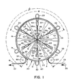
- a rotatable drum 20 having a drum wall 21 with an outer cylindrical surface 22 is driven in the direction indicated by arrow 23 by drive means (Figure 2) comprised of drive motor 10 coupled to drive shaft 41 to rotate it and thereby rotatable drum 20.
- a continuous travelling web 24 of material to be ultrasonically bonded is introduced to the apparatus in the direction shown by arrow 25 for passage onto a rotating feed roll 26 mounted on a shaft 27, from which the web 24 is introduced onto the outer cylindrical surface 22 of the rotatable drum 20 at a first position A and subsequently is removed from the outer cylindrical surface 22 at a second position B circumferentially spaced from the first position A.
- Cylindrical surface 22 between points A and B thereof in the direction of drum travel defines a travel path for the web 24, the ultrasonically bonded product web 61 being removed from rotatable drum 20 at position B, by means of rotatable take-off roll 57 mounted on shaft 58, and discharged from the apparatus in the direction shown by arrow 62.
- the travel path of the web along drum 20 thus defines an arc subtending on angle beta which may be on the order of from about 90° to about 330°, and more preferably from about 120° to about 300°.
- anvils 28, 29, 30, 31, 32 and 33 Disposed outwardly of and equally spaced-apart along the periphery of the drum 20 are anvils 28, 29, 30, 31, 32 and 33. Disposed inwardly of and equally spaced-apart along the periphery of the drum 20 are sonotrodes 42, 43, 44, 45, 46 and 47, respective ones of which are aligned with the respective ones of the anvils along radii of the drum 20, each paired anvil and sonotrode comprising a component of an ultrasonic bonder. Each of the sonotrodes 42-47 has at its outer extremity a bonding surface 59 and each of the anvils 28-33 has at its outer extremity a bonding surface 60.
- a wall opening 54 ( Figure 3) in the wall 21 of drum 20. (Only one such opening is shown in Figure 3, for clarity of illustration.)
- Each of the sonotrodes is mounted for reciprocating movement, respectively, on mounting shafts 48, 49, 50, 51, 52 and 53.
- each of the shafts is fixed by suitable means (not shown) to the drive shaft 41, such as by being received within a hub collar 65 ( Figure 3) of a radial arm support comprised of hub collar 65, which is fixedly mounted upon shaft 41 for rotation therewith and two sets of radially extending arms 67 ( Figures 1 and 3) at each end of hub collar 65.
- the radial arm support mounts rotatable drum 20 upon shaft 41 for rotation therewith.
- Drive shaft 41 is thus driven by the drive motor 10 ( Figure 2) for rotation of the rotatable drum 20 and the sonotrodes 42-47 in synchrony therewith.
- Reciprocating movement of sonotrodes 42-47 or their respective mounting shafts 48-53 may be attained by any suitable means, such as by use of cam followers and slidably mounted or telescoping support shafts, the cam followers engaging eccentric cam tracks to impart a non-circular orbiting path to the sonotrodes so that they reciprocate radially during each orbit.
- Another expedient, illustrated in the drawings, is to mount the sonotrodes 42-47 for sliding movement along their respective shafts 48-53 and to provide a worm gear drive driven by a small electric motor to slide the sonotrode along its respective mounting shaft and thereby radially reciprocate the sonotrode relative to the drum outer surface 22.
- Such motorized worm gear drives are schematically shown as drives 48a, 49a, 50a, 51a, 52a and 53a mounted, respectively, on the correspondingly numbered shafts.
- a switch plate 34 ( Figures 1 and 3) is provided in the form of an arcuate stationary plate mounted adjacent to rotatable drum 20 and defining an arc subtending an angle alpha ( Figure 1) which may be on the order of from about 30° to about 200°, and more preferably is from about 45° to about 180°.
- Each of the mounting shafts 48, 49, 50, 51, 52 and 53 is provided with a respective sensing switch 35, 36, 37, 38, 39 and 40, mounted thereon.
- the sensing switches may comprise electric eye devices or other electrical or electronic devices which sense the location of switch plate 34 or indicia or apertures or other trigger means thereon.
- the bonding surface of the sonotrode is presented via wall openings 54 in drum 20 ( Figures 1 and 3) at the outer cylindrical surface 22 thereof as shown for sonotrodes 42, 43 and 44 in Figure 1.
- the end thereof is sensed by the associated one of switches 35-40 and the switch activates its associated worm gear drive to radially retract the associated sonotrode for the balance of its orbital path.
- Periodic radial translation of the sonotrode along its associated shaft is thus carried out by the worm gears during each revolution of drum 20.
- the anvils 28, 29, 30, 31 and 33 are mounted upon a spider carousel 70 (Figure 2) comprising a plurality of carrier rods, of which rods 72, 73, 74, 75 and 76 are visible in Figure 2.
- Each carrier rod is joined to a respective one of spokes 72a-76a which is received within a hub 81 which is coupled via a drive shaft 82 to a carousel drive motor 83, whereby the spider carousel 70 may be rotated for orbiting of the anvils exteriorly of drum 20, about the periphery thereof.
- Drive motors 83 and 10 are synchronized so that sonotrodes 42-47 and anvils 28-33 orbit in unison, i.e., synchronously, with each other and with rotation of drum 20.
- both the drum 20 and the spider carousel 70 could be driven by a single motor.
- the drive motor 83 joined to shaft 82 could, by extension of the shaft 82, be connected to rotatable drum 20 to drive it in place of drive shaft 41 and drive motor 10.
- cam block 68 Positioned adjacent the rotatable drum 20 is a stationary cam block 68 ( Figures 2 and 3) having a cylindrical shape and outer surface roughly comparable to outer surface 22 of drum 20.
- Cam block 68 is provided on its outer cylindrical surface with a cam track 69 having helical turns in it, visible in Figure 2 at the opposite ends of cam block 68.
- Each of the anvils 28, 29, 30, 31, 32 and 33 are mounted on respective ones of a series of mounting blocks. Only mounting blocks 28a, 30a, 31a and 33a associated with, respectively, anvils 28, 30, 31 and 33 are visible in Figure 2 and only mounting block 29a associated with anvil 29 is shown in Figure 3.
- Each of the mount ing blocks is mounted for sliding reciprocating movement on an associated carrier rod 72-76 and has thereon a cam follower, a typical one of which, cam follower 29b, is visible in Figure 3 and is the only cam follower shown in the drawings.
- cam follower is engaged with cam track 69 of cam block 68, described below.
- the respective mounting blocks are suitably provided with internal mounting means including stop means to provide for low friction reciprocal sliding movement of the mounting blocks between set limits along the associated carrier rods 72-76.
- the anvils reciprocate on the carrier rods because the cam followers (e.g., cam follower 29b, Figure 3) are constrained to follow the path of cam track 69.
- the sonotrodes 42-47 are positioned interiorly of the rotatable drum and are radially outwardly extended to present their respective bonding surface 59 at the outer cylindrical surface 22 of the drum via an opening 54 during orbiting of the sonotrodes along the bonding zone segment (subtended by the angle alpha) of its travel path.
- the cooperating anvils 28-33 are positioned to orbit exteriorly of the rotatable drum 20 whereby during the bonding zone portion of the travel path about the periphery of rotatable drum 20, successive sonotrode bonding surfaces 59 are brought into facing alignment with the corresponding anvil bonding surfaces 60 to clamp the travelling web material 24 therebetween.
- actuator means When the respective bonding surfaces of an anvil and corresponding sonotrode are brought into such facing alignment with one another on either side of the web 24, actuator means energize the sonotrode to emit ultrasonic vibrations for ultrasonic bonding of the web.
- the actuator means may suitably comprise the aforementioned switches 35-40, which can serve not only to actuate extension and retraction of the sonotrodes, but energization thereof.
- the sonotrode bonding surfaces 59 are brought into engaged position within the bonding zone the sonotrodes are energized.
- the bonding surfaces of those anvils (28, 29 and 30) within the bonding zone are in contacting relationship with the outer surface of the web 24 to be bonded.
- those anvils (31 and 33) outside of the bonding zone are in axially spaced relationship to the surface of the rotatable drum and therefore to the web 24, as shown in Figure 2, in which the orbital path travel including axial translation of the anvil means 28-33 about and exteriorly of rotatable drum 20 is clearly shown.
- "Axial” as used herein and in the claims refers to a direction along the axis of rotation and orbiting, i.e., the longitudinal axis of shafts 41 and 82. All reference to a planar projection of a travel path herein and in the claims, refers to projection onto a plane which is perpendicular to the axis of rotation/orbiting.
- FIG. 3 is simplified for clarity, showing only the uppermost positioned anvil 29 and, in dotted outline, sonotrode 43, the latter being disposed interiorly of drum 20. Only a cross section of web 24 at the top (as viewed in the drawing) is shown, the remainder of web 24 being omitted for clarity of illustration.
- Anvil 29 is carried by a mounting block 29a which carries the cam follower 29b extending downwardly (as viewed in the drawing) therefrom and, as described above, engaging recessed cam track 69 of the cam block 68.
- mounting block 29a is mounted for reciprocating movement on carrier rod 74, whereby the anvil 29 will be axially translated by reciprocating movement imposed upon it by virtue of cam follower 29b following cam track 69.
- the bonding surfaces 60 ( Figure 1) of the anvils are aligned with openings 54 in drum 20 and bonding surfaces 59 of radially extended sonotrodes 42-44.
- cam track 69 curves away from drum 20 and follows a path (dotted line portion in Figure 2) which is axially further from drum 20 than the bonding zone segment of cam track 69, whereby anvils 28-33 are axially translated away from drum 20 by sliding movement along their associated carrier rods 72-76.
- anvil 31 is moving away from drum 20 so that it will clear the bonded portion 61 of the web being withdrawn from drum 20.
- Anvil 33 is moving towards drum 20 to get into alignment therewith prior to or at the point of entering the bonding zone segment of the travel path of web 24, but its axially displaced location in Figure 2 allows room for entry of web 24 onto drum 20.
- anvils 28-33 when they are in their bonding zone position they are radially positioned to be in engagement with the outer surface of the web 24 and sonotrodes 42-47 are radially extended to be in engagement with the inner (drum-side) surface of web 24, so that the web is clamped therebetween to effect bonding while the sonotrode 43 is energized.
- the array of anvils is orbited synchronously with the rotation of the rotatable drum and the orbiting of the array of sonotrodes disposed therein.
- the sonotrodes are preferably radially extended to effect bonding during the passage of the web along the bonding zone segment of the travel path and radially withdrawn to a retracted position when the portion of the drum associated therewith is outside the bonding zone segment of the travel path.
- the radial retraction saves wear on the sonotrode bonding surfaces but the invention could be operated with the sonotrode bonding surfaces permanently mounted in the radially extended position.
- the planar projection as defined above, i.e., onto a plane perpendicular to the axis of rotation of the closed orbital travel path of sonotrodes 42-47 (and their bonding surfaces) is oval in the illustrated embodiment, but it could be circular.
- the planar projection of the closed orbital travel path of anvils 28-33 is circular and, in the illustrated embodiment, is an outer closed travel path which encircles at least the bonding zone segment of the inner closed travel path defined by the sonotrodes.
- the inner and outer closed travel paths, or at least their projection onto the plane are concentric, but they need not necessarily be. For example, if the inner closed circular path is oval it need not be concentric with the outer closed travel path.
- the anvils are disposed outwardly on and equally spaced apart along the periphery of the drum.
- sonotrodes Positionally outwardly of and equally spaced-apart along the periphery of the drum are sonotrodes.
- Each sonotrode is mounted for reciprocating movement, on mounting shafts and levers.
- the levers are slideably mounted on their respective mounting shaft and moved to and away from the anvil area during each orbit of the drum.
- the reciprocating movement of the sonotrodes and their levers may be attained by any suitable means such as by use of cam followers engaging eccentric cam tracks to impart a nonplanar orbiting path to the sonotrodes so that they reciprocate axially during each orbit.
- the sonotrodes are brought into contact with the anvil by rotating the lever to move the sonotrodes radially inward and outward for a preselected portion of the nonplanar orbit described above.
- the period of contact between the sonotrode and anvil is defined broadly by the dimensions of the drum and the rate of rotation. However, more importantly, within the more narrow operating region, the lever may be controlled to maintain contact between the anvil and sonotrodes for a desired period of time irrespective of the rate of rotation or diameter of the drum.
- the ultrasonic bonding carried out by the invention may also include cutting.
- cutting for example, as disclosed in commonly owned copending patent application Serial No. 800,017 of J.J. Samida and J.I. Van Deurzen entitled, "Apparatus and Method For Contemporaneously Bonding and Severing An Ultrasonically Fusible Material” (Attorney Docket 7105), the entire disclosure of which is incorporated by reference herein, ultrasonic bonders which sever as well as bond may be utilized as the ultrasonic bonders used in the invention. Whether using such ultrasonic bonding/severing means or not, the continuous web illustrated in describing the illustrated embodiment of the invention may be cut into discrete articles as part of the process, or it may be discharged from the process as a continuous web.
Landscapes
- Engineering & Computer Science (AREA)
- Mechanical Engineering (AREA)
- Pressure Welding/Diffusion-Bonding (AREA)
- Lining Or Joining Of Plastics Or The Like (AREA)
Applications Claiming Priority (2)
| Application Number | Priority Date | Filing Date | Title |
|---|---|---|---|
| US06/878,143 US4758293A (en) | 1986-06-25 | 1986-06-25 | Ultrasonic bonding apparatus and method |
| US878143 | 1997-06-18 |
Publications (2)
| Publication Number | Publication Date |
|---|---|
| EP0251070A2 true EP0251070A2 (fr) | 1988-01-07 |
| EP0251070A3 EP0251070A3 (fr) | 1990-06-27 |
Family
ID=25371468
Family Applications (1)
| Application Number | Title | Priority Date | Filing Date |
|---|---|---|---|
| EP87108808A Withdrawn EP0251070A3 (fr) | 1986-06-25 | 1987-06-19 | Procédé et appareil de soudage par ultra-sons |
Country Status (4)
| Country | Link |
|---|---|
| US (1) | US4758293A (fr) |
| EP (1) | EP0251070A3 (fr) |
| AU (1) | AU588115B2 (fr) |
| CA (1) | CA1306933C (fr) |
Cited By (8)
| Publication number | Priority date | Publication date | Assignee | Title |
|---|---|---|---|---|
| WO1996023645A1 (fr) * | 1995-01-31 | 1996-08-08 | Kimberly-Clark Worldwide, Inc. | Appareil de soudage rotatif |
| US5753343A (en) * | 1992-08-04 | 1998-05-19 | Minnesota Mining And Manufacturing Company | Corrugated nonwoven webs of polymeric microfiber |
| AU715601B2 (en) * | 1995-01-31 | 2000-02-03 | Kimberly-Clark Worldwide, Inc. | Rotary sealing system |
| WO2005007513A1 (fr) * | 2003-07-21 | 2005-01-27 | I.M.A. Industria Macchine Automatiche S.P.A. | Dispositif servant a sceller des bandes de papier filtre |
| EP1868182A1 (fr) * | 2006-06-14 | 2007-12-19 | Telsonic Holding AG | Générateur d'ultrasons avec liquide de refroidissement, système de soudure, et procédé d'opération d'un générateur d'ultrasons |
| CN105710524A (zh) * | 2016-01-22 | 2016-06-29 | 安庆市恒昌机械制造有限责任公司 | 一种用于材料加工的超声波处理装置及方法 |
| CN106079419A (zh) * | 2016-07-29 | 2016-11-09 | 安庆市恒昌机械制造有限责任公司 | 一种用于材料加工的压合处理装置及方法 |
| CN119630306A (zh) * | 2022-05-24 | 2025-03-14 | 金伯利-克拉克环球有限公司 | 用于接缝粘合机的突出部定位器 |
Families Citing this family (62)
| Publication number | Priority date | Publication date | Assignee | Title |
|---|---|---|---|---|
| US5057182A (en) * | 1990-01-19 | 1991-10-15 | Sonokinetics Group | Ultrasonic comb horn and methods for using same |
| US5171387A (en) * | 1990-01-19 | 1992-12-15 | Sonokinetics Group | Ultrasonic comb horn and methods for using same |
| US5094657A (en) * | 1990-11-29 | 1992-03-10 | Cloud Corporation | Method and apparatus for continuously forming and sealing low density polyethylene bags at high speed |
| US5215514A (en) * | 1991-09-06 | 1993-06-01 | Fas Converting Machinery Ab | Method and arrangement in a bag-making machine for forming weld lines in a web fed therethrough |
| US5723223A (en) * | 1991-10-07 | 1998-03-03 | International Paper Company | Ultrasonically bonded microwave susceptor material and method for its manufacture |
| DE4325877B4 (de) * | 1993-08-02 | 2004-01-29 | Windmöller & Hölscher Kg | Vorrichtung zum Verschweißen der Schlauchabschnitte von Säcken, Beuteln oder dergleichen |
| CA2129496A1 (fr) | 1994-04-12 | 1995-10-13 | Mary Lou Delucia | Voiles a base de fibres conjuguees en polymere simple de resistance, amelioree |
| TW253870B (en) | 1994-07-11 | 1995-08-11 | Newell Operating Co | Cellular panel and method and apparatus for making the same |
| DE4434132A1 (de) * | 1994-09-24 | 1996-03-28 | Bosch Gmbh Robert | Ultraschall-Schweißverfahren und Ultraschall-Schweißvorrichtung sowie eine damit hergestellte Schweißverbindung |
| US5733411A (en) * | 1995-12-21 | 1998-03-31 | Kimberly-Clark Corporation | Ultrasonic system |
| WO1997027996A1 (fr) * | 1996-02-02 | 1997-08-07 | Fmc Corporation | Machine a fabriquer des sacs a soudage par blanchet |
| US5817199A (en) * | 1996-12-20 | 1998-10-06 | Kimberly-Clark Worldwide, Inc. | Methods and apparatus for a full width ultrasonic bonding device |
| DE19753740C1 (de) * | 1997-12-04 | 1999-07-15 | Herrmann Ultraschalltechnik | Vorrichtung zum Bearbeiten einer Materialbahn |
| US6123792A (en) * | 1998-08-14 | 2000-09-26 | Kimberly-Clark Worldwide, Inc. | Methods and apparatus for intermittent rotary ultrasonic bonding system |
| US6524251B2 (en) | 1999-10-05 | 2003-02-25 | Omnisonics Medical Technologies, Inc. | Ultrasonic device for tissue ablation and sheath for use therewith |
| US6551337B1 (en) | 1999-10-05 | 2003-04-22 | Omnisonics Medical Technologies, Inc. | Ultrasonic medical device operating in a transverse mode |
| US20040097996A1 (en) | 1999-10-05 | 2004-05-20 | Omnisonics Medical Technologies, Inc. | Apparatus and method of removing occlusions using an ultrasonic medical device operating in a transverse mode |
| JP3410423B2 (ja) | 2000-03-21 | 2003-05-26 | 東亜機工株式会社 | 溶着重合体の製造方法及びその装置 |
| CA2439810C (fr) * | 2001-03-28 | 2006-10-31 | Akihide Ninomiya | Appareil d'etancheite et procede de fabrication d'articles mous comportant une partie etanche |
| US6574944B2 (en) * | 2001-06-19 | 2003-06-10 | Mars Incorporated | Method and system for ultrasonic sealing of food product packaging |
| US6730188B2 (en) | 2001-09-14 | 2004-05-04 | Kimberly-Clark Worldwide, Inc. | Method and apparatus for assembling refastenable absorbent garments |
| US6743321B2 (en) * | 2001-09-14 | 2004-06-01 | Kimberly-Clark Worldwide, Inc. | Method and apparatus for assembling refastenable absorbent garments |
| US6682626B2 (en) | 2001-09-14 | 2004-01-27 | Kimberly-Clark Worldwide, Inc. | Method and apparatus for assembling refastenable absorbent garments |
| US6820671B2 (en) * | 2001-10-05 | 2004-11-23 | Paragon Trade Brands, Inc. | Apparatus and method for assembling absorbent garments |
| US6612479B2 (en) * | 2001-10-10 | 2003-09-02 | Ford Global Technologies, Llc | Apparatus and method for joining layers of materials |
| US6620270B2 (en) | 2001-12-18 | 2003-09-16 | Kimberly-Clark Worldwide, Inc. | Control of processing force and process gap in rigid rotary ultrasonic systems |
| US6613171B2 (en) | 2001-12-18 | 2003-09-02 | Kimberly-Clark Worldwide, Inc. | Rotary ultrasonic bonder or processor capable of fixed gap operation |
| US6537403B1 (en) | 2001-12-18 | 2003-03-25 | Kimberly-Clark Worldwide, Inc. | Nip adjustment for a rigid ultrasonic bonder or processor |
| US6547903B1 (en) | 2001-12-18 | 2003-04-15 | Kimberly-Clark Worldwide, Inc. | Rotary ultrasonic bonder or processor capable of high speed intermittent processing |
| US6676003B2 (en) | 2001-12-18 | 2004-01-13 | Kimberly-Clark Worldwide, Inc. | Rigid isolation of rotary ultrasonic horn |
| AU2003245780B2 (en) * | 2002-08-20 | 2010-04-22 | Ferag Ag | Device for processing flat objects, especially for packing printed products |
| JP4297715B2 (ja) * | 2003-03-31 | 2009-07-15 | ユニ・チャーム株式会社 | シール装置および前記シール装置を用いたシール方法 |
| US7108759B2 (en) | 2003-12-19 | 2006-09-19 | Kimberly-Clark Worldwide, Inc. | Method for improved bond strength in an elastomeric material |
| US7794414B2 (en) | 2004-02-09 | 2010-09-14 | Emigrant Bank, N.A. | Apparatus and method for an ultrasonic medical device operating in torsional and transverse modes |
| US20070259765A1 (en) * | 2006-05-08 | 2007-11-08 | Chun-Shan Chen | Plastic bag sealing device |
| US7503156B2 (en) * | 2007-01-11 | 2009-03-17 | Ralph Eibert | Method and apparatus for making dunnage |
| ITMI20080392A1 (it) * | 2008-03-10 | 2009-09-11 | Sitma Spa | Gruppo confezionatore ad alta velocita' e macchina confezionatrice dotata di tale gruppo |
| US8100253B2 (en) | 2009-06-30 | 2012-01-24 | The Procter & Gamble Company | Methods and apparatuses for transferring discrete articles between carriers |
| JP5575500B2 (ja) * | 2010-02-10 | 2014-08-20 | ユニ・チャーム株式会社 | 使い捨て着用物品を含む物品群 |
| JP5591051B2 (ja) * | 2010-09-30 | 2014-09-17 | ユニ・チャーム株式会社 | ウエブに超音波処理を施すための装置および方法 |
| JP5851297B2 (ja) * | 2012-03-22 | 2016-02-03 | ユニ・チャーム株式会社 | ウエブに超音波処理を施すための装置および方法 |
| US8820513B2 (en) | 2012-04-16 | 2014-09-02 | The Procter & Gamble Company | Methods for transferring discrete articles |
| US8607959B2 (en) | 2012-04-16 | 2013-12-17 | The Procter & Gamble Company | Rotational assemblies and methods for transferring discrete articles |
| US8833542B2 (en) | 2012-04-16 | 2014-09-16 | The Procter & Gamble Company | Fluid systems and methods for transferring discrete articles |
| US8720666B2 (en) | 2012-04-16 | 2014-05-13 | The Procter & Gamble Company | Apparatuses for transferring discrete articles |
| EP2911628B1 (fr) | 2012-10-23 | 2019-05-15 | The Procter and Gamble Company | Composants de support ou surfaces de transfert ayant un composant résilient |
| JP2014097097A (ja) * | 2012-11-13 | 2014-05-29 | Zuiko Corp | ウエブの溶着システムおよび溶着方法 |
| US9956738B1 (en) * | 2013-03-08 | 2018-05-01 | Paul A. Olson | Automated bag former |
| WO2014200104A1 (fr) * | 2013-06-14 | 2014-12-18 | 株式会社瑞光 | Dispositif de soudage ultrasonique et procédé de production de couche jetable utilisant celui-ci |
| US9463942B2 (en) | 2013-09-24 | 2016-10-11 | The Procter & Gamble Company | Apparatus for positioning an advancing web |
| JP6228233B2 (ja) * | 2013-12-26 | 2017-11-08 | 株式会社瑞光 | 超音波溶着装置 |
| KR101836754B1 (ko) * | 2013-12-26 | 2018-03-08 | 가부시키가이샤 즈이코 | 초음파 용착 장치 |
| US10259165B2 (en) | 2015-04-01 | 2019-04-16 | Aurizon Ultrasonics, LLC | Apparatus for fabricating an elastic nonwoven material |
| US9511951B1 (en) | 2015-06-23 | 2016-12-06 | The Procter & Gamble Company | Methods for transferring discrete articles |
| US9511952B1 (en) | 2015-06-23 | 2016-12-06 | The Procter & Gamble Company | Methods for transferring discrete articles |
| EP3904057B1 (fr) | 2016-09-30 | 2023-05-24 | Dukane IAS, LLC | Appareil et procédé de fabrication d'un matériau non-tissé élastique |
| IT201700008422A1 (it) * | 2017-01-26 | 2017-04-26 | Fameccanica Data Spa | Apparecchio per la saldatura trasversale di un nastro in movimento |
| US10913211B2 (en) | 2017-05-30 | 2021-02-09 | Campbell Soup Company | High rate ultrasonic sealer |
| KR102842379B1 (ko) | 2019-03-22 | 2025-08-06 | 듀케인 아이에이에스, 엘엘씨 | 탄성 부직포 재료를 제조하기 위한 장치 |
| CN111248565A (zh) * | 2020-03-30 | 2020-06-09 | 广州市兴世机械制造有限公司 | 穿着物生产系统、封合装置及输送机构 |
| IT202000016210A1 (it) * | 2020-07-06 | 2022-01-06 | Gdm Spa | Dispositivo rotativo di saldatura e relativo metodo |
| US11919253B2 (en) * | 2022-07-21 | 2024-03-05 | Rohr, Inc. | Welding assembly and method using separately actuatable rams |
Family Cites Families (20)
| Publication number | Priority date | Publication date | Assignee | Title |
|---|---|---|---|---|
| US2732887A (en) * | 1956-01-31 | Heat-sealing of thermoplastic | ||
| FR978204A (fr) * | 1948-12-24 | 1951-04-11 | Presse multiple, rotative, pour découpage, emboutissage, cambrage | |
| FR1536420A (fr) * | 1967-06-29 | 1968-08-16 | Eastman Kodak Co | Nouvel appareil d'emballage en continu |
| DE1632007A1 (de) * | 1967-08-03 | 1970-08-20 | Stunck & Co Maschinenfabrik M | Vorrichtung zum Verschliessen von Hohlkoerpern,vorzugsweise Flaschen aus thermoplastischem Kunststoff durch Verschweissen mittels Ultraschall |
| US3509799A (en) * | 1967-08-04 | 1970-05-05 | Crown Zellerbach Corp | Bag-forming method |
| US3837977A (en) * | 1972-09-15 | 1974-09-24 | Crompton & Knowles Corp | Ultrasonic pattern welding apparatus |
| US3844869A (en) * | 1972-12-20 | 1974-10-29 | Crompton & Knowles Corp | Apparatus for ultrasonic welding of sheet materials |
| US3996724A (en) * | 1975-10-16 | 1976-12-14 | Ex-Cell-O Corporation | Rotary carton closing and sealing apparatus |
| ZA77281B (en) * | 1976-01-28 | 1977-11-30 | Ex Cell O Corp | Apparatus and method for vibration sealing |
| US4047992A (en) * | 1976-03-02 | 1977-09-13 | Eastman Kodak Company | Turn-on method and apparatus for ultrasonic operations |
| US4193833A (en) * | 1978-04-24 | 1980-03-18 | Ex-Cell-O Corporation | Ultrasonic packaging machine |
| SU785051A1 (ru) * | 1978-06-05 | 1980-12-07 | Омский политехнический институт | Устройство дл шовной ультразвуковой сварки полимерных материалов |
| US4305240A (en) * | 1979-07-05 | 1981-12-15 | Domain Industries | Package forming and sealing apparatus |
| NL7906324A (nl) * | 1979-08-21 | 1981-02-24 | Meulen Leonard V D | Vervaardiging van draagtassen. |
| US4414045A (en) * | 1982-02-22 | 1983-11-08 | Burlington Industries, Inc. | High speed ultrasonic bonding |
| US4490199A (en) * | 1982-07-01 | 1984-12-25 | Allied Corporation | Method and apparatus for splicing polymeric webs |
| US4534818A (en) * | 1983-12-22 | 1985-08-13 | Frito-Lay, Inc. | Method and apparatus for ultrasonic sealing |
| GB2162460B (en) * | 1984-07-31 | 1987-07-22 | Shibuya Kogyo Co Ltd | Apparatus for transversely sealing packages |
| US4650530A (en) * | 1986-03-10 | 1987-03-17 | Kimberly-Clark Corporation | Apparatus and method for folding, bonding and severing a web |
| US4713132A (en) * | 1986-05-08 | 1987-12-15 | Kimberly-Clark Corporation | Apparatus and method for ultrasonic bonding of a moving web |
-
1986
- 1986-06-25 US US06/878,143 patent/US4758293A/en not_active Expired - Lifetime
-
1987
- 1987-05-27 CA CA000538091A patent/CA1306933C/fr not_active Expired - Lifetime
- 1987-06-19 EP EP87108808A patent/EP0251070A3/fr not_active Withdrawn
- 1987-06-22 AU AU74556/87A patent/AU588115B2/en not_active Ceased
Cited By (13)
| Publication number | Priority date | Publication date | Assignee | Title |
|---|---|---|---|---|
| US5753343A (en) * | 1992-08-04 | 1998-05-19 | Minnesota Mining And Manufacturing Company | Corrugated nonwoven webs of polymeric microfiber |
| US5763078A (en) * | 1992-08-04 | 1998-06-09 | Minnesota Mining And Manufacturing Company | Filter having corrugated nonwoven webs of polymeric microfiber |
| WO1996023645A1 (fr) * | 1995-01-31 | 1996-08-08 | Kimberly-Clark Worldwide, Inc. | Appareil de soudage rotatif |
| US5660679A (en) * | 1995-01-31 | 1997-08-26 | Kimberly-Clark Worldwide, Inc. | Rotary sealing system |
| AU706086B2 (en) * | 1995-01-31 | 1999-06-10 | Kimberly-Clark Worldwide, Inc. | Rotary sealing system |
| AU715601B2 (en) * | 1995-01-31 | 2000-02-03 | Kimberly-Clark Worldwide, Inc. | Rotary sealing system |
| WO2005007513A1 (fr) * | 2003-07-21 | 2005-01-27 | I.M.A. Industria Macchine Automatiche S.P.A. | Dispositif servant a sceller des bandes de papier filtre |
| US7299600B2 (en) | 2003-07-21 | 2007-11-27 | I.M.A. Industria Macchine Automatiche S.P.A. | Device for sealing lengths of filter paper |
| EP1868182A1 (fr) * | 2006-06-14 | 2007-12-19 | Telsonic Holding AG | Générateur d'ultrasons avec liquide de refroidissement, système de soudure, et procédé d'opération d'un générateur d'ultrasons |
| CN105710524A (zh) * | 2016-01-22 | 2016-06-29 | 安庆市恒昌机械制造有限责任公司 | 一种用于材料加工的超声波处理装置及方法 |
| CN105710524B (zh) * | 2016-01-22 | 2018-05-04 | 安庆市恒昌机械制造有限责任公司 | 一种用于材料加工的超声波处理装置及方法 |
| CN106079419A (zh) * | 2016-07-29 | 2016-11-09 | 安庆市恒昌机械制造有限责任公司 | 一种用于材料加工的压合处理装置及方法 |
| CN119630306A (zh) * | 2022-05-24 | 2025-03-14 | 金伯利-克拉克环球有限公司 | 用于接缝粘合机的突出部定位器 |
Also Published As
| Publication number | Publication date |
|---|---|
| CA1306933C (fr) | 1992-09-01 |
| AU7455687A (en) | 1988-01-07 |
| US4758293A (en) | 1988-07-19 |
| AU588115B2 (en) | 1989-09-07 |
| EP0251070A3 (fr) | 1990-06-27 |
Similar Documents
| Publication | Publication Date | Title |
|---|---|---|
| US4758293A (en) | Ultrasonic bonding apparatus and method | |
| EP0807013B1 (fr) | Appareil de soudage rotatif | |
| US4650530A (en) | Apparatus and method for folding, bonding and severing a web | |
| US4713132A (en) | Apparatus and method for ultrasonic bonding of a moving web | |
| US5518566A (en) | Method and apparatus for combining a tensioned elastic garter | |
| CA1094936A (fr) | Methode et appareil de fixation d'une bande transversalement a une trame mobile | |
| US6165298A (en) | Patterned anvil-roll | |
| EP1302424B1 (fr) | Modulateur de la vitesse d'une bande | |
| US4968369A (en) | Belt fabrication machine | |
| US6287403B1 (en) | Support system for rotary function rolls | |
| US4490199A (en) | Method and apparatus for splicing polymeric webs | |
| EP2094470B1 (fr) | Soudure ultra-sons rotative | |
| JPH01114420A (ja) | 熱可塑性フイルムから袋を連続的に製造する方法およびその装置 | |
| JPH0567496B2 (fr) | ||
| JPH0653360B2 (ja) | シート材を接合切断する超音波装置 | |
| US6368437B1 (en) | Rotary bonding apparatus and method | |
| US9821511B2 (en) | Ultrasonic welding device with preheating unit | |
| JPS6097838A (ja) | プラスチツク製手提袋を製造するための方法 | |
| WO2008091599A1 (fr) | Brosses fibreuses angulaires constituées de fibres fixées à un support et leur procédé de fabrication | |
| JPS6130965B2 (fr) | ||
| JP2019507690A (ja) | 超音波シーラー | |
| EP1108510B1 (fr) | Procede et dispositif de production pour matiere plastique assemblee | |
| JP2001260237A (ja) | 溶着重合体の製造方法及びその装置 | |
| CA2247695C (fr) | Procede at appreil permettant de combiner un collier elastique tendu avec un substrat | |
| JPH088079Y2 (ja) | 超音波加工機 |
Legal Events
| Date | Code | Title | Description |
|---|---|---|---|
| PUAI | Public reference made under article 153(3) epc to a published international application that has entered the european phase |
Free format text: ORIGINAL CODE: 0009012 |
|
| AK | Designated contracting states |
Kind code of ref document: A2 Designated state(s): AT BE CH DE ES FR GB GR IT LI LU NL SE |
|
| PUAL | Search report despatched |
Free format text: ORIGINAL CODE: 0009013 |
|
| AK | Designated contracting states |
Kind code of ref document: A3 Designated state(s): AT BE CH DE ES FR GB GR IT LI LU NL SE |
|
| 17P | Request for examination filed |
Effective date: 19901227 |
|
| STAA | Information on the status of an ep patent application or granted ep patent |
Free format text: STATUS: THE APPLICATION IS DEEMED TO BE WITHDRAWN |
|
| 18D | Application deemed to be withdrawn |
Effective date: 19920102 |
|
| RIN1 | Information on inventor provided before grant (corrected) |
Inventor name: SAMIDA, JEFFREY JOSEPH |