EP0251535A2 - Systèmes d'actionnement redondants en parallèle - Google Patents
Systèmes d'actionnement redondants en parallèle Download PDFInfo
- Publication number
- EP0251535A2 EP0251535A2 EP87305203A EP87305203A EP0251535A2 EP 0251535 A2 EP0251535 A2 EP 0251535A2 EP 87305203 A EP87305203 A EP 87305203A EP 87305203 A EP87305203 A EP 87305203A EP 0251535 A2 EP0251535 A2 EP 0251535A2
- Authority
- EP
- European Patent Office
- Prior art keywords
- lane
- input
- torque
- output
- lanes
- Prior art date
- Legal status (The legal status is an assumption and is not a legal conclusion. Google has not performed a legal analysis and makes no representation as to the accuracy of the status listed.)
- Withdrawn
Links
- 239000012530 fluid Substances 0.000 claims description 6
- 230000007423 decrease Effects 0.000 claims description 3
- 238000004804 winding Methods 0.000 description 13
- 230000000712 assembly Effects 0.000 description 4
- 238000000429 assembly Methods 0.000 description 4
- 230000004907 flux Effects 0.000 description 2
- RZVHIXYEVGDQDX-UHFFFAOYSA-N 9,10-anthraquinone Chemical compound C1=CC=C2C(=O)C3=CC=CC=C3C(=O)C2=C1 RZVHIXYEVGDQDX-UHFFFAOYSA-N 0.000 description 1
- 230000005355 Hall effect Effects 0.000 description 1
- 238000007596 consolidation process Methods 0.000 description 1
- 230000001419 dependent effect Effects 0.000 description 1
- 238000010586 diagram Methods 0.000 description 1
- 230000003467 diminishing effect Effects 0.000 description 1
- 238000006073 displacement reaction Methods 0.000 description 1
- 230000000694 effects Effects 0.000 description 1
- 238000005259 measurement Methods 0.000 description 1
Images

Classifications
-
- G—PHYSICS
- G05—CONTROLLING; REGULATING
- G05D—SYSTEMS FOR CONTROLLING OR REGULATING NON-ELECTRIC VARIABLES
- G05D3/00—Control of position or direction
- G05D3/12—Control of position or direction using feedback
- G05D3/14—Control of position or direction using feedback using an analogue comparing device
-
- G—PHYSICS
- G05—CONTROLLING; REGULATING
- G05D—SYSTEMS FOR CONTROLLING OR REGULATING NON-ELECTRIC VARIABLES
- G05D1/00—Control of position, course, altitude or attitude of land, water, air or space vehicles, e.g. using automatic pilots
- G05D1/0055—Control of position, course, altitude or attitude of land, water, air or space vehicles, e.g. using automatic pilots with safety arrangements
- G05D1/0077—Control of position, course, altitude or attitude of land, water, air or space vehicles, e.g. using automatic pilots with safety arrangements using redundant signals or controls
Definitions
- This invention relates to parallel redundant actuator systems.
- a parallel redundant actuator system a plurality of demand signals each indicating the desired position of an output member of the system are respectively applied to a plurality of nominally identical signal lanes whose outputs together control the position of the output member.
- a signal representing the actual position of the output member is fed back to the input end of each lane where it is compared with a lane demand signal, and the error signal is fed via the lane to a summing arrangement to produce an output representative of the sum of the lane output signals which is utilised to control the position of the actuator system output member.
- the summing arrangement comprises a torque motor having a plurality of control windings to which the lane output signals are respectively applied and the motor operates a valve which controls the supply and discharge of pressurised hydraulic fluid to and from a hydraulic actuator whose output member constitutes the output member of the system.
- a parallel redundant actuator system of the kind comprising: a plurality of signal lanes each responsive to the difference between a respective demand signal representing a desired position of an output member of the system and a feedback signal representing the actual position of said output member; a summing arrangement responsive to the outputs of said signal lanes to produce an output signal representative of the sum of the outputs of said lanes; and an actuator responsive to the output of said summing arrangement to control the position of said output member; between the input of each said lane and the output of the summing arrangement the system exhibits a non-linear input/output characteristic whose slope over a range of values of input in which changes of input due to failure of another lane occur is greater than if the characteristic were linear over the range of values of input over which the lane is capable of operation.
- said input/output characteristic has a slope which decreases with increase of input.
- each lane includes a further feedback loop inside the output member position feedback loop
- said input/output characteristic is preferably conferred by a component within the further feedback loop.
- Said input/output characteristic is suitably conferred by the summing arrangement.
- the summing arrangement is suitably constituted by a torque motor.
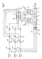
- the system includes a hydraulic ram actuator 1 whose output member is in the form of a rod 3.
- the system controls axial movement of the rod 3, the end of the rod being attached to a device (not shown) whose movement is to be controlled by the system, e.g. a flight control surface of an aircraft.
- the rod 3 is mounted for axial movement in a hollow cylindrical enclosure 5 which is divided into two compartments 7 and 9 by an internal wall 11. At spaced positions along the rod there are two pistons 13 and 15, one piston 13 dividing the compartment 7 into ' two chambers 7A and 7B and the other piston 15 dividing the compartment 9 into two chambers 9A and 9B.
- Each of the compartments 7 and 9 is associated with a respective control valve 17 or 19, the two valves being operated in unison by a dc brushless torque motor 21.
- valves 17 and 19 are controlled by the motor 21 so as either to admit pressurised hydraulic fluid from respective supply lines 23 and 25 to the chambers 7A and 9A respectively and to discharge fluid from chambers 7B and 9B respectively to respective return lines 27 and 29, thereby driving the rod 3 to the right as shown in the Figure, or to admit fluid from supply lines 23 and 25 to chambers 7B and 9B and discharge fluid from chambers 7A and 9A to return lines 27 and 29 to drive the rod 3 to the left as shown in the Figure.
- valves 17 and 19 will incorporate bypass valves to prevent seizure due to hydraulic lock in known manner.
- Each signal lane includes a first summing point 35A, B or C wherein a demand signal representing the desired position of the output member 3 of the system is differenced with a signal representing the actual position of the member 3, derived from a respective one of three position detectors 37A, B and C, to produce an error signal.
- the error signal is passed via a first amplifier 39A, B or C to a second summing point 41A, B or C.
- the output signal of the amplifier 39A, B or C is differenced with a signal representing the current in the corresponding control winding 33A, B or C of the motor 21.
- the resulting error signal is then applied to the corresponding winding 33A, B or C via a second amplifier 43A, B or C.
- the second feedback loop thus provided improves dynamic response of the system in accordance with known servo practice but also has the effect that the output of the amplifier 43A, B or C in a lane tends to go hardover if the feedback loop is broken or earthed.
- each lane 31A, B or C supplies to the motor 21 a signal substantially corresponding to one third of the torque required to be supplied by the motor 21 to operate the rod 3 to the position required by the demand signals.
- the relation between the current input signal supplied to each winding 33A, B or C of the motor 21, and the resulting torque at the motor output is arranged to be non-linear. More particularly, this input/output characteristic is arranged to have a slope which decreases with increasing input.
- the required change of torque supplied y the healthy lanes 31B and C is achieved with a smaller change in the output signals of the summing points 35B and C of the healthy lanes 31B and C, and hence with a smaller offset in the position of the rod 3, than would be the case if the above-mentioned input/output characteristics were linear over the required range of torque.
- the torque sum equation of the motor 21 is:- where T is the total output torque of the motor 21 Im is the maximum value of the input current to each lane; In is the input current to lane n ; K is the torque to current gain factor of each lane; and X and Y are constants. X and Y suitably have values of 1.5 and 1.6 respectively.
- the equation (1) is suitably implemented using a non-linear torque motor 21 of the form shown in Figure 2.
- the motor has three pole pieces 45A, 45B and 45C each of which is energised by a respective one of the windings 33A, 33B and 33C (not shown in Figure 2).
- the pole pieces 45A, 45B, 45C define a central space of generally ogival cross-section and centrally within the space there is a rotor assembly 47 comprising a shaft 49 and three permanent magnet assemblies 51A, 51B and 51C respectively connected to the shaft 49 at equal radial distances therefrom by spring elements 53A, 53B and 53C at positions equally spaced around the shaft 49.
- the magnet assemblies 51A, 51B and 51C are deflected to take up positions symmetrical with respect to the pole pieces 45A, 45B, 45C respectively.
- a more comprehensive function which includes a weighting factor based on the torque differential between each lane and the total output torque T is used, as follows:- where T max is the maximum torque capability of each lane; and Tn is the torque provided by lane n.
- T max is the maximum torque capability of each lane; and Tn is the torque provided by lane n.
- X and Y suitably have values of 3 and 1.4 respectively.
- the equation (2) is suitably implemented using a motor 21 of the form illustrated in Figure 3.
- the motor 21 has a control winding/rotor arrangement which has an approximately linear torque output for the current applied to each winding 33A, 33B or 33C.
- Each winding 33A, 33B, 33C is associated with a respective flux measurement device 55A, 55B or 55C, e.g. a Hall effect device.
- the outputs FA, FB and FC of the devices 55A, 55B and 55C are fed to a voting and consolidation circuit 57 which gives an output having a value representative of the total output torque T of the motor 21.
- this value T is then used together with the value of the flux FA, FB or FC for the appropriate lane to compute, in accordance with equation (2) above, the value of the current I to be applied to each of the control windings 33A, 33B and 33C of the motor 21 at the current gain factor K.
- equation (2) A significant advantage of the equation (2) is its ability to reduce the gain of lanes with null failures. It will however be understood that this second function is relatively complex to implement.
- the non-linear characteristic in each lane 31 is conferred by the torque motor 21, this is not necessarily the case.
- the non-linear characteristic in the lanes may be conferred by a component anywhere in the lanes.
- the lanes include more than one feedback loop the non-linear characteristic should be conferred by a component which is within each feedback loop.
- the use of the torque motor or other summing arrangement to confer the required non-linear lane characteristics is generally most convenient, and moreover, the summing arrangement will normally be a component of higher reliability than other components of the lanes.
Landscapes
- Engineering & Computer Science (AREA)
- Physics & Mathematics (AREA)
- General Physics & Mathematics (AREA)
- Automation & Control Theory (AREA)
- Aviation & Aerospace Engineering (AREA)
- Radar, Positioning & Navigation (AREA)
- Remote Sensing (AREA)
- Feedback Control In General (AREA)
- Safety Devices In Control Systems (AREA)
- Control Of Position Or Direction (AREA)
- Servomotors (AREA)
- Fluid-Pressure Circuits (AREA)
Applications Claiming Priority (2)
| Application Number | Priority Date | Filing Date | Title |
|---|---|---|---|
| GB8615145 | 1986-06-20 | ||
| GB868615145A GB8615145D0 (en) | 1986-06-20 | 1986-06-20 | Parallel redundant actuator systems |
Publications (2)
| Publication Number | Publication Date |
|---|---|
| EP0251535A2 true EP0251535A2 (fr) | 1988-01-07 |
| EP0251535A3 EP0251535A3 (fr) | 1989-01-25 |
Family
ID=10599837
Family Applications (1)
| Application Number | Title | Priority Date | Filing Date |
|---|---|---|---|
| EP87305203A Withdrawn EP0251535A3 (fr) | 1986-06-20 | 1987-06-12 | Systèmes d'actionnement redondants en parallèle |
Country Status (7)
| Country | Link |
|---|---|
| US (1) | US4788483A (fr) |
| EP (1) | EP0251535A3 (fr) |
| JP (1) | JPS6323003A (fr) |
| BR (1) | BR8703097A (fr) |
| GB (1) | GB8615145D0 (fr) |
| IN (1) | IN170756B (fr) |
| YU (1) | YU113887A (fr) |
Cited By (1)
| Publication number | Priority date | Publication date | Assignee | Title |
|---|---|---|---|---|
| EP0404223A3 (fr) * | 1989-06-23 | 1992-05-06 | British Aerospace Public Limited Company | Système de contrôle des actionneurs |
Families Citing this family (3)
| Publication number | Priority date | Publication date | Assignee | Title |
|---|---|---|---|---|
| JP2726504B2 (ja) * | 1989-08-14 | 1998-03-11 | 株式会社東芝 | ホールモータ制御装置 |
| US5554202A (en) * | 1993-09-02 | 1996-09-10 | Texaco Inc. | Gasifier monitoring apparatus |
| US5844390A (en) * | 1997-01-27 | 1998-12-01 | Cameron; Robert | Method and apparatus for regulating a fluid operated machine |
Family Cites Families (13)
| Publication number | Priority date | Publication date | Assignee | Title |
|---|---|---|---|---|
| GB926471A (en) * | 1960-12-21 | 1963-05-15 | Smith & Sons Ltd S | Improvements in or relating to servo systems |
| US3404856A (en) * | 1961-11-14 | 1968-10-08 | Boeing Co | Automatic stabilization of aircraft |
| DE1788121A1 (de) * | 1965-03-23 | 1972-04-20 | North American Aviation Inc | Signaluebertragungseinrichtung |
| GB1249982A (en) * | 1967-10-10 | 1971-10-13 | Smith Industries Ltd | Improvements in or relating to automatic control systems |
| GB1325027A (en) * | 1969-12-17 | 1973-08-01 | Bodenseewerk Geraetetech | Circuit arrangement for forming the means value of several input voltages |
| US3741073A (en) * | 1971-01-29 | 1973-06-26 | Moog Inc | Hysteretic equalization in redundant electrically operated fluid powered servopositioning apparatus |
| US3905241A (en) * | 1973-10-29 | 1975-09-16 | Mc Donnell Douglas Corp | Electrical primary flight control system |
| US4159444A (en) * | 1978-03-21 | 1979-06-26 | Sperry Rand Corporation | Fail operational dual electromechanical servo actuator for aircraft with model monitoring |
| US4209734A (en) * | 1978-03-27 | 1980-06-24 | Sperry Corporation | Dynamic equalization system for dual channel automatic pilot |
| FR2468936A1 (fr) * | 1979-11-06 | 1981-05-08 | Sfim | Dispositif pour transformer une tension electrique en un deplacement et application au pilotage automatique |
| US4567813A (en) * | 1982-05-06 | 1986-02-04 | Moog Inc. | Pressure equalization of multiple valves |
| US4600870A (en) * | 1983-11-17 | 1986-07-15 | United Technologies Corporation | Dual controller position control system |
| US4642539A (en) * | 1985-06-10 | 1987-02-10 | Northern Magnetics, Inc. | Torque motor with unlimited angular excursion |
-
1986
- 1986-06-20 GB GB868615145A patent/GB8615145D0/en active Pending
-
1987
- 1987-06-12 US US07/062,125 patent/US4788483A/en not_active Expired - Fee Related
- 1987-06-12 EP EP87305203A patent/EP0251535A3/fr not_active Withdrawn
- 1987-06-15 IN IN510/DEL/87A patent/IN170756B/en unknown
- 1987-06-17 JP JP62151040A patent/JPS6323003A/ja active Pending
- 1987-06-18 YU YU01138/87A patent/YU113887A/xx unknown
- 1987-06-19 BR BR8703097A patent/BR8703097A/pt unknown
Cited By (1)
| Publication number | Priority date | Publication date | Assignee | Title |
|---|---|---|---|---|
| EP0404223A3 (fr) * | 1989-06-23 | 1992-05-06 | British Aerospace Public Limited Company | Système de contrôle des actionneurs |
Also Published As
| Publication number | Publication date |
|---|---|
| YU113887A (en) | 1989-12-31 |
| GB8615145D0 (en) | 1986-07-23 |
| US4788483A (en) | 1988-11-29 |
| EP0251535A3 (fr) | 1989-01-25 |
| BR8703097A (pt) | 1988-03-08 |
| IN170756B (fr) | 1992-05-16 |
| JPS6323003A (ja) | 1988-01-30 |
Similar Documents
| Publication | Publication Date | Title |
|---|---|---|
| US3136504A (en) | Electrical primary flight control system | |
| US5264768A (en) | Active hand controller feedback loop | |
| US4209734A (en) | Dynamic equalization system for dual channel automatic pilot | |
| US3813990A (en) | Servo system including flow voting redundant failure correcting hydraulic actuator | |
| US5465757A (en) | Electro-hydraulic fluid metering and control device | |
| US4351152A (en) | Electronic constant speed control for a hydrostatic transmission | |
| EP0659640B1 (fr) | Système actif de pilotage manuel | |
| US4162438A (en) | Dual servo automatic pilot with improved failure monitoring | |
| DE69318425T2 (de) | Positionssteuerung fur servovorrichtungen | |
| CA1242513A (fr) | Transmission de puissance | |
| US3136224A (en) | Dual flow-synchronized electrohydraulic servo | |
| CA2197468C (fr) | Gestionnaire d'integration pour controleurs de mains a redondance | |
| US4788483A (en) | Parallel redundant actuator systems | |
| EP3335987B1 (fr) | Système d'augmentation de commande et de stabilité intégré | |
| US4094481A (en) | Fail passive dual servo with continuous motor speed and acceleration and monitoring | |
| US3257911A (en) | Fluid powered servomechanism of a redundant, majority voting type | |
| US2478203A (en) | Follow-up motor control circuit | |
| EP0612928A1 (fr) | Dispositif de palier magnétique | |
| US5129310A (en) | Auto rigging for servo actuator system | |
| US2626767A (en) | Automatic speed control system | |
| EP0058861A1 (fr) | Système de commande à boucles multiples | |
| US3891166A (en) | Missile directional control system | |
| EP0092972B1 (fr) | Système de commande hydraulique | |
| US2686022A (en) | Gyroscope control system and apparatus for controlling dirigible craft | |
| EP0186092A1 (fr) | Transmission de puissance |
Legal Events
| Date | Code | Title | Description |
|---|---|---|---|
| PUAI | Public reference made under article 153(3) epc to a published international application that has entered the european phase |
Free format text: ORIGINAL CODE: 0009012 |
|
| AK | Designated contracting states |
Kind code of ref document: A2 Designated state(s): DE ES FR GB IT NL SE |
|
| PUAL | Search report despatched |
Free format text: ORIGINAL CODE: 0009013 |
|
| RHK1 | Main classification (correction) |
Ipc: G05D 1/00 |
|
| AK | Designated contracting states |
Kind code of ref document: A3 Designated state(s): DE ES FR GB IT NL SE |
|
| 17P | Request for examination filed |
Effective date: 19890720 |
|
| 17Q | First examination report despatched |
Effective date: 19910307 |
|
| RAP1 | Party data changed (applicant data changed or rights of an application transferred) |
Owner name: GEC-MARCONI (HOLDINGS) LIMITED |
|
| STAA | Information on the status of an ep patent application or granted ep patent |
Free format text: STATUS: THE APPLICATION HAS BEEN WITHDRAWN |
|
| 18W | Application withdrawn |
Withdrawal date: 19920306 |
|
| RIN1 | Information on inventor provided before grant (corrected) |
Inventor name: SMITH, RICHARD BARTLETT |