EP0186092A1 - Transmission de puissance - Google Patents
Transmission de puissance Download PDFInfo
- Publication number
- EP0186092A1 EP0186092A1 EP85116042A EP85116042A EP0186092A1 EP 0186092 A1 EP0186092 A1 EP 0186092A1 EP 85116042 A EP85116042 A EP 85116042A EP 85116042 A EP85116042 A EP 85116042A EP 0186092 A1 EP0186092 A1 EP 0186092A1
- Authority
- EP
- European Patent Office
- Prior art keywords
- command signal
- signal
- load
- motion
- valve
- Prior art date
- Legal status (The legal status is an assumption and is not a legal conclusion. Google has not performed a legal analysis and makes no representation as to the accuracy of the status listed.)
- Granted
Links
- 230000005540 biological transmission Effects 0.000 title description 2
- 230000001133 acceleration Effects 0.000 claims abstract description 20
- 230000033001 locomotion Effects 0.000 claims description 21
- 230000010354 integration Effects 0.000 claims description 8
- 230000036461 convulsion Effects 0.000 claims description 3
- 230000003247 decreasing effect Effects 0.000 claims description 2
- 230000004048 modification Effects 0.000 abstract description 8
- 238000012986 modification Methods 0.000 abstract description 8
- 238000010586 diagram Methods 0.000 description 6
- 239000002131 composite material Substances 0.000 description 1
- 230000007423 decrease Effects 0.000 description 1
- 239000012530 fluid Substances 0.000 description 1
- 238000010561 standard procedure Methods 0.000 description 1
- 230000001502 supplementing effect Effects 0.000 description 1
Images

Classifications
-
- G—PHYSICS
- G05—CONTROLLING; REGULATING
- G05D—SYSTEMS FOR CONTROLLING OR REGULATING NON-ELECTRIC VARIABLES
- G05D3/00—Control of position or direction
- G05D3/12—Control of position or direction using feedback
- G05D3/14—Control of position or direction using feedback using an analogue comparing device
-
- G—PHYSICS
- G05—CONTROLLING; REGULATING
- G05D—SYSTEMS FOR CONTROLLING OR REGULATING NON-ELECTRIC VARIABLES
- G05D3/00—Control of position or direction
- G05D3/12—Control of position or direction using feedback
- G05D3/14—Control of position or direction using feedback using an analogue comparing device
- G05D3/1445—Control of position or direction using feedback using an analogue comparing device with a plurality of loops
Definitions
- the present invention is directed to electrohydraulic valve control systems, and more particularly to systems for controlling valve output as a function of operator velocity and/or acceleration demand.
- Electrohydraulic valve control systems for vehicles and like applications often require not only position control of the system output, but also velocity and/or acceleration control as well.
- an excavator may require position control of the bucket teeth during a digging cycle, velocity control during other modes of operation, and acceleration control during swing drive. It is conventional to provide separate position, velocity and acceleration sensors for closed loop feedback control during the position, velocity and acceleration demand modes, respectively.
- provision of three transducers adds to the overall cost and complexity of the system.
- position feedback is more readily amenable to operator display and to automation.
- electrohydraulic valve control system which employs a position sensor and feedback loop and is adapted to function in the velocity and/or acceleration demand control modes.
- Another object of the invention is to provide an electrohydraulic valve control system of the described character which functions in the velocity or acceleration control modes and which compensates for lag, creep or dead-time in the system output.
- the present invention contemplates an electrohydraulic servo control system which includes an hydraulic valve actuator for variably positioning a load, such as the bucket of an excavator.
- a position sensing transducer is coupled to the actuator and load to provide an electrical signal indicative of actual position at the actuator and load.
- the actuator is controlled by an error signal as a function of the difference between an input position command signal and the transducer signal indicative of actual position.
- the position-control servo system is adapted to operate in velocity or acceleration demand modes by receiving and suitably integrating the velocity or acceleration input command signal to provide a facsimile position command signal, and treating such facsimile position command signal as a position command input signal to the system for obtaining the actuator error control signal.
- velocity command signal in the following description and claims is employed in a generic sense to encompass command signals calling for a particular velocity or acceleration at the actuator and load, as distinguished from a position command signal calling for a particular position at the actuator and load.
- Implementation of velocity and acceleration control in electrohydraulic servo control systems typically results in a predetermined following error or lag at the actuator and load.
- the amount of this following error will, of course, vary as a function of the amplitude of the input motion command signal.
- an offset signal is obtained as a function of the motion command signal and added to the facsimile position command servo system. Most preferably, this offsetting function is initiated exponentially to avoid sudden acceleration or jerk at the actuator and load.
- a third important aspect of the invention is directed to eliminating creep and dead time in velocity or acceleration command systems when it is desired to change the direction of motion at the load.
- amplitude of the motion command input signal is sensed and the facsimile position command signal is set equal to the actual position signal when the motion command signal is equal to zero.
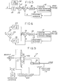
- FIG. 1 illustrates a conventional position command electrohydraulic servo control system 10 as comprising a valve actuator system 12 which includes an electrohydraulic valve coupled by an actuator to a load.
- the actuator system including the load, is characterized by an inertial mass and spring elasticity.
- a position transducer 14 is suitably mechanically coupled to the actuator and load to provide an electrical output signal X as a function of actual actuator and load position.
- a position command or reference signal R is fed to a summer 16 which provides an error signal E as a function of the difference between the command reference R and actual position X.
- the error signal E fed through a suitable amplifier having gain 18, controls operation of actuator system 12. It will be appreciated that summer 16 and gain 18 would typically be combined in a single analog amplifier.
- System 12 and transducer 14 may be of any suitable types, and indeed may be contained in a single assembly.
- Position command reference R may be generated by any suitable means, such as an operator joystick.
- FIG. 2 illustrates a modification to FIG. 1 in accordance with the invention for implementing velocity demand control.
- a velocity command signal V which may be generated by an operator joystick for example, is fed to an integrator 20, division of the signal V by the Laplace character "S" being a standard technique for illustrating an integration operation.
- the resulting signal is a facsimile position command signal R', and is fed to summer 16.
- the remainder of the circuit operates as in FIG. 1.
- a control system with position feedback is adapted to respond to velocity command input. Provision of integrator 20 is less expensive than replacing or supplementing the position transducer with a velocity transducer, and is more reliable (less noisy) than attempts to differentiate the output of the position transducer to provide velocity feedback.
- FIG. 3 illustrates a modification to FIG. 1 in accordance with the invention for implementing acceleration demand control.
- An acceleration demand signal A from an operator joystick for example, is fed to a double integrator 22.
- the output of integrator 22, which provides a facsimile position command signal R', is fed to summer 16.
- R' facsimile position command signal
- Fig. 5 illustrates a modification to the embodiment of Fig. 2 for reducing or eliminating such following error.
- the velocity command signal V is fed through integrator 20 to a first summer 26.
- the command signal V is also fed to a multiplier 28.
- the output of multiplier 28, which is an offset signal d' (Figs. 4 and 5), is fed to a second input of summer 26 where signal d ' is added to facsimile command signal R' to provide a corrected or composite facsimile position command signal R" to summer 16.
- the velocity signal V is multiplied by the factor K f/ (1 + T f S), wherein K f is a constant selected as a function of the following error, S is a Laplace character, and T f is a time constant selected to provide exponential initialization as shown in Fig. 4, and thus avoid system jerk.
- K f is a constant selected as a function of the following error
- S is a Laplace character
- T f is a time constant selected to provide exponential initialization as shown in Fig. 4, and thus avoid system jerk.
- FIG. 6 illustrates a third important aspect of the invention.
- the input velocity command signal V is first tested at 30 for equality with zero. If the velocity command signal V is non-zero, the signal V is integrated at 20 to provide the facsimile position signal R', which is fed to summer 16 as in FIG. 2. However, if the velocity command is equal to zero, logic is routed to the stage 32, which receives an X input from sensor 14, and the facsimile position command R' is set equal to X.
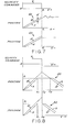
- FIG. 7 illustrates operation of the embodiment of FIG. 6 for eliminating end position creep due to following error.
- Velocity command V from an operator joystick or the like is uniform, and position signals R' and X increase uniformly as shown at 40.
- the actual load position X is observed by the operator to be at the desired location, and velocity command signal V is reduced to zero.
- Facsimile position command signal R' is accordingly horizontal and uniform.
- actual load position X is lagging facsimile position command R', so that the actual load continues to move under control of the error signal E (equal to R'-X).
- the facsimile position command signal R' is set equal to the actual position signal X at time tl when V equals zero.
- the actuator and load remain at the position desired by the operator.
- FIG. 8 illustrates operation of the system of FIG. 6 where the load reaches its limit position x 1 at time t l , which limit may be set by physical system constraints, for example.
- the operator continues to demand constant velocity until time t 2 , and then reverses direction.
- the facsimile position command R' continues to increase between times t and t 2 even though the load cannot follow.
- the position demand reverses slope after time t 2 , but does not intersect the limit position signal x 1 until time t 3 .
- load position X follows (but lags behind) facsimile position command R'.
- FIG. 6 Operation of the invention of FIG. 6 is illustrated in the lower graph 52 in FIG. 8.
- the facsimile position command signal R' is set equal to X. Thereafter, the facsimile position signal R' decreases from limit x l , and load position can follow. There is no dead time t 2 -t 3 as in illustration 50. It will be appreciated, of course, that the modification of FIG. 6 can be combined with that of FIG. 5 and/or FIG. 3 previously described.
- Controller 60 provides outputs to the solenoids of a valve 66, for example, which selectively feeds hydraulic fluid under pressure from a source and pump 68 to a drive cylinder 70.
- the piston of cylinder 70 is coupled to the load.
- Analog circuitry could also be employed in controller 60, as will be apparent to the artisan.
Landscapes
- Physics & Mathematics (AREA)
- General Physics & Mathematics (AREA)
- Engineering & Computer Science (AREA)
- Automation & Control Theory (AREA)
- Servomotors (AREA)
- Control Of Position Or Direction (AREA)
- Operation Control Of Excavators (AREA)
Applications Claiming Priority (4)
| Application Number | Priority Date | Filing Date | Title |
|---|---|---|---|
| US68426684A | 1984-12-20 | 1984-12-20 | |
| US06/684,265 US4612489A (en) | 1984-12-20 | 1984-12-20 | Power transmission |
| US684265 | 1984-12-20 | ||
| US684266 | 2000-10-06 |
Publications (2)
| Publication Number | Publication Date |
|---|---|
| EP0186092A1 true EP0186092A1 (fr) | 1986-07-02 |
| EP0186092B1 EP0186092B1 (fr) | 1990-01-31 |
Family
ID=27103294
Family Applications (1)
| Application Number | Title | Priority Date | Filing Date |
|---|---|---|---|
| EP19850116042 Expired EP0186092B1 (fr) | 1984-12-20 | 1985-12-16 | Transmission de puissance |
Country Status (5)
| Country | Link |
|---|---|
| EP (1) | EP0186092B1 (fr) |
| JP (1) | JPH0711149B2 (fr) |
| CN (1) | CN85109073A (fr) |
| AU (1) | AU579424B2 (fr) |
| DE (1) | DE3575798D1 (fr) |
Cited By (1)
| Publication number | Priority date | Publication date | Assignee | Title |
|---|---|---|---|---|
| EP0241161A1 (fr) * | 1986-04-03 | 1987-10-14 | Massey-Ferguson Services N.V. | Système et méthode de commande de soupape |
Families Citing this family (4)
| Publication number | Priority date | Publication date | Assignee | Title |
|---|---|---|---|---|
| CN100454197C (zh) * | 2005-11-03 | 2009-01-21 | 三一重工股份有限公司 | 工程机械行走速度的控制方法 |
| US8844280B2 (en) * | 2011-02-28 | 2014-09-30 | Caterpillar Inc. | Hydraulic control system having cylinder flow correction |
| CN102385311B (zh) * | 2011-09-15 | 2013-08-07 | 江苏科技大学 | 电液线速度数字伺服系统的控制方法 |
| JP6701709B2 (ja) * | 2015-12-14 | 2020-05-27 | 富士電機株式会社 | 制御装置、制御方法、制御プログラム、及びクレーンシステム |
Citations (3)
| Publication number | Priority date | Publication date | Assignee | Title |
|---|---|---|---|---|
| US2954514A (en) * | 1956-11-29 | 1960-09-27 | Gen Precision Inc | Servomechanism |
| US3775655A (en) * | 1972-09-15 | 1973-11-27 | Xerox Corp | Method and apparatus for transducer temperature compensation |
| EP0111064A2 (fr) * | 1982-09-14 | 1984-06-20 | Vickers Incorporated | Système de régulation de puissance |
Family Cites Families (2)
| Publication number | Priority date | Publication date | Assignee | Title |
|---|---|---|---|---|
| US3721882A (en) * | 1971-06-25 | 1973-03-20 | Sperry Rand Corp | Positioning system |
| JPS6121601Y2 (fr) * | 1981-03-02 | 1986-06-28 |
-
1985
- 1985-12-02 AU AU50570/85A patent/AU579424B2/en not_active Ceased
- 1985-12-16 DE DE8585116042T patent/DE3575798D1/de not_active Expired - Fee Related
- 1985-12-16 EP EP19850116042 patent/EP0186092B1/fr not_active Expired
- 1985-12-20 CN CN198585109073A patent/CN85109073A/zh active Pending
- 1985-12-20 JP JP28758785A patent/JPH0711149B2/ja not_active Expired - Lifetime
Patent Citations (3)
| Publication number | Priority date | Publication date | Assignee | Title |
|---|---|---|---|---|
| US2954514A (en) * | 1956-11-29 | 1960-09-27 | Gen Precision Inc | Servomechanism |
| US3775655A (en) * | 1972-09-15 | 1973-11-27 | Xerox Corp | Method and apparatus for transducer temperature compensation |
| EP0111064A2 (fr) * | 1982-09-14 | 1984-06-20 | Vickers Incorporated | Système de régulation de puissance |
Cited By (2)
| Publication number | Priority date | Publication date | Assignee | Title |
|---|---|---|---|---|
| EP0241161A1 (fr) * | 1986-04-03 | 1987-10-14 | Massey-Ferguson Services N.V. | Système et méthode de commande de soupape |
| US4907493A (en) * | 1986-04-03 | 1990-03-13 | Massey-Ferguson Services N. V. | Valve control system for hitch motor |
Also Published As
| Publication number | Publication date |
|---|---|
| JPH0711149B2 (ja) | 1995-02-08 |
| AU5057085A (en) | 1986-06-26 |
| CN85109073A (zh) | 1986-08-20 |
| AU579424B2 (en) | 1988-11-24 |
| DE3575798D1 (de) | 1990-03-08 |
| JPS61155523A (ja) | 1986-07-15 |
| EP0186092B1 (fr) | 1990-01-31 |
Similar Documents
| Publication | Publication Date | Title |
|---|---|---|
| US4612489A (en) | Power transmission | |
| US4643074A (en) | Power transmission | |
| US4714005A (en) | Power transmission | |
| US3699989A (en) | Feedback control apparatus | |
| CA1085493A (fr) | Systeme de commande a retroaction | |
| EP0414279A2 (fr) | Système pour le contrôle de l'attelage d'un tracteur | |
| GB2138969A (en) | Direct drive electro-hydraulic servo valves | |
| CA2293850C (fr) | Synchronisation des donnees fournies a l'actionneur des gouvernails marins | |
| JPS63186001A (ja) | 電気油圧式サーボシステム | |
| US5049799A (en) | High performance controller for variable displacement hydraulic motors | |
| US4882528A (en) | Digital servo system | |
| US4817498A (en) | Dynamic characteristic compensating device for electrical hydraulic servo actuator | |
| EP0186092B1 (fr) | Transmission de puissance | |
| US4864209A (en) | Negative feedback control system | |
| CA1271243A (fr) | Transmission d'un couple | |
| JPH0220842B2 (fr) | ||
| JPS6366604A (ja) | 動的制限を有するサ−ボル−プ制御方式 | |
| GB2348518A (en) | Acceleration based control system for speed governing | |
| JPH04151083A (ja) | ポペット弁の制御回路 | |
| JPH04351304A (ja) | 油圧駆動装置 | |
| JP2796828B2 (ja) | 圧力調整回路用調整装置 | |
| JPH0475113A (ja) | 制御装置 | |
| JP2847649B2 (ja) | 操作レバーの制御方法 | |
| EP0251535A2 (fr) | Systèmes d'actionnement redondants en parallèle | |
| US4924754A (en) | Circuit arrangement for a hydraulic drive in a position control circuit |
Legal Events
| Date | Code | Title | Description |
|---|---|---|---|
| PUAI | Public reference made under article 153(3) epc to a published international application that has entered the european phase |
Free format text: ORIGINAL CODE: 0009012 |
|
| AK | Designated contracting states |
Kind code of ref document: A1 Designated state(s): BE DE FR GB IT SE |
|
| 17P | Request for examination filed |
Effective date: 19861206 |
|
| 17Q | First examination report despatched |
Effective date: 19880606 |
|
| ITF | It: translation for a ep patent filed | ||
| GRAA | (expected) grant |
Free format text: ORIGINAL CODE: 0009210 |
|
| AK | Designated contracting states |
Kind code of ref document: B1 Designated state(s): BE DE FR GB IT SE |
|
| REF | Corresponds to: |
Ref document number: 3575798 Country of ref document: DE Date of ref document: 19900308 |
|
| ET | Fr: translation filed | ||
| PLBE | No opposition filed within time limit |
Free format text: ORIGINAL CODE: 0009261 |
|
| STAA | Information on the status of an ep patent application or granted ep patent |
Free format text: STATUS: NO OPPOSITION FILED WITHIN TIME LIMIT |
|
| 26N | No opposition filed | ||
| ITTA | It: last paid annual fee | ||
| PGFP | Annual fee paid to national office [announced via postgrant information from national office to epo] |
Ref country code: SE Payment date: 19931117 Year of fee payment: 9 |
|
| PGFP | Annual fee paid to national office [announced via postgrant information from national office to epo] |
Ref country code: BE Payment date: 19931124 Year of fee payment: 9 |
|
| PGFP | Annual fee paid to national office [announced via postgrant information from national office to epo] |
Ref country code: FR Payment date: 19941112 Year of fee payment: 10 |
|
| PGFP | Annual fee paid to national office [announced via postgrant information from national office to epo] |
Ref country code: DE Payment date: 19941125 Year of fee payment: 10 |
|
| PGFP | Annual fee paid to national office [announced via postgrant information from national office to epo] |
Ref country code: GB Payment date: 19941129 Year of fee payment: 10 |
|
| PG25 | Lapsed in a contracting state [announced via postgrant information from national office to epo] |
Ref country code: SE Effective date: 19941217 |
|
| PG25 | Lapsed in a contracting state [announced via postgrant information from national office to epo] |
Ref country code: BE Effective date: 19941231 |
|
| EAL | Se: european patent in force in sweden |
Ref document number: 85116042.4 |
|
| BERE | Be: lapsed |
Owner name: VICKERS INC. Effective date: 19941231 |
|
| EUG | Se: european patent has lapsed |
Ref document number: 85116042.4 |
|
| PG25 | Lapsed in a contracting state [announced via postgrant information from national office to epo] |
Ref country code: GB Effective date: 19951216 |
|
| GBPC | Gb: european patent ceased through non-payment of renewal fee |
Effective date: 19951216 |
|
| PG25 | Lapsed in a contracting state [announced via postgrant information from national office to epo] |
Ref country code: FR Effective date: 19960830 |
|
| PG25 | Lapsed in a contracting state [announced via postgrant information from national office to epo] |
Ref country code: DE Effective date: 19960903 |
|
| REG | Reference to a national code |
Ref country code: FR Ref legal event code: ST |