EP0251626B2 - System zum Übertragen von Audio-/Datensignalen zum Begleiten von übertragenen Videosignalen - Google Patents
System zum Übertragen von Audio-/Datensignalen zum Begleiten von übertragenen Videosignalen Download PDFInfo
- Publication number
- EP0251626B2 EP0251626B2 EP87305529A EP87305529A EP0251626B2 EP 0251626 B2 EP0251626 B2 EP 0251626B2 EP 87305529 A EP87305529 A EP 87305529A EP 87305529 A EP87305529 A EP 87305529A EP 0251626 B2 EP0251626 B2 EP 0251626B2
- Authority
- EP
- European Patent Office
- Prior art keywords
- audio
- section
- data
- bits
- frame
- Prior art date
- Legal status (The legal status is an assumption and is not a legal conclusion. Google has not performed a legal analysis and makes no representation as to the accuracy of the status listed.)
- Expired - Lifetime
Links
Images


Classifications
-
- H—ELECTRICITY
- H04—ELECTRIC COMMUNICATION TECHNIQUE
- H04N—PICTORIAL COMMUNICATION, e.g. TELEVISION
- H04N7/00—Television systems
- H04N7/04—Systems for the transmission of one television signal, i.e. both picture and sound, by a single carrier
Definitions
- the present invention relates to transmission of audio signals to accompany transmitted video signals, in which system the audio/data signals comprise a stream of digital elements formed into a plurality of frames, each frame comprising sections, namely a section to indicate a start of a frame, a section to contain control information, a section to contain additional data and a section to contain the audio/data information, whereby the audio signal is transmitted with the audio/data information section.
- the audio/data signals comprise a stream of digital elements formed into a plurality of frames, each frame comprising sections, namely a section to indicate a start of a frame, a section to contain control information, a section to contain additional data and a section to contain the audio/data information, whereby the audio signal is transmitted with the audio/data information section.
- a proposed transmission system for stereo signals to accompany conventional television transmissions provides a serial data stream partitioned into 728-bit frames, each transmitted in a millisecond.
- Each frame has: a first section of eight bits comprising a Frame Alignment Word (FAW) which marks the start of the frame; a second section of four bits which provide control information, being one flag bit (namely C o , which alternates between 0 and 1 every 8 milliseconds to determine odd and even frames over a 16 frame sequence) and three mode bits (namely C 1 , C 2 , and C 3 , which indicate the nature of the transmitted signal, e.g.
- FAW Frame Alignment Word
- interleaving is applied to the block of 720 bits which follow the FAW in order to ensure that adjacent bits are not transmitted seqentially so as to minimise the effect of multiple-bit errors.
- the interleaving pattern places data bits, which are adjacent in the frame structure as output by the television receiver, in positions at least 16 clock periods apart in the transmitted bit stream (i.e. at least 15 other bits occur between bits which are adjacent in the output frame structure).
- the interleave depth in this reference is 45 bits.
- the sound signals In the production of the sound signals, they are sampled at 32 kHz and coded initially with a resolution of 14 bits per sample. For transmission, the number of bits per sample is reduced to 10, using near-instantaneous companding, and one parity bit is added to the end of each 10-bit sample word for error detection and scale-factor signalling purposes, thereby resulting in the 11-bit words in the fourth section of the frame.
- the provision of the interleaving structure means that a parity bit may be received before some of the bits of the relevant word; accordingly, a frame is de-interleaved and stored before the range-determining operation is started.
- the system includes means to compare, after transmission, the non-interleaved sections of a number of adjacent frames, thereby to determine any errors in the non-interleaved sections (for example caused during transmission).
- the non-interleaved sections of a frame can be protected as well as, or even better, than the interleaved section while still providing simplified processing at the television receiver.
- FIG. 1 there is shown a transmission system 1 for the transmission of PAL System-I television signals accompanied by an additional stereo signal for enhanced audio reception.
- the system includes a transmission station 2 and a number of television receivers of which only one, referenced 3, is shown.
- Receiver 3 may be a conventional PAL television receiver connected with a decoder unit specifically designed to process the stereo signal and reproduce the stereo sound at, or for, the receiver; alternatively, the receiver may be specifically designed to process the stereo signal as well as, or instead of, processing the audio signal incorporated in the PAL System-I signal.
- Transmission station 2 has a studio 4 which provides a recording consisting of a channel of video signals (incorporating the normal audio component) in accordance with the System-I PAL standard, and a channel of stereo signals of a format as shown in Figure 2. Signals of this stereo channel are passed to an interleaver unit 5 which interleaves the audio data within each frame, and then passes the resultant signals to a transmitter 6 which broadcasts the PAL video channel and the stereo channel, the latter having a carrier frequency 6.552 MHz above the frequency of the transmitted vision carrier.
- the combined signal passes to a reception unit 7 at television receiver 3, and is separated out again into the PAL video channel (the subsequent processing of which at video processing unit 8 is conventional and therefore a description is not pertinent) and the stereo channel which is input to a de-interleaver unit 9 for re-arrangement of the bits, in the audio data section of each frame to their original sequence before input to interleaver unit 5.
- a range recovery unit 10 inspects each word and its corresponding parity bit in order to determine whether there is compatability, from which information it derives a three-bit range value for that frame.
- a parity correction unit 11 effects any necessary alterations to the words in view of the results of the compatability inspection
- a time expansion unit 12 increases the duration of the audio words to account for the other sections in a frame and the resultant signal passes to a loudspeaker unit 13 for output synchronized with display of the signal on the video channel at cathode ray tube screen 14.
- Figure 2 shows the structure of one frame of the signal in the stereo channel of transmission system 1 before interleaving.
- the sixty-four words in the audio information section are arranged such as to alternate between the two output signals of the stereo channel, i.e. the first, third and subsequent odd words are associated with output signal A (e.g. the lefthand side signal) of the stereo channel, while the second, fourth and subsequent even words are associated with output signal B (e.g. the righthand side signal) of the stereo channel.
- output signal A e.g. the lefthand side signal
- B e.g. the righthand side signal
- the system 1 is capable of transmitting signals other than stereo signals on this channel; thus for example this channel may carry mono audio signals (these being of higher quality than those incorporated with the conventional PAL video signal) in one language or more, or data signals representing information other than sound and optionally related to the television display.
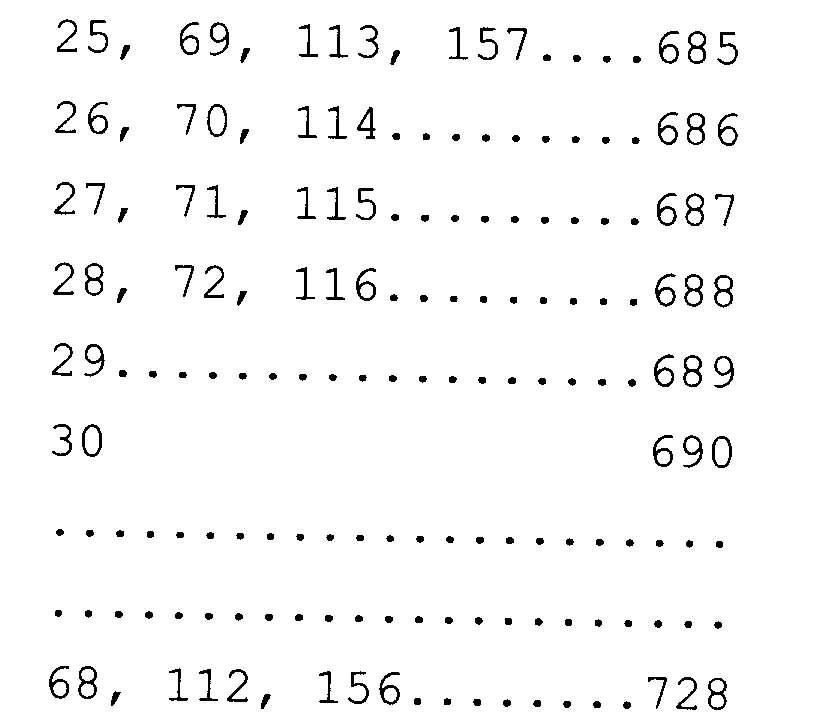
- the structure of the 728 bits in a frame is as shown in the Table 1 given below, in which the numbers relate to the original position before interleaving.
- the bits in the audio information section have been laid out in a lattice form to show clearly the interleaving structure; of course, in the signal itself, this section has a continuous sequence of bits formed by reading left to right along a row, the rows being taken from the top downwards.
- the de-interleave unit 9 has a switch unit to direct incoming frames alternately to two RAM stores, each of which corresponds to the arrangement shown in Figure 3 whereby a 11 by 64 RAM block 20 has a divide-by-11 counter 21, a divide-by-four counter 22 and a divide-by-16 counter 23.
- the divide-by-64 counter is formed of counter 23 and counter 22.
- the print clock pulse changes the number in counter 23 to 1 and the decoder selects row 4 while the decoder output of counter 21 selects column 0.
- the second clock pulse changes the number in counter 23 to 2, which is decoded as row 8
- the third clock pulse changes the number to 3 which is decoded as row 12, and so on. In this way rows 0,4,8,16 and so on to 60 are addressed in turn while column 0 continues to be addressed.
- the next clock pulse resets counter 23 to 0 and the overflow pulse clocks counter 21 to 1. Rows 0,4,8 16 and so on to 60 are now again addressed in turn but with column 1 addressed. This continues until row 60 column 10 has been written.
- the next clock pulse produces an overflow from counter 21 which clocks 1 into counter 22. The number is added to the row count of counter 23, so the addressed rows are row 1,5,9, 17 and so on to 61.
- the overflow from counter 21 changes the number in 22 to 2, and so on.
- the data bits are stored in the RAM in de-interleaved order and can be read out by simply addressing each of the rows in turn using the divide-by-64 counter formed by the divide-by-16 counter 23 and the divide-by-4 counter 22. Since the 11 bits of a word are read out in parallel, the divide-by-11 counter 21 is not needed for read-out and the same counter can therefore be used to address the second RAM which writes while the first is being read.
- FIG 4 a circuit diagram of the memory organization and address logic of a store 20 and its associated electronic circuits and components in greater detail than shown by Figure 3.
- Store 20 includes two 64 x 3 ROM's 30, 31, one being used for range recovery in mono signals, and one being used for range recovery in stereo signals.
- ROM associated with the RAM area
- ROM is used for range word testing.
- the use of ROM reduces the amount of chip area which would otherwise have to be employed in the range word test logic.
- the ROM information is held in binary form so that only three rather than six select lines need to be routed around the IC to the majority logic counters. This again is a saving in chip area.
- a ROM/RAM structure may be of a design so that every word of RAM also accesses a six bit word of ROM. By customising a ROM/RAM system only one row decoder needs to be included. By multiplexing the range test circuitry only one set of majority logic counters need be included in the integrated circuit.
- the information and parity bits of each word are transmitted in the correct order, i.e. the least-significant-bit first and the parity bit last.
- the value of its range bit can be determined and sent to the majority logic.
- all the received parity bits can be stored in the same column and the action of writing in that column indicates that the parity check can be made on the word in that row.
- the range bits are therefore determined in real-time rather than after the complete frame has been stored; so read-out can begin immediately and the store will be free by the time the third frame begins to arrive, thereby ensuring that a third store is unnecessary for the processing of stereo signals.
- a third store is necessary for the processing of "simultaneous dual - language reception" signals, but again the described arrangement provides a reduction in storage necessary, in that conventional processing techniques for such signals require four stores.
- the counter may be simply incremented when the input is say a "1" and no action taken when the input is in the alternative state.
- the output of the count can be checked to see if it is greater than a particular value e.g. half the number of input pulses. If it is greater, then the output is one state; if it is less, the majority is the alternative state.
- Sound muting which avoids unacceptable clicking of the loudspeaker may be achieved by shifting the output signal right or left with respect to the least significant bit by means of a parallel-to-serial output circuit programmed to shift left or right depending on whether a mute or demute was required.
- An alternative way of range recovery is to utilise a high speed processing system in order to calculate the correct range words during the time interval occupied by the frame alignment word, control bits, and auxiliary data. If the range bits could be calculated correctly during this interval, one less RAM is required than would otherwise be needed. Should this calculation period extend over into the transmitted frame alignment control bits and additional data interval, however, then an extra RAM would be necessary.
- the system has an additional timing circuit included. If one considers the locking circuit to be in two parts, the first part is a FAW detection circuit and the second part a Co bit detector (effectively a digital phase lock loop). Then the normal action of lock would be: firstly the frame alignment code acquires lock and enables the Co detections circuit to lock on to the Co bit waveform; secondly, when the Co and FAW acquisition circuits indicate that both these signals are acquired, the receiver is allowed to proceed with decoding sound.
- a FAW code circuit 40 generates an output indicating a valid frame alignment code pattern detection. This in turn starts a timing device 41 which times a period sufficient for the Co detector 42 to acquire lock under all useable signal conditions. At the end of this timing period, the Co detector is checked to see if a valid Co detection has taken place. If it has, no action is taken; but if it has not, the FAW detection circuitry is reset and a new frame alignment lock sequence initiated.
- Figure 6 shows appropriate waveforms.
Landscapes
- Engineering & Computer Science (AREA)
- Multimedia (AREA)
- Signal Processing (AREA)
- Error Detection And Correction (AREA)
- Transmission Systems Not Characterized By The Medium Used For Transmission (AREA)
- Television Receiver Circuits (AREA)
- Stereo-Broadcasting Methods (AREA)
- Television Systems (AREA)
- Reduction Or Emphasis Of Bandwidth Of Signals (AREA)
Claims (11)
- Verfahren zur Übertragung eines Audio/Daten-Signals zu einem übertragenen Videosignal, in welchem Verfahren das Audio/Daten-Signal einen Strom von Digital-Elementen (Bits) enthält, die eine Vielzahl von Rahmen bilden, wobei jeder Rahmen (Fig. 2) mindestens vier Abschnitte enthält, nämlich einen Abschnitt (FAW) zur Anzeige des Starts eines Rahmens, einen Abschnitt (C) mit Steuer-Informationen, einen Abschnitt (AD) mit Zusatzdaten und einen Abschnitt (A1, B1, A2, ..., B31, A32, B32), der die Audio/Daten-Information des Audio/Daten-Signals enthält,
wobei der Audio/Daten-Signal-Abschnitt des Audio/Daten-Signals als Multibit-Abtastworte kodiert ist und jedem dieser Worte ein Paritätsbit (P) zugeordnet ist, wobei das Paritätsbit (P) an das Ende eines jeden der Multibit-Abtastworte des Audiosignals angehängt ist und zur Fehler-Detektion und für Skalenfaktor-Signalisierungszwecke dient und nach dem Abtastwort übertragen wird, und wobei ohne Berücksichtigung des Paritätsbits die Anzahl der Bits per Abtastwort 10 ist,
und wobei nur der Audio/Daten-Informations-Abschnitt (A1, B1, A2, ..., B31, A32, B32) einschließlich des Paritätsbits (P), aber nicht der Anzeige-(FAW), Zusatzdaten-(AD) und Steuer-(C)-Abschnitt in einem verschachtelten Format übertragen wird, bei dem in jedem Rahmen alle digitalen Elemente innerhalb des gesamten Audio-/Daten-Informations-Abschnitts in einer unterschiedlichen aber zusammenhängenden Reihenfolge vorliegen (Tabelle 1), wobei jeder Rahmen aus 728 Bits besteht, der die Audio/Daten-Information enthaltende Abschnitt eine Länge von 704 Bit hat und die Verschachtelungs-Tiefe in diesem Abschnitt gleich der vierfachen Anzahl der Bits der Multibit-Abtastwortlänge einschließlich des zugehörigen Paritätsbits ist. - Verfahren nach Anspruch 1, bei dem das Audio-Signal mit 32kHz abgetastet und mit einer Anfangs-Auflösung von 14 Bit pro Abtastwert kodiert wird, wobei die Zahl der Bits pro Abtastwert durch die Benutzung einer Near-Instantaneous-Kompandierung reduziert wird.
- Verfahren nach Anspruch 1 oder 2, bei dem der Abschnitt mit der Audio/Daten-Information entsprechend der folgenden Tabelle verschachtelt wird:wobei die Zahlen sich auf die ursprüngliche Position vor der Verschachtelung beziehen.
- Fernseh-Empfänger (3) für ein Übertragungssystem (1) zur Bereitstellung eines Audio/Daten-Signals welches zu einem übertragenen Videosignal gehört, wobei der Fernseh-Empfänger (3) enthält:Mittel (7) zur Eingabe eines übertragenen Audio/Daten-Signals enthaltend einen Strom von Digital-Elementen (Bits), die eine Vielzahl von Rahmen bilden, wobei jeder Rahmen mindestens vier Abschnitte enthält, nämlich einen Abschnitt (FAW) zur Anzeige des Starts eines Rahmens, einen Abschnitt (C) mit Steuer-Informationen, einen Abschnitt (AD) mit Zusatzdaten und einen Abschnitt (A1, B1, A2, ..., B31, A32, B32), der die Audio/Daten-Information des Audio/Daten-Signals enthält;Mittel (13) zur Ausgabe des resultierenden Audio/Daten-Signals im Zusammenhang mit einem Videosignal, wobei der Audio/Daten-Signal-Abschnitt des empfangenen Audio/Daten-Signals als Multibit-Abtastworte kodiert ist und jedem dieser Worte ein Paritätsbit (P) zugeordnet ist, wobei das Paritätsbit (P) an ein jedes der Multibit-Abtastworte des Audiosignals angehängt ist und zur Fehler-Detektion und für Skalenfaktor-Signalisierungszwecke
dient und nach dem Abtastwort empfangen wird, und wobei ohne Berücksichtigung des Paritätsbits die Anzahl der Bits per Abtastwort 10 ist und der Fernseh-Empfänger ferner enthält:Mittel (9) zum Entschachteln nur des Audio/Daten-Informations-Abschnitts (A1, B1, A2, ..., B31, A32, B32) einschließlich des Paritätsbits (P), aber nicht des Anzeige-(FAW), Zusatzdaten-(AD) und Steuer-(C)-Abschnitts eines Rahmens, wobei die Entschachtelungs-Mittel (9) Mittel enthalten zur Änderung der Reihenfolge der digitalen Elemente des Audio-/Daten-Informations-Abschnitts innerhalb jedes ganzen, entsprechend eines vorbestimmten Zusammenhangs (Tabelle 1) übertragen Rahmens, um eine Reihenfolge für die Ausgabe durch den Fernseh-Empfänger (3) zu produzieren,
wobei jeder Rahmen aus 728 Bits besteht, der die Audio/Daten-Information enthaltende Abschnitt eine Länge von 704 Bit hat und die Entschachtelungs-Tiefe in diesem Abschnitt gleich der vierfachen Anzahl der Bits der Multibit-Abtastwortlänge einschließlich des zugehörigen Paritätsbits ist. - Fernseh-Empfänger nach Anspruch 4, bei dem die Entschachtelungs-Mittel (9) enthalten: Speichermittel (20) zum Speichern einer Vielzahl von Rahmen von Audio/Daten-Signalen, Zählermittel (21, 22, 23) zur Eingabe des Audio/Daten-Signals in die Speichermittel (20) und zur Ausgabe von den Speichermitteln (20), Logik-Schaltungsmittel zum Bewirken einer Rekonfiguration der Zählermittel zwischen einem Modus zur Eingabe der Signale in die Speichermittel und einem anderen Modus zu deren Ausgabe daraus.
- Fernseh-Empfänger nach Anspruch 4 oder 5, der enthält: Mittel (10) zum Bestimmen des Kompandierungsbereich-Werts für einen Rahmen des Audio/Daten-Signals, Kompandierungsbereich-Bestimmungsmittel zum Verarbeiten des Rahmens entsprechend seiner Eingabe darin, und Mittel zur Eingabe des resultierenden Audio/Daten-Signals im Zusammenhang mit dem Videosignal.
- Fernseh-Empfänger nach einem der Ansprüche 4 bis 6, der Mittel (12) enthält, um nach der Übertragung nicht verschachtelter Abschnitte eine Anzahl benachbarter Rahmen zu vergleichen um mögliche Fehler in den nicht verschachtelten Abschnitten zu ermitteln.
- Sender (2) für ein Übertragungssystem (1) zur Bereitstellung eines Audio/Daten-Signals, welches zu einem übertragenen Videosignal gehört, wobei der Sender (2) enthält:Mittel (7) zur Eingabe eines übertragenen Audio/Daten-Signals bestehend aus einem Strom von Digital-Elementen (Bits), die eine Vielzahl von Rahmen bilden, wobei jeder Rahmen mindestens vier Abschnitte enthält, nämlich einen Abschnitt (FAW) zur Anzeige des Starts eines Rahmens, einen Abschnitt (C) mit Steuer-Informationen, einen Abschnitt (AD) mit Zusatzdaten und einen Abschnitt (A1, B1, A2, ..., B31, A32, B32), der die Audio/Daten-Information des Audio/Daten-Signals enthält,
wobei der Audio/Daten-Signal-Abschnitt des empfangenen Audio/Daten-Signals als Multibit-Abtastworte kodiert ist und jedem dieser Worte ein Paritätsbit (P) zugeordnet ist, wobei das Paritätsbit (P) an ein jedes der Multibit-Abtastworte des Audiosignals angehängt ist und zur Fehler-Detektion und für Skalenfaktor-Signalisierungszwecke dient und nach dem Abtastwort übertragen wird, und wobei ohne Berücksichtigung des Paritätsbits die Anzahl der Bits per Abtastwort 10 ist und der Sender (2) enthält:Mittel (5) zum Verschachteln nur des Audio/Daten-Informations-Abschnitts (A1, B1, A2, ..., B31, A32, B32) einschließlich des Paritätsbits (P), aber nicht des Anzeige-(FAW), Zusatzdaten-(AD) und Steuer-(C)-Abschnitts eines Rahmens, wobei die Verschachtelungs-Mittel (5) Mittel enthalten zur Änderung der Reihenfolge der digitalen Elemente des Audio-/Daten-Informations-Abschnitts innerhalb jedes ganzen, entsprechend eines vorbestimmten Zusammenhangs (Tabelle 1) Eingangs-Rahmens, um eine Reihenfolge für die Übertragung zu produzieren,
wobei jeder Rahmen aus 728 Bits besteht, der die Audio/Daten-Information enthaltende Abschnitt eine Länge von 704 Bit hat und die Verschachtelungs-Tiefe in diesem Abschnitt gleich der vierfachen Anzahl der Bits der Multibit-Abtastwortlänge einschließlich des zugehörigen Paritätsbits ist. - Sender nach Anspruch 8, bei dem die Entschachtelungs-Mittel (9) enthalten: Speichermittel zum Speichern einer Vielzahl von Rahmen von Audio/Daten-Signalen, Zählermittel zur Eingabe des Audio/Daten-Signals in die Speichermittel und zur Ausgabe von den Speichermitteln, Logik-Schaltungsmittel zum Bewirken einer Rekonfiguration der Zählermittel zwischen einem Modus zur Eingabe der Signale in die Speichermittel und einem anderen Modus zu deren Ausgabe daraus.
- Audio/Daten-Signal zu einem übertragenen Videosignal, wobei das Audio/Daten-Signal einen Strom von Digital-Elementen (Bits) enthält, die eine Vielzahl von Rahmen bilden, wobei jeder Rahmen (Fig. 2) mindestens vier Abschnitte enthält, nämlich einen Abschnitt (FAW) zur Anzeige des Starts eines Rahmens, einen Abschnitt (C) mit Steuer-Informationen, einen Abschnitt (AD) mit Zusatzdaten und einen Abschnitt (A1, B1, A2, ..., B31, A32, B32), der die Audio/Daten-Information des Audio/Daten-Signals enthält,
wobei der Audio/Daten-Signal-Abschnitt des Audio/Daten-Signals als Multibit-Abtastworte kodiert ist und jedem dieser Worte ein Paritätsbit (P) zugeordnet ist, wobei das Paritätsbit (P) an das Ende eines jeden der Multibit-Abtastworte des Audiosignals angehängt ist und zur Fehler-Detektion und für Skalenfaktor-Signalisierungszwecke dient und nach dem Abtastwort angeordnet ist, und wobei ohne Berücksichtigung des Paritätsbits die An-zahl der Bits per Abtastwort 10 ist,
und wobei nur der Audio/Daten-Informations-Abschnitt (A1, B1, A2, ..., B31, A32, B32) einschließlich des Paritätsbits (P), aber nicht der Anzeige-(FAW), Zusatzdaten-(AD) und Steuer-(C)-Abschnitt verschachtelt ist, so daß in jedem Rahmen alle digitalen Elemente innerhalb des gesamten Audio-/Daten-Informations-Abschnitts in einer unterschiedlichen, aber zusammenhängenden Reihenfolge vorliegen (Tabelle 1),
wobei jeder Rahmen aus 728 Bits besteht, der die Audio/Daten-Information enthaltende Abschnitt eine Länge von 704 Bit hat und die Verschachtelungs-Tiefe in diesem Abschnitt gleich der vierfachen Anzahl der Bits der Multibit-Abtastwortlänge einschließlich des zugehörigen Paritätsbits ist. - Verwendung des Audio/Daten-Signals nach Anspruch 10 in einem Fernseh-Empfänger zum Erzeugen eines wahrnehmbaren Audio/Daten-Signals.
Applications Claiming Priority (2)
| Application Number | Priority Date | Filing Date | Title |
|---|---|---|---|
| GB8615308 | 1986-06-23 | ||
| GB8615308A GB2191914B (en) | 1986-06-23 | 1986-06-23 | Transmission system for audio/data signals |
Publications (4)
| Publication Number | Publication Date |
|---|---|
| EP0251626A2 EP0251626A2 (de) | 1988-01-07 |
| EP0251626A3 EP0251626A3 (en) | 1988-10-05 |
| EP0251626B1 EP0251626B1 (de) | 1994-01-12 |
| EP0251626B2 true EP0251626B2 (de) | 2000-12-06 |
Family
ID=10599956
Family Applications (2)
| Application Number | Title | Priority Date | Filing Date |
|---|---|---|---|
| EP87305529A Expired - Lifetime EP0251626B2 (de) | 1986-06-23 | 1987-06-22 | System zum Übertragen von Audio-/Datensignalen zum Begleiten von übertragenen Videosignalen |
| EP87305531A Expired - Lifetime EP0257739B1 (de) | 1986-06-23 | 1987-06-22 | Fernsehempfänger für ein Übertragungssystem zum Liefern von Audio-/Datensignalen zum Begleiten der Übertragenen Videosignale |
Family Applications After (1)
| Application Number | Title | Priority Date | Filing Date |
|---|---|---|---|
| EP87305531A Expired - Lifetime EP0257739B1 (de) | 1986-06-23 | 1987-06-22 | Fernsehempfänger für ein Übertragungssystem zum Liefern von Audio-/Datensignalen zum Begleiten der Übertragenen Videosignale |
Country Status (7)
| Country | Link |
|---|---|
| EP (2) | EP0251626B2 (de) |
| AU (2) | AU587552B2 (de) |
| FI (2) | FI872767A7 (de) |
| GB (1) | GB2191914B (de) |
| HK (2) | HK1595A (de) |
| NO (2) | NO872595L (de) |
| NZ (3) | NZ220774A (de) |
Families Citing this family (7)
| Publication number | Priority date | Publication date | Assignee | Title |
|---|---|---|---|---|
| EP0320544A1 (de) * | 1987-12-15 | 1989-06-21 | Ferguson Limited | Fernsehübertragungssystem mit Stereoton |
| DE3789234T3 (de) * | 1987-12-15 | 1998-07-23 | Ferguson Ltd | Fernsehübertragungssystem mit Stereoton. |
| GB2233860B (en) * | 1989-07-13 | 1993-10-27 | Stc Plc | Communications systems |
| EP0701253B1 (de) * | 1994-08-10 | 2002-01-30 | Matsushita Electric Industrial Co., Ltd. | Aufzeichnungs- und Wiedergabegerät für kodierten Datenstrom |
| KR100193846B1 (ko) | 1996-10-02 | 1999-06-15 | 윤종용 | 인터리브 리드 어드레스 생성기 |
| GB2327578A (en) * | 1997-07-18 | 1999-01-27 | Nokia Mobile Phones Ltd | Convolutional interleaver for preventing the transmission of unwanted data |
| US9028751B2 (en) | 2009-07-09 | 2015-05-12 | Odotech Inc. | System and method for dynamically controlling odor emission |
Family Cites Families (5)
| Publication number | Priority date | Publication date | Assignee | Title |
|---|---|---|---|---|
| US3795763A (en) * | 1972-04-18 | 1974-03-05 | Communications Satellite Corp | Digital television transmission system |
| US4281355A (en) * | 1978-02-01 | 1981-07-28 | Matsushita Electric Industrial Co., Ltd. | Digital audio signal recorder |
| JPS5845613A (ja) * | 1981-09-11 | 1983-03-16 | Hitachi Ltd | Pcmレコ−ダ |
| JPS5885938A (ja) * | 1981-11-16 | 1983-05-23 | Toshiba Corp | 光学的情報記録方式 |
| JPH0654973B2 (ja) * | 1983-11-09 | 1994-07-20 | ソニー株式会社 | Catvラインを使用したデジタル信号の伝送装置 |
-
1986
- 1986-06-23 GB GB8615308A patent/GB2191914B/en not_active Expired - Lifetime
-
1987
- 1987-06-19 NO NO872595A patent/NO872595L/no unknown
- 1987-06-19 NZ NZ220774A patent/NZ220774A/xx unknown
- 1987-06-19 NO NO872594A patent/NO171089C/no not_active IP Right Cessation
- 1987-06-19 NZ NZ220773A patent/NZ220773A/xx unknown
- 1987-06-19 NZ NZ220775A patent/NZ220775A/xx unknown
- 1987-06-22 FI FI872767A patent/FI872767A7/fi not_active Application Discontinuation
- 1987-06-22 FI FI872766A patent/FI86129C/fi not_active IP Right Cessation
- 1987-06-22 EP EP87305529A patent/EP0251626B2/de not_active Expired - Lifetime
- 1987-06-22 EP EP87305531A patent/EP0257739B1/de not_active Expired - Lifetime
- 1987-06-23 AU AU74613/87A patent/AU587552B2/en not_active Expired
- 1987-06-23 AU AU74614/87A patent/AU587553B2/en not_active Expired
-
1995
- 1995-01-05 HK HK1595A patent/HK1595A/en not_active IP Right Cessation
-
1997
- 1997-02-05 HK HK13697A patent/HK13697A/en not_active IP Right Cessation
Also Published As
| Publication number | Publication date |
|---|---|
| EP0257739B1 (de) | 1992-10-07 |
| FI86129B (fi) | 1992-03-31 |
| AU587553B2 (en) | 1989-08-17 |
| GB2191914A (en) | 1987-12-23 |
| GB8615308D0 (en) | 1986-07-30 |
| FI872767A0 (fi) | 1987-06-22 |
| NO171089C (no) | 1993-01-20 |
| EP0257739A2 (de) | 1988-03-02 |
| NO872594L (no) | 1987-12-28 |
| NZ220775A (en) | 1990-03-27 |
| NO872595L (no) | 1987-12-28 |
| NO872594D0 (no) | 1987-06-19 |
| HK13697A (en) | 1997-02-14 |
| FI872766A7 (fi) | 1987-12-24 |
| AU587552B2 (en) | 1989-08-17 |
| NO171089B (no) | 1992-10-12 |
| FI872766A0 (fi) | 1987-06-22 |
| EP0251626B1 (de) | 1994-01-12 |
| EP0251626A2 (de) | 1988-01-07 |
| AU7461487A (en) | 1987-12-24 |
| NZ220773A (en) | 1990-03-27 |
| NO872595D0 (no) | 1987-06-19 |
| AU7461387A (en) | 1987-12-24 |
| GB2191914B (en) | 1991-03-20 |
| FI86129C (fi) | 1992-07-10 |
| EP0257739A3 (en) | 1988-10-12 |
| HK1595A (en) | 1995-01-13 |
| FI872767A7 (fi) | 1987-12-24 |
| NZ220774A (en) | 1990-03-27 |
| EP0251626A3 (en) | 1988-10-05 |
Similar Documents
| Publication | Publication Date | Title |
|---|---|---|
| US5420640A (en) | Memory efficient method and apparatus for sync detection | |
| US3927250A (en) | Television system with transmission of auxiliary information | |
| US4953022A (en) | Teletext decoders | |
| EP0251626B2 (de) | System zum Übertragen von Audio-/Datensignalen zum Begleiten von übertragenen Videosignalen | |
| KR950009455B1 (ko) | 음성 디코더 | |
| US4963968A (en) | Method and apparatus for validating teletext data | |
| JP3169832B2 (ja) | フレーム構成のデジタル信号のデータ誤り訂正方法及びそれに利用する装置 | |
| EP0320545B2 (de) | Fernsehübertragungssystem mit Stereoton | |
| JPH06237422A (ja) | 文字表示装置 | |
| KR100649144B1 (ko) | 다중 스탠다드 비디오 데이터 포착을 위한 방법 및 장치 | |
| EP0320544A1 (de) | Fernsehübertragungssystem mit Stereoton | |
| JP3320712B2 (ja) | テレテキスト・デコーダ | |
| EP0514041B1 (de) | Digitaler Datendekodierer mit durch Fehlernachricht beeinflusster Übertragungsmodusselektion | |
| JPS6231553B2 (de) | ||
| JP3103098B2 (ja) | Pcm音声デコーダ装置 | |
| KR100255440B1 (ko) | 제어 기능 동기 방법 및 장치 | |
| US4535362A (en) | Method of transferring data in a television receiver | |
| JPS6133305B2 (de) | ||
| JPH01213037A (ja) | 音声デコーダ | |
| KR100188142B1 (ko) | 콘벌루션 디인터리버의 빠른 동기화를 위한 메모리 억세스 방법 | |
| JPH0566778B2 (de) | ||
| JPS6245759B2 (de) | ||
| Pim | Teletext | |
| GB2269971A (en) | Page memory clearance selectively disabled in teletext decoder | |
| JPH04245877A (ja) | 音声信号処理回路 |
Legal Events
| Date | Code | Title | Description |
|---|---|---|---|
| PUAI | Public reference made under article 153(3) epc to a published international application that has entered the european phase |
Free format text: ORIGINAL CODE: 0009012 |
|
| AK | Designated contracting states |
Kind code of ref document: A2 Designated state(s): BE GB NL SE |
|
| PUAL | Search report despatched |
Free format text: ORIGINAL CODE: 0009013 |
|
| RAP1 | Party data changed (applicant data changed or rights of an application transferred) |
Owner name: FERGUSON LIMITED |
|
| AK | Designated contracting states |
Kind code of ref document: A3 Designated state(s): BE GB NL SE |
|
| 17P | Request for examination filed |
Effective date: 19890116 |
|
| 17Q | First examination report despatched |
Effective date: 19910402 |
|
| GRAA | (expected) grant |
Free format text: ORIGINAL CODE: 0009210 |
|
| AK | Designated contracting states |
Kind code of ref document: B1 Designated state(s): BE GB NL SE |
|
| PLBI | Opposition filed |
Free format text: ORIGINAL CODE: 0009260 |
|
| 26 | Opposition filed |
Opponent name: INTERESSENGEMEINSCHAFT FUER RUNDFUNKSCHUTZRECHTE E Effective date: 19941011 |
|
| EAL | Se: european patent in force in sweden |
Ref document number: 87305529.7 |
|
| NLR1 | Nl: opposition has been filed with the epo |
Opponent name: INTERESSENGEMEINSCHAFT FUER RUNDFUNKSCHUTZRECHTE E |
|
| PLAB | Opposition data, opponent's data or that of the opponent's representative modified |
Free format text: ORIGINAL CODE: 0009299OPPO |
|
| R26 | Opposition filed (corrected) |
Opponent name: INTERESSENGEMEINSCHAFT FUER RUNDFUNKSCHUTZRECHTE E Effective date: 19941011 |
|
| NLR1 | Nl: opposition has been filed with the epo |
Opponent name: INTERESSENGEMEINSCHAFT FUER RUNDFUNKSCHUTZRECHTE E |
|
| RAP2 | Party data changed (patent owner data changed or rights of a patent transferred) |
Owner name: THOMSON MULTIMEDIA SALES UK LIMITED |
|
| PLAW | Interlocutory decision in opposition |
Free format text: ORIGINAL CODE: EPIDOS IDOP |
|
| NLT2 | Nl: modifications (of names), taken from the european patent patent bulletin |
Owner name: THOMSON MULTIMEDIA SALES UK LIMITED |
|
| APAC | Appeal dossier modified |
Free format text: ORIGINAL CODE: EPIDOS NOAPO |
|
| APAE | Appeal reference modified |
Free format text: ORIGINAL CODE: EPIDOS REFNO |
|
| APAC | Appeal dossier modified |
Free format text: ORIGINAL CODE: EPIDOS NOAPO |
|
| APCC | Communication from the board of appeal sent |
Free format text: ORIGINAL CODE: EPIDOS OBAPO |
|
| APCC | Communication from the board of appeal sent |
Free format text: ORIGINAL CODE: EPIDOS OBAPO |
|
| APAC | Appeal dossier modified |
Free format text: ORIGINAL CODE: EPIDOS NOAPO |
|
| PLAW | Interlocutory decision in opposition |
Free format text: ORIGINAL CODE: EPIDOS IDOP |
|
| PUAH | Patent maintained in amended form |
Free format text: ORIGINAL CODE: 0009272 |
|
| STAA | Information on the status of an ep patent application or granted ep patent |
Free format text: STATUS: PATENT MAINTAINED AS AMENDED |
|
| 27A | Patent maintained in amended form |
Effective date: 20001206 |
|
| AK | Designated contracting states |
Kind code of ref document: B2 Designated state(s): BE GB NL SE |
|
| NLR2 | Nl: decision of opposition | ||
| NLR3 | Nl: receipt of modified translations in the netherlands language after an opposition procedure | ||
| NLT1 | Nl: modifications of names registered in virtue of documents presented to the patent office pursuant to art. 16 a, paragraph 1 |
Owner name: THOMSON MULTIMEDIA SALES UK LIMITED |
|
| REG | Reference to a national code |
Ref country code: GB Ref legal event code: IF02 |
|
| APAH | Appeal reference modified |
Free format text: ORIGINAL CODE: EPIDOSCREFNO |
|
| PGFP | Annual fee paid to national office [announced via postgrant information from national office to epo] |
Ref country code: GB Payment date: 20060515 Year of fee payment: 20 |
|
| PGFP | Annual fee paid to national office [announced via postgrant information from national office to epo] |
Ref country code: NL Payment date: 20060619 Year of fee payment: 20 |
|
| PGFP | Annual fee paid to national office [announced via postgrant information from national office to epo] |
Ref country code: SE Payment date: 20060627 Year of fee payment: 20 |
|
| PGFP | Annual fee paid to national office [announced via postgrant information from national office to epo] |
Ref country code: BE Payment date: 20060628 Year of fee payment: 20 |
|
| PG25 | Lapsed in a contracting state [announced via postgrant information from national office to epo] |
Ref country code: NL Free format text: LAPSE BECAUSE OF EXPIRATION OF PROTECTION Effective date: 20070622 |
|
| REG | Reference to a national code |
Ref country code: GB Ref legal event code: PE20 |
|
| EUG | Se: european patent has lapsed | ||
| NLV7 | Nl: ceased due to reaching the maximum lifetime of a patent |
Effective date: 20070622 |
|
| PG25 | Lapsed in a contracting state [announced via postgrant information from national office to epo] |
Ref country code: GB Free format text: LAPSE BECAUSE OF EXPIRATION OF PROTECTION Effective date: 20070621 |
|
| BE20 | Be: patent expired |
Owner name: *THOMSON MULTIMEDIA SALES UK LTD Effective date: 20070622 |