EP0251780A1 - Das Aufbringen von Heissabziehbildern mittels eines Übertragungskissens - Google Patents
Das Aufbringen von Heissabziehbildern mittels eines Übertragungskissens Download PDFInfo
- Publication number
- EP0251780A1 EP0251780A1 EP87305827A EP87305827A EP0251780A1 EP 0251780 A1 EP0251780 A1 EP 0251780A1 EP 87305827 A EP87305827 A EP 87305827A EP 87305827 A EP87305827 A EP 87305827A EP 0251780 A1 EP0251780 A1 EP 0251780A1
- Authority
- EP
- European Patent Office
- Prior art keywords
- pad
- transfer
- platen
- design layer
- article
- Prior art date
- Legal status (The legal status is an assumption and is not a legal conclusion. Google has not performed a legal analysis and makes no representation as to the accuracy of the status listed.)
- Granted
Links
- 238000012546 transfer Methods 0.000 title claims abstract description 112
- 238000013461 design Methods 0.000 title claims abstract description 52
- 238000010438 heat treatment Methods 0.000 claims abstract description 62
- 239000000853 adhesive Substances 0.000 claims abstract description 21
- 230000001070 adhesive effect Effects 0.000 claims abstract description 21
- 238000000034 method Methods 0.000 claims description 26
- 238000003825 pressing Methods 0.000 claims description 7
- 238000000926 separation method Methods 0.000 claims description 3
- 238000013459 approach Methods 0.000 claims description 2
- 239000000919 ceramic Substances 0.000 abstract description 4
- 239000010410 layer Substances 0.000 description 37
- 239000000463 material Substances 0.000 description 11
- 239000012790 adhesive layer Substances 0.000 description 6
- 230000008569 process Effects 0.000 description 6
- 239000012530 fluid Substances 0.000 description 5
- 238000004519 manufacturing process Methods 0.000 description 3
- 241000252254 Catostomidae Species 0.000 description 2
- 230000008901 benefit Effects 0.000 description 2
- 238000010276 construction Methods 0.000 description 2
- 238000005034 decoration Methods 0.000 description 2
- 229920002379 silicone rubber Polymers 0.000 description 2
- 239000004945 silicone rubber Substances 0.000 description 2
- 230000007480 spreading Effects 0.000 description 2
- 238000003892 spreading Methods 0.000 description 2
- 239000002699 waste material Substances 0.000 description 2
- 230000004913 activation Effects 0.000 description 1
- 230000008859 change Effects 0.000 description 1
- 230000001427 coherent effect Effects 0.000 description 1
- 230000001627 detrimental effect Effects 0.000 description 1
- 230000000694 effects Effects 0.000 description 1
- 238000005485 electric heating Methods 0.000 description 1
- 238000002474 experimental method Methods 0.000 description 1
- 238000002372 labelling Methods 0.000 description 1
- 239000002184 metal Substances 0.000 description 1
- 238000009828 non-uniform distribution Methods 0.000 description 1
- 238000007645 offset printing Methods 0.000 description 1
- 230000008707 rearrangement Effects 0.000 description 1
- 230000003252 repetitive effect Effects 0.000 description 1
- 239000007787 solid Substances 0.000 description 1
Images


Classifications
-
- B—PERFORMING OPERATIONS; TRANSPORTING
- B44—DECORATIVE ARTS
- B44C—PRODUCING DECORATIVE EFFECTS; MOSAICS; TARSIA WORK; PAPERHANGING
- B44C1/00—Processes, not specifically provided for elsewhere, for producing decorative surface effects
- B44C1/16—Processes, not specifically provided for elsewhere, for producing decorative surface effects for applying transfer pictures or the like
- B44C1/165—Processes, not specifically provided for elsewhere, for producing decorative surface effects for applying transfer pictures or the like for decalcomanias; sheet material therefor
- B44C1/17—Dry transfer
- B44C1/1712—Decalcomanias applied under heat and pressure, e.g. provided with a heat activable adhesive
- B44C1/172—Decalcomanias provided with a layer being specially adapted to facilitate their release from a temporary carrier
-
- B—PERFORMING OPERATIONS; TRANSPORTING
- B65—CONVEYING; PACKING; STORING; HANDLING THIN OR FILAMENTARY MATERIAL
- B65C—LABELLING OR TAGGING MACHINES, APPARATUS, OR PROCESSES
- B65C9/00—Details of labelling machines or apparatus
- B65C9/20—Gluing the labels or articles
- B65C9/24—Gluing the labels or articles by heat
- B65C9/25—Gluing the labels or articles by heat by thermo-activating the glue
-
- B—PERFORMING OPERATIONS; TRANSPORTING
- B65—CONVEYING; PACKING; STORING; HANDLING THIN OR FILAMENTARY MATERIAL
- B65C—LABELLING OR TAGGING MACHINES, APPARATUS, OR PROCESSES
- B65C9/00—Details of labelling machines or apparatus
- B65C9/26—Devices for applying labels
- B65C9/36—Wipers; Pressers
Definitions
- This invention relates to the decoration or other marking of articles by applying design layers from heat-release transfers to surfaces of the articles by means of a deformable transfer pad.
- Such transfers comprise a thin film-like design layer which is separable from a backing sheet which supports it prior to use.
- the design layer is secured to the backing sheet, in manufacture of the transfer, by some form of adhesive material which can be activated in use to permit separation.
- an adhesive layer may be provided covering the design layer.
- the design layer may be adhered to an article by activated adhesive provided on one side or the other of the design layer.
- a deformable pad for carrying the design layer from the backing sheet and apply it to the article.
- a pad can suitably be of a silicone rubber material and be shaped to present a domed working surface, similar to pads well known in applying decorative colour to articles in off-set printing of ceramic tableware.
- U.S. Patent No. 4 511 425 This is concerned with labelling containers.
- the adhesive layers of the transfers are activated by heat from a hot platen on which the transfers are presented to the transfer pad.
- the transfer pad is heated in addition to the platen (though to a lower temperature than the platen) in order to maintain the activated adhesive tacky during carriage of the design layer from its backing sheet to a container to be labelled.
- Various ways of heating the pad internally are described, and it is also suggested that the pad might be heated by radiant heaters.
- the pad might be heated by pressing it periodically against the hot label-heating platen, though the rider is added that "the use of an additional (internal) heating element is generally preferred since it affords a greater degree of temperature control and is a more reliable method of maintaining the pad at the required temperature levels".
- the invention provides a method of applying a design layer from a heat-release transfer to a surface of an article utilising a deformable transfer pad, the method comprising heating the surface of the transfer pad by bringing together the pad and a pad-heating surface at a suitable elevated temperature and separating the pad and the surface after a suitable heating period, pressing together the heated pad and a heat-release transfer presented on a platen with at least the adhesive between the design layer and the backing sheet of the transfer not yet activated and maintaining the pad pressed against the transfer for sufficient time for heat from the pad to activate the adhesive of the transfer, separating the pad and the platen with the design layer of the transfer attached to the surface of the pad and with the backing sheet remaining on the platen, pressing together the pad and an article to be decorated to apply the design layer to the surface of the article, and separating the pad and the article leaving the design layer adhered to the article.
- the invention provides apparatus suitable for use in applying a design layer from a heat-release transfer to a surface of an article in performance of a method as set out in the last preceding paragraph, the apparatus comprising a deformable transfer pad, pad-heating means presenting a pad-heating surface, heating means arranged to heat the pad-heating means to maintain the pad-heating surface at an elevated temperature, a transfer-presenting platen, an article support, and mounting means supporting the pad, the pad-heating means, the platen and the article support and enabling relative movements of approach and separation to be effected:
- the pad-heating surface can be a flat surface of a heated plate against which the pad is pressed to spread a working area of the surface of the pad over the plate.
- the plate can conveniently be maintained at a substantially constant temperature by means of thermostatically-controlled electrical heating elements heating the plate conductively.
- the temperature of the transfer-presenting platen may be above ambient temperature in continuing performance of the method; each time the hot pad engages a transfer on the platen some heat will be transferred into the platen.
- a rise in temperature of the platen need not be detrimental to the process, provided it is not such that a significant heating effect on the transfers occurs; what matters principally is that in performance of the method the transfers do not become heated by the platen sufficiently for their adhesive to be activated, and the transfers so to lose their structural coherence, prior to being engaged by the pad.
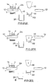
- Apparatus suitable for use in decorating articles of ceramic ware using heat-release transfers in a repetitive production process comprises (Figure 1) a horizontally-reciprocable transfer-presenting platen 10, a horizontally-reciprocable pad-heating platen 12, a vertically-reciprocable transfer-placing head 14, a cassette 16 for a stack of transfers T to be taken up one at a time by the placing head 14, a vertically-reciprocable transfer pad 18, and a ware-presenting turntable 20 comprising a plurality of circumferentially-spaced ware supports 22.
- the apparatus comprises also a vertically-reciprocable brush 24 which in a lowered position is arranged to sweep the surface of the presenting platen 10, as the latter moves therebeneath, and a collecting bin 26 to collect waste backing sheets B ( Figures 2(f) to 2(i)) swept from the platen 10 by the brush 24.
- the mounting means comprises also a vertical shaft 21 supporting the turntable 20 for rotational indexing movements of the turntable to present the ware supports 22 in turn beneath the transfer pad 18.
- the presenting platen 10 and the heating platen 12 are mounted in common on a horizontal slideway 11 of the mounting means, and the apparatus comprises operating means (not shown but of a conventional kind) for effecting required independent movements of them along the slideway.
- the apparatus comprises operating means of a conventional kind for effecting vertical reciprocation of the placing head 14 and of the transfer pad 18, and indexing of the turntable 20. Actuation of the various operating means in timed sequence, in a continuously repeated operating cycle, is controlled automatically by the apparatus in a conventional manner.
- the presenting platen 10 comprises a smooth and flat horizontal top surface.
- the pad 18 is maintained hot and the metal presenting platen 10 becomes incidentally warmed from repeated brief engagements by the pad.
- electric heating elements (not shown) are built into the platen so that the platen can be warmed initially. Once operation of the apparatus is under way, the heating elements are switched off.
- a flat pad-heating surface presented by the heating platen 12 is, on the other hand, maintained hot throughout use by conductive heating from thermostatically-controlled electrical heating elements 13 within the platen.
- the transfer-placing head 14 comprises a plurality of suckers whereby the surface of a transfer T can be gripped for lifting by the head from the cassette 16. Vacuum applied to the suckers for that operation can be released to allow the transfer to be put down on to the top surface of the presenting platen 10.
- the presenting platen 10 is arranged with airways leading to perforations in its top surface, allowing vacuum to be applied by the apparatus to hold the transfer backing sheet down to the surface of the platen when required during operation.
- the transfer pad 18 is of a suitably resiliently deformable silicone rubber material, and is shaped to present (facing downwardly) a domed working area of its surface.
- the precise pad shape is selected to suit the surface contours of the ware to be decorated.
- the placing head 14 is seen to be gripping a transfer T in a raised position in registry above the presenting platen 10.
- An article of ware W is mounted on one of the ware supports 22 in registry beneath the transfer pad 18.
- the pad 18 is in a raised position.
- the brush 24 is also in a raised position, so as to be well clear of the top surface of the presenting platen 10.
- Figure 2(b) shows the placing head 14 lowered to position the transfer T (with its design layer D uppermost) on the presenting platen 10.
- the transfer pad 18 is shown lowered and pressed against the heating platen 12; the pad and the heating platen are pressed together sufficiently for the whole working area of the pad to be spread over the surface of the platen.
- the pad 18 is maintained pressed against the heating platen for a suitable length of time. That heating period depends upon many different factors, and will usually have to be determined by experiment in each case. However, in one example of the process the platen surface is maintained at a temperature of about 180°C and the pad heating period is approximately two seconds in order to restore the pad surface temperature from around 105°C to around 125°C, the required decal-activating temperature in that case being 115°C.
- the presenting platen is next moved horizontally to bring the transfer T on its top surface into registry beneath the transfer pad 18 ( Figure 2(d)).
- the heating platen 12 is displaced to one side.
- the transfer pad 18 is now brought down and the heated working area of its surface spread over and pressed against the so-far unactivated transfer. This is illustrated in Figure 2(e).
- the pad surface is at a temperature of around 115°C. Heated by the pad to such a temperature, adhesive layers of the transfer between the design layer and the pad and between the design layer and the backing sheet become activated; the previously substantially solid adhesive layers become softened and attain tacky fluid conditions.
- the adhesive materials are such that the design layer D adheres more strongly to the transfer pad than to the backing sheet B, so that upon the pad being raised (Figure 2(f)) the design layer D is taken up by the pad from the backing sheet.
- Such behaviour of the transfer is, of course, in itself known in the art.
- the placing head 14 is operated to take up a next transfer T from the cassette 16 whilst the transfer pad is being operated to take up the design layer from the transfer on the presenting platen 10.
- the brush 24 is lowered and the presenting platen 10 moved away from under the pad 18, back into position beneath the reloaded placing head 14 to receive the next transfer T.
- the brush sweeps the waste backing sheet B from its surface into the collecting bin 26; suction holding the sheet to the platen surface is temporarily released to enable it to be swept off.
- the brush is next raised clear of the presenting platen surface ( Figure 2(h)) and the transfer pad 18 bearing the design layer D on its surface is brought down to press together the pad and the article of ware W, in registry therebeneath, to apply the design layer D to the surface of the article.
- the design layer adheres preferentially to the article rather than to the pad so that when the pad is next raised ( Figure 2(i)) it leaves the design layer on the article.
- the heating platen 12 is then moved into position beneath the pad for a next cycle of operation to begin.
- the pad is reliably heated by the heating platen 12 to ensure uniform heating of the pad surface and presentation at a suitable temperature for activation of the transfer adhesives.
Landscapes
- Decoration By Transfer Pictures (AREA)
- Labeling Devices (AREA)
Applications Claiming Priority (2)
| Application Number | Priority Date | Filing Date | Title |
|---|---|---|---|
| GB8616177 | 1986-07-02 | ||
| GB868616177A GB8616177D0 (en) | 1986-07-02 | 1986-07-02 | Applying designs from heat-release transfers |
Publications (2)
| Publication Number | Publication Date |
|---|---|
| EP0251780A1 true EP0251780A1 (de) | 1988-01-07 |
| EP0251780B1 EP0251780B1 (de) | 1990-08-16 |
Family
ID=10600475
Family Applications (1)
| Application Number | Title | Priority Date | Filing Date |
|---|---|---|---|
| EP19870305827 Expired EP0251780B1 (de) | 1986-07-02 | 1987-07-01 | Das Aufbringen von Heissabziehbildern mittels eines Übertragungskissens |
Country Status (4)
| Country | Link |
|---|---|
| EP (1) | EP0251780B1 (de) |
| JP (1) | JPS6334141A (de) |
| DE (1) | DE3764328D1 (de) |
| GB (2) | GB8616177D0 (de) |
Cited By (4)
| Publication number | Priority date | Publication date | Assignee | Title |
|---|---|---|---|---|
| FR2705277A1 (fr) * | 1993-05-14 | 1994-11-25 | Elmetherm | Installation de décoration de pièces, notamment en céramique ou verre, à l'aide de chromos ou de motifs à l'encre et procédé de fonctionnement. |
| WO2003079734A1 (en) * | 2002-03-20 | 2003-09-25 | Fuji Photo Film Co., Ltd. | Organic thin-film device and its production method |
| US6776100B2 (en) | 2001-12-21 | 2004-08-17 | Thomas V. Cutcher | Method and apparatus for transferring an image to a substrate |
| WO2009116099A1 (en) * | 2008-03-20 | 2009-09-24 | Centro Grafico Dg S.P.A. | Covering tessera and tesserae manufacturing process |
Families Citing this family (2)
| Publication number | Priority date | Publication date | Assignee | Title |
|---|---|---|---|---|
| JP2923126B2 (ja) * | 1991-10-28 | 1999-07-26 | コーニング インコーポレイテッド | オフセット熱剥離デカルコマニア転写装置および方法 |
| US10549521B2 (en) * | 2016-05-02 | 2020-02-04 | Benjamin S. Adner | Thermally controlled pad print ink transfer arrangement |
Citations (3)
| Publication number | Priority date | Publication date | Assignee | Title |
|---|---|---|---|---|
| US4392905A (en) * | 1981-07-30 | 1983-07-12 | Dennison Manufacturing Company | Method of transferring designs onto articles |
| US4511425A (en) * | 1983-06-13 | 1985-04-16 | Dennison Manufacturing Company | Heated pad decorator |
| EP0200285A1 (de) * | 1985-01-08 | 1986-11-05 | Royal Doulton (UK) Limited | Dekoration von Gegenständen mittels Abziehbilder |
-
1986
- 1986-07-02 GB GB868616177A patent/GB8616177D0/en active Pending
-
1987
- 1987-07-01 EP EP19870305827 patent/EP0251780B1/de not_active Expired
- 1987-07-01 GB GB8715441A patent/GB2193158B/en not_active Expired - Fee Related
- 1987-07-01 DE DE8787305827T patent/DE3764328D1/de not_active Expired - Fee Related
- 1987-07-02 JP JP16623687A patent/JPS6334141A/ja active Pending
Patent Citations (3)
| Publication number | Priority date | Publication date | Assignee | Title |
|---|---|---|---|---|
| US4392905A (en) * | 1981-07-30 | 1983-07-12 | Dennison Manufacturing Company | Method of transferring designs onto articles |
| US4511425A (en) * | 1983-06-13 | 1985-04-16 | Dennison Manufacturing Company | Heated pad decorator |
| EP0200285A1 (de) * | 1985-01-08 | 1986-11-05 | Royal Doulton (UK) Limited | Dekoration von Gegenständen mittels Abziehbilder |
Cited By (4)
| Publication number | Priority date | Publication date | Assignee | Title |
|---|---|---|---|---|
| FR2705277A1 (fr) * | 1993-05-14 | 1994-11-25 | Elmetherm | Installation de décoration de pièces, notamment en céramique ou verre, à l'aide de chromos ou de motifs à l'encre et procédé de fonctionnement. |
| US6776100B2 (en) | 2001-12-21 | 2004-08-17 | Thomas V. Cutcher | Method and apparatus for transferring an image to a substrate |
| WO2003079734A1 (en) * | 2002-03-20 | 2003-09-25 | Fuji Photo Film Co., Ltd. | Organic thin-film device and its production method |
| WO2009116099A1 (en) * | 2008-03-20 | 2009-09-24 | Centro Grafico Dg S.P.A. | Covering tessera and tesserae manufacturing process |
Also Published As
| Publication number | Publication date |
|---|---|
| GB8616177D0 (en) | 1986-08-06 |
| GB2193158A (en) | 1988-02-03 |
| JPS6334141A (ja) | 1988-02-13 |
| GB2193158B (en) | 1990-09-19 |
| DE3764328D1 (de) | 1990-09-20 |
| EP0251780B1 (de) | 1990-08-16 |
| GB8715441D0 (en) | 1987-08-05 |
Similar Documents
| Publication | Publication Date | Title |
|---|---|---|
| US5300170A (en) | Decal transfer process | |
| EP0495111B1 (de) | Vorrichtung und verfahren zum transferdrucken | |
| US4053344A (en) | Process of printing on non-paper material | |
| US3886020A (en) | Method of applying decals to surfaces of complex curvature | |
| EP0251780B1 (de) | Das Aufbringen von Heissabziehbildern mittels eines Übertragungskissens | |
| US5856267A (en) | Transfer printing metal substrates | |
| WO2008026926A1 (en) | Method for decorating cheese | |
| JPH08267592A (ja) | 加飾体貼着装置 | |
| US4012277A (en) | Apparatus for applying thermoactivatable adhesive coated labels | |
| WO2010086578A1 (en) | Method of applying items to a substrate | |
| DE3869541D1 (de) | Uebertragungsfolie und verfahren zu ihrer anwendung zum dekorieren. | |
| JPH0688449B2 (ja) | ガラス製被転写体の連続加飾加工印刷方法 | |
| RU2105523C1 (ru) | Способ изготовления электродов, в частности электродов для снятия электрокардиограммы | |
| JP2002523270A (ja) | 縁部装飾製品及び押箔を用いたその製造方法 | |
| JPS62142628A (ja) | 成形基材への表皮材貼付方法及びその装置 | |
| US7520219B2 (en) | Method for foil transfer printing on a garment in a screen printer | |
| EP0244174A1 (de) | Heissübertragbare Offset-Transferfolie | |
| US20070084547A1 (en) | Roll-to-roll heat transfer machine | |
| US3585093A (en) | Method and apparatus for applying metal foil | |
| EP0185895A2 (de) | Vorrichtung zum Färben eines Gegenstandes durch Transferdruck | |
| JPH0261916B2 (de) | ||
| JPH0691758A (ja) | 樹脂装飾品のホットスタンプ方法 | |
| JPH0648096A (ja) | 転写製品の製造方法 | |
| JPH0592546A (ja) | 転写装置 | |
| GB2076338A (en) | Decoration of ceramic or other ware |
Legal Events
| Date | Code | Title | Description |
|---|---|---|---|
| PUAI | Public reference made under article 153(3) epc to a published international application that has entered the european phase |
Free format text: ORIGINAL CODE: 0009012 |
|
| AK | Designated contracting states |
Kind code of ref document: A1 Designated state(s): CH DE FR GB IT LI SE |
|
| 17P | Request for examination filed |
Effective date: 19880608 |
|
| 17Q | First examination report despatched |
Effective date: 19891004 |
|
| ITF | It: translation for a ep patent filed | ||
| GRAA | (expected) grant |
Free format text: ORIGINAL CODE: 0009210 |
|
| AK | Designated contracting states |
Kind code of ref document: B1 Designated state(s): CH DE FR IT LI SE |
|
| REF | Corresponds to: |
Ref document number: 3764328 Country of ref document: DE Date of ref document: 19900920 |
|
| ET | Fr: translation filed | ||
| PLBE | No opposition filed within time limit |
Free format text: ORIGINAL CODE: 0009261 |
|
| STAA | Information on the status of an ep patent application or granted ep patent |
Free format text: STATUS: NO OPPOSITION FILED WITHIN TIME LIMIT |
|
| ITTA | It: last paid annual fee | ||
| 26N | No opposition filed | ||
| REG | Reference to a national code |
Ref country code: CH Ref legal event code: PUE Owner name: SERVICE (ENGINEERS) PLC Ref country code: CH Ref legal event code: PFA Free format text: REECE MANGEMENT SERVICES LIMITED |
|
| REG | Reference to a national code |
Ref country code: FR Ref legal event code: TP Ref country code: FR Ref legal event code: CD |
|
| ITPR | It: changes in ownership of a european patent |
Owner name: CAMBIO RAGIONE SOCIALE;REECE MANAGEMENT SERVICES L |
|
| EAL | Se: european patent in force in sweden |
Ref document number: 87305827.5 |
|
| PGFP | Annual fee paid to national office [announced via postgrant information from national office to epo] |
Ref country code: SE Payment date: 19990616 Year of fee payment: 13 |
|
| PGFP | Annual fee paid to national office [announced via postgrant information from national office to epo] |
Ref country code: CH Payment date: 20000614 Year of fee payment: 14 |
|
| PG25 | Lapsed in a contracting state [announced via postgrant information from national office to epo] |
Ref country code: SE Free format text: LAPSE BECAUSE OF NON-PAYMENT OF DUE FEES Effective date: 20000702 |
|
| EUG | Se: european patent has lapsed |
Ref document number: 87305827.5 |
|
| PGFP | Annual fee paid to national office [announced via postgrant information from national office to epo] |
Ref country code: FR Payment date: 20010627 Year of fee payment: 15 |
|
| PG25 | Lapsed in a contracting state [announced via postgrant information from national office to epo] |
Ref country code: LI Free format text: LAPSE BECAUSE OF NON-PAYMENT OF DUE FEES Effective date: 20010731 Ref country code: CH Free format text: LAPSE BECAUSE OF NON-PAYMENT OF DUE FEES Effective date: 20010731 |
|
| PGFP | Annual fee paid to national office [announced via postgrant information from national office to epo] |
Ref country code: DE Payment date: 20010924 Year of fee payment: 15 |
|
| REG | Reference to a national code |
Ref country code: CH Ref legal event code: PL |
|
| PG25 | Lapsed in a contracting state [announced via postgrant information from national office to epo] |
Ref country code: DE Free format text: LAPSE BECAUSE OF NON-PAYMENT OF DUE FEES Effective date: 20030201 |
|
| PG25 | Lapsed in a contracting state [announced via postgrant information from national office to epo] |
Ref country code: FR Free format text: LAPSE BECAUSE OF NON-PAYMENT OF DUE FEES Effective date: 20030331 |
|
| REG | Reference to a national code |
Ref country code: FR Ref legal event code: ST |
|
| PG25 | Lapsed in a contracting state [announced via postgrant information from national office to epo] |
Ref country code: IT Free format text: LAPSE BECAUSE OF NON-PAYMENT OF DUE FEES;WARNING: LAPSES OF ITALIAN PATENTS WITH EFFECTIVE DATE BEFORE 2007 MAY HAVE OCCURRED AT ANY TIME BEFORE 2007. THE CORRECT EFFECTIVE DATE MAY BE DIFFERENT FROM THE ONE RECORDED. Effective date: 20050701 |