EP0251782A1 - Verbindungen für Gehäuse von Haushaltsgeräten und solche Gehäuse - Google Patents
Verbindungen für Gehäuse von Haushaltsgeräten und solche Gehäuse Download PDFInfo
- Publication number
- EP0251782A1 EP0251782A1 EP87305830A EP87305830A EP0251782A1 EP 0251782 A1 EP0251782 A1 EP 0251782A1 EP 87305830 A EP87305830 A EP 87305830A EP 87305830 A EP87305830 A EP 87305830A EP 0251782 A1 EP0251782 A1 EP 0251782A1
- Authority
- EP
- European Patent Office
- Prior art keywords
- wall
- slot
- edge region
- casing
- elongate
- Prior art date
- Legal status (The legal status is an assumption and is not a legal conclusion. Google has not performed a legal analysis and makes no representation as to the accuracy of the status listed.)
- Withdrawn
Links
- 239000000463 material Substances 0.000 claims abstract description 12
- 238000005304 joining Methods 0.000 claims abstract description 6
- 230000000717 retained effect Effects 0.000 claims abstract description 6
- 230000008878 coupling Effects 0.000 claims description 11
- 238000010168 coupling process Methods 0.000 claims description 11
- 238000005859 coupling reaction Methods 0.000 claims description 11
- 238000004519 manufacturing process Methods 0.000 claims description 4
- 238000003825 pressing Methods 0.000 claims description 4
- 238000000034 method Methods 0.000 claims 2
- 230000000875 corresponding effect Effects 0.000 description 14
- 239000002184 metal Substances 0.000 description 6
- 238000003466 welding Methods 0.000 description 3
- 238000005452 bending Methods 0.000 description 1
- 230000015572 biosynthetic process Effects 0.000 description 1
- 230000002093 peripheral effect Effects 0.000 description 1
- 238000009423 ventilation Methods 0.000 description 1
- 238000005406 washing Methods 0.000 description 1
Images

Classifications
-
- H—ELECTRICITY
- H05—ELECTRIC TECHNIQUES NOT OTHERWISE PROVIDED FOR
- H05B—ELECTRIC HEATING; ELECTRIC LIGHT SOURCES NOT OTHERWISE PROVIDED FOR; CIRCUIT ARRANGEMENTS FOR ELECTRIC LIGHT SOURCES, IN GENERAL
- H05B6/00—Heating by electric, magnetic or electromagnetic fields
- H05B6/64—Heating using microwaves
- H05B6/6426—Aspects relating to the exterior of the microwave heating apparatus, e.g. metal casing, power cord
Definitions
- This invention relates to joints for casings, particularly casings for household appliances for example microwave ovens, and also such casings.
- a microwave oven cavity of rectangular cross-section is provided by an inner structure, mounted within an outer wrap.
- the outer wrap comprises a base portion integral with a pair of opposed side walls, and a co-operating cover portion having a top wall and a pair of opposed side walls.
- Another casing as described in European Patent Application Publication No. 0110364, consists of a main body of rectangular cross-section formed from folded metal sheet, and having a top wall, bottom wall and a pair of opposed, upright side walls with a separate electrical components chamber welded to one of the side walls.
- the main body and the adjoining chamber are themselves open on their remaining sides and an additional wall is fitted onto each of these sides.
- Each added wall has flanges along its edges, which extend away from the main body and adjoining chamber and which engage inner surfaces of respective peripheral flanges around the edges of the openings of the casing and of the adjoining chamber.
- Each of the pairs of engaging flanges is crimped by being folded over, providing seams along edges of the openings of the casing.
- This casing also suffers from disadvantages.
- the seams are aesthetically unattractive and require special tooling for their formation.
- the electrical components chamber cannot be removed from the casing and so servicing of the electrical components is difficult. Also, much spot welding is still required, which results in it being difficult to impart acceptable finishes to some of the external surfaces.
- a further object is to eliminate or minimise the disadvantages of the previous casings.
- a joint for joining together edge regions of a first and a second portion of sheet material wherein the first portion includes an elongate U-sectioned slot formed by folding the sheet along parallel lines, the slot having two opposed side walls between which the edge region of the second portion is engagingly retained by press-fit means cooperable between at least one opposing wall of the slot and the so engaged edge region of the second portion.
- This joint has the principal advantage of needing no, or very little, spot welding during fabrication. Joining of the first and second portions can thus be achieved efficiently and a satisfactory external finish can also be obtained.
- the first and second portions of sheet material may belong to a casing and may be selected from a pair of side walls; a side wall and a base or top wall; a side wall and a door; an added wall and a wall of the casing defining an opening.
- the walling of a main casing body can be preshaped from a single metal sheet and the remaining pair of free edges of the sheet can be joined together according to the joint of the invention.
- additional wall panels and/or a door can be added to a preshaped main casing body to complete the casing.
- the ratio of internal compartment volume to overall cabinet size is increased over previous casings as a result of this invention.
- a preferred fastening means comprises a plurality of discrete coupling means along the slot wall of the first portion and the adjoining edge region of the second portion, the coupling means on the one co-operating with the coupling means on the other.
- the first and second portions can therefore be retained together securely.
- the coupling means advantageously comprise spring lugs and corresponding apertures, each lug and corresponding aperture being on a different one of the first and second portions.
- a row of regularly-spaced said lugs is disposed along said second portion and a row of similarly-regularly-spaced corresponding apertures is disposed along a said slot wall.
- the slot is unitary with the first portion and comprises a single slot defined by spaced-apart first and second elongate walls.
- the first elongate wall is interconnected with the second elongate wall via a return bend, forming a closed end of the slot, and the seond elongate wall is interconnected with the first portion via another return bend.
- the slot can be straightforwardly formed by twice turning the wall of the first portion over on itself.
- a casing for a household appliance comprising a walled main body and including at least one joint described above according to the invention.
- the slot of the joint according to the invention is spaced from the edge of the first portion by a flange, which projects outwardly beyond the edge region of the second portion in the assembled condition of the joint.
- the casing is of rectangular cross-section and comprises a main body having a front opening and an added front wall fixed to this opening by a joint according to the invention, and a rear opening and an added rear panel fixed to this opening by a joint according to the invention.
- This casing is especially suitable for a microwave oven.
- An electrical components chamber may be mounted between the front and rear walls and spaced from the walls of the main body of the casing.
- the casing may include a door attached thereto in a manner according to the invention.
- a door is for providing access to the interior of the casing through an opening in a wall of the casing.
- the door may be mounted by means of a hinge comprising two mutually-pivotally-connected hinge plates of which one plate is secured along one edge region of said door and the other hinge plate is joined to the confronting edge region of the opening by a joint according to the invention.
- the main body of the casing may be preshaped from a single sheet of material, preferably metal, and the remaining two free edges may be joined together in a manner according to the invention.
- a method of making a joint for joining together edge regions of a first and a second portion of sheet material comprising forming by folding the sheet material of the first portion along parallel lines to form a U-sectioned slot, and forming press-fit means in at least one wall of the slot and the edge region of the second portion, placing the edge regions next to each other and pushing the edge region of the second portion into the slot so as to fasten the adjoining edges together by means of the press-fit means.
- the slot may be made by folding the edge region of the first portion over against itself to form a return bend followed by an elongate wall, and then folding the edge region back in the reverse direction so as to form another return bend and another elongate wall spaced from the other elongate wall so as to define the U-sectioned elongate slot therebetween.
- the press-fit means may be formed by pressing or stamping lugs and co-operative apertures in the adjoining edge regions, wherein each lug and each corresponding aperture of each pair is on a different one of the slot wall and the edge region of the second portion.
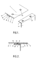
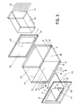
- First and second walls 1 and 3 are connected together via co-operating first and second edge regions 5 and 7, as shown in Figures 1 and 2.
- a narrow slot 19 is disposed along the inside face of the first wall 1 with its opening towards the edge of the wall.
- the slot is spaced from the edge of the wall and is formed by folding the portion of the wall along the edge rearwardly through a first return bend 9 so that a first part 11 of the first edge region is formed against the inner face 13 of the wall 1 including an elongate wall of the slot and then folding forwardly through a second return bend 15 so that a second part 17 of the first edge region including an opposite elongate wall of the slot 19, lies alongside the first part 11 thereof but spaced therefrom.
- the slot 19 is intended to receive the second edge region 7 of the second wall 3, which is at right angles to the plane of that side wall; the slot 19 is just wide enough to admit the second edge region 7 and provide a snug fit.
- coupling means in the form of spring lugs 21 which have been formed by pressing or stamping the second edge region 7 so that the lugs extend outwardly from the second edge region 7 and are inclined to the edge region 7 away from the edge thereof. Apertures in the first part 11 of the first edge region 5 are also formed by pressing or stamping. The lugs spring into these apertures during movement of the second edge region 7 into the slot 19 and are retained therein. In this way the edge regions 5 and 7 are mutually secured.
- edge regions of a casing may be fastened to one another or to an extra door or wall panel by a joint as just described.
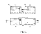
- Slot 19 and apertures 23 may be provided along the interior surface around a rectangular opening in a preformed main casing body of rectangular cross-section as shown in Figure 3.
- Lugs 21 can be formed along all the four edge regions of a side wall to be fitted to the opening. The side wall edge regions 7 can then be pushed into the slots 19 around the opening and the lugs 21 can then be engaged in the apertures 23 to provide secure engagement of the wall 3 to the main casing body.
- slots 19 could be formed on the exterior of the walls of the casing rather than on the inside thereof: in that case the lugs 21 would be pressed inwardly of the plane of the second edge regions 7 in order to engage the aperture 23 in the first parts 11 of the first edge regions 5.
- the lugs 21 could be made to engage apertures in the second part 17 of the edge regions though such arrangement would notbe aesthetically as attractive as that described above, especially if the slots are disposed on the outside rather than the inside of the casing.
- the interior of the casing shown in Figure 3 provides a microwave oven cavity 25.
- the casing comprising a main body 27 of rectangular cross-section which consists of parallel, spaced-apart, top and bottom walls 29,31, joined by a pair of parallel, spaced-apart side walls 33 and 35 (upright in use). The two remaining sides are open and a metal sheet wall 37, 39 is fitted onto each of these sides.
- These added walls 37,39 are attached to the open sides of the main body by means of the joint already described above and form the front and rear of the microwave oven in use.
- Slots 5 are disposed around each opening along the inside surface of the edge region of the wall of the body 27.
- the two added walls each have a second edge region 7 along their periphery; along the second edge region is disposed a row of regularly-spaced spring lugs 21.
- Each lug each engages in one of a row of corresponding apertures 23 (shown in broken lines) in the first part 11 of the corresponding first edge region 5.
- the main body 27 is made by bending a single sheet of metal into the shape of the four walls 29,31,33, and 35.
- the two walls having a free edge are secured together by a joint according to the invention.
- these are the bottom wall 31 and one of the side walls 35.
- the inside surface of the side wall 35 has a first edge region 5 with a groove 19, in one elongate wall of which a row of apertures 23 is formed.
- the edge region of the side wall co-operates with an opposed edge region 7 on the bottom wall 31, which has a row of spring lugs 21 which lock into the apertures 23 of the corresponding edge regions of the side wall.
- the front wall 37 includes an aperture 41 for access to the microwave oven cavity; the aperture is closed by a door (not shown) mounted in the edge region 5 around the front edge of side wall 33 as hereinafter described.
- the rear wall 39 includes a rectangular aperture 43.
- a regtangular electrical components chamber 45 is located in the micrwave oven cavity. The components chamber is fitted by being passed through the aperture 43 and secured to the front wall 41 by screws.
- the rear wall 39 of the components chamber has lateral flanges 47 secured by screws to rear wall 39.
- the electrical components chamber 45 is spaced from the top, bottom and side walls of the main body of the casing to allow for microwave energy circulation around the exterior of the chamber 45.
- a magnetron 49 is disposed in the components chamber 45.
- the chamber 45 can readily withdrawn from the oven cavity through the aperture 43 in the rear wall to factilitate servicing of the electrical components.
- the electrical components chamber 45 is provided with a louvred rear wall 51 which allows ventilation of the electrical components.
- the front wall 37 of the casing has internal lugs 55 for locating the chamber 45 in place prior to securing it to the wall 37 by screws which are passed through holes 53 in the front wall 37 to engage the adjoining wall of the chamber. Further holes 57 in the front wall of the casing are provided for mounting of door locking means.
- the casing includes a door hinge 61 by which a door can be mounted and as shown in Figure 4 comprises a pair of mutually-pivotally-mounted hinge plates 63 and 65.
- One plate 63 is secured along a vertical edge of the oven door whilst the other plate 64 is seated in the slot 19 of the first edge region 5 on the adjacent side wall 35 in which the second edge region 7 of the front wall 37 is also seated.
- the lugs 21 on the second edge region 7 of the front wall engage in apertures 23 of the second part 17 of the first edge region 5 of the side wall whilst the lugs 21 on the plate 65 engage in apertures 23 in the first part 11 of the first edge region 5.
- the door can be flush or recessed or proud of the front wall.
- the casing of this invention may be employed as a casing for ovens other than a microwave oven, for example an electric or gas oven, or for other household appliances having a metallic casing such as refrigerators, freezers, washing machines and tumble driers.
- the joint of the invention has been found to be highly secure.
Landscapes
- Physics & Mathematics (AREA)
- Electromagnetism (AREA)
- Electric Ovens (AREA)
- Casings For Electric Apparatus (AREA)
Applications Claiming Priority (2)
| Application Number | Priority Date | Filing Date | Title |
|---|---|---|---|
| GB8616062 | 1986-07-01 | ||
| GB868616062A GB8616062D0 (en) | 1986-07-01 | 1986-07-01 | Container |
Publications (1)
| Publication Number | Publication Date |
|---|---|
| EP0251782A1 true EP0251782A1 (de) | 1988-01-07 |
Family
ID=10600383
Family Applications (1)
| Application Number | Title | Priority Date | Filing Date |
|---|---|---|---|
| EP87305830A Withdrawn EP0251782A1 (de) | 1986-07-01 | 1987-07-01 | Verbindungen für Gehäuse von Haushaltsgeräten und solche Gehäuse |
Country Status (3)
| Country | Link |
|---|---|
| EP (1) | EP0251782A1 (de) |
| JP (1) | JPS63170997A (de) |
| GB (1) | GB8616062D0 (de) |
Cited By (6)
| Publication number | Priority date | Publication date | Assignee | Title |
|---|---|---|---|---|
| EP0884538A3 (de) * | 1997-06-12 | 1999-01-13 | Samsung Electronics Co., Ltd. | Gehäuse mit Tür |
| EP0949849A3 (de) * | 1998-04-08 | 2000-05-03 | Samsung Electronics Co., Ltd. | Mikrowellenherd versehen mit einem zurückziehbaren Innenraum |
| EP2053327A1 (de) | 2007-10-26 | 2009-04-29 | Liebherr-Hausgeräte Lienz GmbH | Haushaltgerät |
| EP2116800A1 (de) * | 2008-05-09 | 2009-11-11 | BSH Bosch und Siemens Hausgeräte GmbH | Kältegerät und zugehöriges Montageelement für dessen Deckplatte |
| WO2017097209A1 (zh) * | 2015-12-07 | 2017-06-15 | 广东美的厨房电器制造有限公司 | 烤箱 |
| CN112623548A (zh) * | 2020-12-30 | 2021-04-09 | 上海赢易环保科技有限公司 | 一种智能垃圾桶的吸袋装置及智能垃圾桶 |
Citations (7)
| Publication number | Priority date | Publication date | Assignee | Title |
|---|---|---|---|---|
| US3294276A (en) * | 1964-01-17 | 1966-12-27 | Bartaco Ind Ltd | Structural members and cabinets utilizing such members |
| US4192431A (en) * | 1977-10-25 | 1980-03-11 | General Motors Corporation | Microwave oven single wall construction |
| GB2052729A (en) * | 1979-06-22 | 1981-01-28 | British Gas Corp | Mounting assembly for gas appliance |
| GB2107160A (en) * | 1981-06-16 | 1983-04-20 | Sharp Kk | Microwave ovens |
| GB2161049A (en) * | 1984-06-15 | 1986-01-02 | Sharp Kk | Microwave oven structure |
| US4563559A (en) * | 1982-12-27 | 1986-01-07 | Enami Seiki Mfg. Co., Ltd. | Inner box for a cooking appliance |
| WO1986002143A1 (en) * | 1984-10-02 | 1986-04-10 | Matsushita Electric Industrial Co. Ltd. | High-frequency heater |
-
1986
- 1986-07-01 GB GB868616062A patent/GB8616062D0/en active Pending
-
1987
- 1987-07-01 EP EP87305830A patent/EP0251782A1/de not_active Withdrawn
- 1987-07-01 JP JP16251887A patent/JPS63170997A/ja active Pending
Patent Citations (7)
| Publication number | Priority date | Publication date | Assignee | Title |
|---|---|---|---|---|
| US3294276A (en) * | 1964-01-17 | 1966-12-27 | Bartaco Ind Ltd | Structural members and cabinets utilizing such members |
| US4192431A (en) * | 1977-10-25 | 1980-03-11 | General Motors Corporation | Microwave oven single wall construction |
| GB2052729A (en) * | 1979-06-22 | 1981-01-28 | British Gas Corp | Mounting assembly for gas appliance |
| GB2107160A (en) * | 1981-06-16 | 1983-04-20 | Sharp Kk | Microwave ovens |
| US4563559A (en) * | 1982-12-27 | 1986-01-07 | Enami Seiki Mfg. Co., Ltd. | Inner box for a cooking appliance |
| GB2161049A (en) * | 1984-06-15 | 1986-01-02 | Sharp Kk | Microwave oven structure |
| WO1986002143A1 (en) * | 1984-10-02 | 1986-04-10 | Matsushita Electric Industrial Co. Ltd. | High-frequency heater |
Non-Patent Citations (1)
| Title |
|---|
| PATENT ABSTRACTS OF JAPAN, vol. 9, no. 22 (M-354)[1745], 30th January 1985; & JP-A-59 167 638 (ENAMI SEIKI K.K.) 21-09-1984 * |
Cited By (7)
| Publication number | Priority date | Publication date | Assignee | Title |
|---|---|---|---|---|
| EP0884538A3 (de) * | 1997-06-12 | 1999-01-13 | Samsung Electronics Co., Ltd. | Gehäuse mit Tür |
| EP0949849A3 (de) * | 1998-04-08 | 2000-05-03 | Samsung Electronics Co., Ltd. | Mikrowellenherd versehen mit einem zurückziehbaren Innenraum |
| EP2053327A1 (de) | 2007-10-26 | 2009-04-29 | Liebherr-Hausgeräte Lienz GmbH | Haushaltgerät |
| EP2116800A1 (de) * | 2008-05-09 | 2009-11-11 | BSH Bosch und Siemens Hausgeräte GmbH | Kältegerät und zugehöriges Montageelement für dessen Deckplatte |
| WO2017097209A1 (zh) * | 2015-12-07 | 2017-06-15 | 广东美的厨房电器制造有限公司 | 烤箱 |
| CN112623548A (zh) * | 2020-12-30 | 2021-04-09 | 上海赢易环保科技有限公司 | 一种智能垃圾桶的吸袋装置及智能垃圾桶 |
| CN112623548B (zh) * | 2020-12-30 | 2022-07-01 | 上海赢易环保科技有限公司 | 一种智能垃圾桶的吸袋装置及智能垃圾桶 |
Also Published As
| Publication number | Publication date |
|---|---|
| JPS63170997A (ja) | 1988-07-14 |
| GB8616062D0 (en) | 1986-08-06 |
Similar Documents
| Publication | Publication Date | Title |
|---|---|---|
| US5568712A (en) | Refrigerator door construction | |
| JPH01117610A (ja) | 配電盤キャビネット | |
| US4788395A (en) | Configuration for joining components of a microwave oven | |
| CA1256510A (en) | Cavity construction for microwave oven | |
| US4282416A (en) | Unitized structure for a microwave oven | |
| JPS63170997A (ja) | 家庭用器具用ケ−スのためのジョイントとケ−ス | |
| US5818017A (en) | Microwave oven main body structure | |
| JPS5850172Y2 (ja) | 調理器 | |
| GB2355070A (en) | Cooking appliance chassis | |
| EP0893654B1 (de) | Ofentüre und Verfahren zu deren Zusammenbau | |
| CN215777255U (zh) | 壳体组件和烹饪器具 | |
| KR100398485B1 (ko) | 전자렌지의 도어 | |
| CN110242170A (zh) | 用于家用电器的门以及家用电器 | |
| KR200337672Y1 (ko) | 전자레인지 스테인리스카바의 고정구조 | |
| JP7833688B2 (ja) | 貯蔵庫 | |
| JPH09303793A (ja) | 組込式厨房家具 | |
| CN110243131A (zh) | 用于家用电器的门以及家用电器 | |
| JP3179993B2 (ja) | 加熱調理器 | |
| US20060151483A1 (en) | Oven | |
| KR860002502Y1 (ko) | 마이크로 웨이브 오븐 구조 | |
| KR200238113Y1 (ko) | 전자레인지의커넥터조립구조 | |
| KR200262395Y1 (ko) | 전자렌지 | |
| KR200378446Y1 (ko) | 전자레인지의프론트브라켓장착구조 | |
| KR20050036442A (ko) | 전자레인지의 베이스 플레이트 구조 | |
| KR0140619Y1 (ko) | 전자렌지의 도어 형합구조 |
Legal Events
| Date | Code | Title | Description |
|---|---|---|---|
| PUAI | Public reference made under article 153(3) epc to a published international application that has entered the european phase |
Free format text: ORIGINAL CODE: 0009012 |
|
| AK | Designated contracting states |
Kind code of ref document: A1 Designated state(s): AT BE CH DE ES FR GB GR IT LI LU NL SE |
|
| 17P | Request for examination filed |
Effective date: 19880317 |
|
| STAA | Information on the status of an ep patent application or granted ep patent |
Free format text: STATUS: THE APPLICATION HAS BEEN WITHDRAWN |
|
| 18W | Application withdrawn |
Withdrawal date: 19881208 |
|
| RIN1 | Information on inventor provided before grant (corrected) |
Inventor name: BEESLEY, PHILIP GRAHAM |