EP0252111B1 - Metre filiforme - Google Patents
Metre filiforme Download PDFInfo
- Publication number
- EP0252111B1 EP0252111B1 EP87900315A EP87900315A EP0252111B1 EP 0252111 B1 EP0252111 B1 EP 0252111B1 EP 87900315 A EP87900315 A EP 87900315A EP 87900315 A EP87900315 A EP 87900315A EP 0252111 B1 EP0252111 B1 EP 0252111B1
- Authority
- EP
- European Patent Office
- Prior art keywords
- thread
- casing
- guide
- measuring wheel
- meter
- Prior art date
- Legal status (The legal status is an assumption and is not a legal conclusion. Google has not performed a legal analysis and makes no representation as to the accuracy of the status listed.)
- Expired
Links
- NIXOWILDQLNWCW-UHFFFAOYSA-M Acrylate Chemical compound [O-]C(=O)C=C NIXOWILDQLNWCW-UHFFFAOYSA-M 0.000 description 1
- 239000004677 Nylon Substances 0.000 description 1
- 229920000122 acrylonitrile butadiene styrene Polymers 0.000 description 1
- 230000015572 biosynthetic process Effects 0.000 description 1
- 238000010276 construction Methods 0.000 description 1
- 239000013013 elastic material Substances 0.000 description 1
- 239000003365 glass fiber Substances 0.000 description 1
- 229920001778 nylon Polymers 0.000 description 1
- 229920003023 plastic Polymers 0.000 description 1
- 239000004033 plastic Substances 0.000 description 1
- 238000009958 sewing Methods 0.000 description 1
Images
Classifications
-
- G—PHYSICS
- G01—MEASURING; TESTING
- G01B—MEASURING LENGTH, THICKNESS OR SIMILAR LINEAR DIMENSIONS; MEASURING ANGLES; MEASURING AREAS; MEASURING IRREGULARITIES OF SURFACES OR CONTOURS
- G01B5/00—Measuring arrangements characterised by the use of mechanical techniques
- G01B5/02—Measuring arrangements characterised by the use of mechanical techniques for measuring length, width or thickness
- G01B5/04—Measuring arrangements characterised by the use of mechanical techniques for measuring length, width or thickness specially adapted for measuring length or width of objects while moving
- G01B5/043—Measuring arrangements characterised by the use of mechanical techniques for measuring length, width or thickness specially adapted for measuring length or width of objects while moving for measuring length
-
- B—PERFORMING OPERATIONS; TRANSPORTING
- B65—CONVEYING; PACKING; STORING; HANDLING THIN OR FILAMENTARY MATERIAL
- B65H—HANDLING THIN OR FILAMENTARY MATERIAL, e.g. SHEETS, WEBS, CABLES
- B65H61/00—Applications of devices for metering predetermined lengths of running material
-
- B—PERFORMING OPERATIONS; TRANSPORTING
- B65—CONVEYING; PACKING; STORING; HANDLING THIN OR FILAMENTARY MATERIAL
- B65H—HANDLING THIN OR FILAMENTARY MATERIAL, e.g. SHEETS, WEBS, CABLES
- B65H2701/00—Handled material; Storage means
- B65H2701/30—Handled filamentary material
- B65H2701/31—Textiles threads or artificial strands of filaments
Definitions
- This invention relates to a so-called thread meter, which is a device, out of which a thread can be drawn by moving the device away from a place where the free end of the thread is attached. At its outfeed, the thread is caused to actuate a counter, which records the length of thread fed out.
- Such thread meters are per se previously known.
- the known thread meters are arranged so that the thread prior to its leaving the device is passed and fed through several holes.
- One of them is, that it is very difficult in a hard environment, such as in a forest in wintertime or generally under bad weather conditions, to thread a thread, which is of the type sewing thread, through a plurality of small holes. This, however, is required when a thread reel is to be changed.
- the other disadvantage is, that the maximum feeding speed is extremely limited to prevent the thread from breaking.
- Such thread meters are used in many different connections when a distance is to be measured.
- the measuring of distances at forest surveys measuring of distances for military purposes such as for positioning artillery pieces, measuring of distances at construction work, land surveying, measuring of cable lengths required at power cable drawing etc., as well as in entirely different connections, such as measuring the length of an orienteering course etc.
- the present invention solves the aforesaid problems and provides a thread meter with a structure, which is much simpler and cheaper than at known thread meters.
- the present invention thus, relates to a thread meter comprising a holder for a thread reel, a counter provided with a rotary measuring wheel and guides for a thread, and an outer casing enclosing said details, and is characterized, in that a first guide for a thread is located between said holder and said measuring wheel, that a second guide for the thread is formed by means of said casing, which casing consists of a first and a second portion hingedly interconnected, where in said first portion a recess extends from an edge of the wall of the first portion, and where the second portion of the casing is arranged to bridge the opening of the recess along said edge, so that a hole with closed periphery is formed, and that said wheel is located along a line extending between said guides.
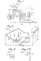
- Figs. 1 and 2 show a mechanism relating to the present thread meter and, respectively, a casing, where for the formation of a thread meter according to the invention the mechanism is placed in the casing
- Fig. 3 shows a portion of a third guide in detail
- Fig. 4 shows a first guide in detail.
- a thread meter according to the invention is shown.
- the numeral 1 designates a mechanism
- the numeral 2 designates a casing. It is only for the sake of clearness, that the thread meter is shown divided in two Figures.
- the mechanism 1 is so located in the casing 2, that the bottom plate 3 of the mechanism abuts the bottom 5 of the first portion 4 of the casing 2.
- the casing 2 also comprises a second portion 6, which constitutes a cover, which via hinges 7, 8 is hingedly connected with the first portion 4. Upon folding upward the second portion 6, as indicated by the arrow 9, the second portion 6 joins with the first portion 4, so that a parallelepiped box is formed, which entirely encloses the mechanism 1.
- Suitable snap-in devices 10, 11 are provided on the second portion 6 for co-operation with the upper lateral edge 12 of the first portion 4, so that the box can be kept closed.
- the mechanism 1 comprises a holder 13 for a thread reel, consisting of an upright pipe.
- a thread reel 14 is indicated by dashed lines.
- the mechanism further comprises a suitable known counter 15 provided with a rotary measuring wheel 16, about which a thread 20 is wound in one or several turns.
- the counter 15 records the number of turns, through which the measuring wheel 16 rotates, which corresponds to a certain distance, which can be read in the digit window 17 of the counter.
- the counter is provided with a zero setting button 18.
- a first guide 19 for the thread 20 is located between the holder 13 and measuring wheel 16.
- the guide 19 is connected with the bottom plate 3 and abuts with a certain pressure the measuring wheel via a cushion 21 of an elastic material. Between the cushion 21 and bottom plate 3, the guide is provided with a groove 22, which on one side is defined by two lugs 23, 24 bent away from each other. In Fig. 4 said guide is shown seen from the right in Fig. 1. This design implies, that a thread 20 can be inserted into the groove from the side, as indicated by the arrow 25 in Fig. 4.
- a second guide is formed by a recess 26 extending from one edge 27 of the wall of the first portion 4 of the casing, and by the second portion of the casing being arranged so that, when it is moved to its position joining the first portion, it bridges the opening 28 of the recess 26 along said edge 27, so that a hole with a closed periphery is formed.
- dash-dotted lines 29, 30 show the position for the edges 29', 30' of the second portion 6 of the casing when this portion is in said joining position.
- a third guide 31 is provided, which is shown partially also in Fig. 3, where the guide 31 is shown seen from the left in Fig. 1.
- the third guide 31 comprises a U-shaped groove 32 and spaced therefrom a shoulder 33, the lower edge 34 of which is located on a lower level than the opening of the U-shaped groove 32.
- This guide thus, also is formed so that a free opening 35 is provided where a thread can be directed into the groove 32.
- the third guide is located between the measuring wheel 16 and the second guide 26 and, when the mechanism is located in the casing 2, is located immediately inside of said recess 26.
- the thread must not be threaded through any hole, but can first be drawn out outside the device and thereafter be moved in a direction substantially perpendicular to the longitudinal direction of the thread so as to be located in the grooves 22, 32 and recess 26.
- a hole as stated, with closed periphery is formed through the wall of the casing by means of the recess 26 and edge 30'.
- This design implies, that it is very easy to position a thread even under hard weather conditions. It is further easy to joint a thread for a new thread reel. This is carried out so, that the thread from a substantially spent thread reel is drawn or out off outside the thread meter and thereafter tied to the leading end of the thread on a new thread reel, whereafter the used thread reel is removed and the new thread reel positioned on the holder 13.
- the function of said cushion 21 is to constitute a weak brake against the measuring wheel to prevent it from rotating when the person carrying the thread meter halts, and to see to it that the thread 20 abuts the measuring wheel 16.
- the measuring wheel 16 is located along a line extending between said first and second guides. According to a preferred embodiment, the measuring wheel 16 is located so that a line extending through said guides tangents the measuring wheel.
- the thread runs substantially along a straight line from the thread reel and out of the casing. This implies, that the thread meter can be moved at substantially higher speeds than known thread meters.
- the present thread meter thus, can be moved at speeds up to 40 km/hour without any problems whatsoever.
- the frame 36 of the mechanism is made in one piece, for example, of acrylate plastic.
- the measuring wheel 16 is made, for example, of nylon reinforced with glass fibres.
- the casing is made, for example, of ABS-plastic.
- the present thread meter thus, has a simple structure, allows for simple handling of the thread and has high performance.
Landscapes
- Physics & Mathematics (AREA)
- General Physics & Mathematics (AREA)
- Tape Measures (AREA)
- Storage Of Web-Like Or Filamentary Materials (AREA)
- A Measuring Device Byusing Mechanical Method (AREA)
Abstract
Claims (4)
Priority Applications (1)
| Application Number | Priority Date | Filing Date | Title |
|---|---|---|---|
| AT87900315T ATE48188T1 (de) | 1985-12-16 | 1986-12-09 | Drahtmessanordnung. |
Applications Claiming Priority (2)
| Application Number | Priority Date | Filing Date | Title |
|---|---|---|---|
| SE8505944 | 1985-12-16 | ||
| SE8505944A SE451095B (sv) | 1985-12-16 | 1985-12-16 | Tradmetare |
Publications (2)
| Publication Number | Publication Date |
|---|---|
| EP0252111A1 EP0252111A1 (fr) | 1988-01-13 |
| EP0252111B1 true EP0252111B1 (fr) | 1989-11-23 |
Family
ID=20362485
Family Applications (1)
| Application Number | Title | Priority Date | Filing Date |
|---|---|---|---|
| EP87900315A Expired EP0252111B1 (fr) | 1985-12-16 | 1986-12-09 | Metre filiforme |
Country Status (5)
| Country | Link |
|---|---|
| US (1) | US4798003A (fr) |
| EP (1) | EP0252111B1 (fr) |
| DE (1) | DE3667100D1 (fr) |
| SE (1) | SE451095B (fr) |
| WO (1) | WO1987003675A1 (fr) |
Families Citing this family (8)
| Publication number | Priority date | Publication date | Assignee | Title |
|---|---|---|---|---|
| US5065527A (en) * | 1990-03-15 | 1991-11-19 | Shaw Howard C | Length measuring and positive drive apparatus |
| GB9103673D0 (en) * | 1991-02-21 | 1991-04-10 | Benest Roger S | Measuring apparatus |
| US5267401A (en) * | 1992-07-24 | 1993-12-07 | Summagraphics Corporation | Method and apparatus for gauging reel diameters in a reel-to-reel sheet material transport system |
| US7007399B2 (en) * | 2003-08-22 | 2006-03-07 | Philip Joseph Catalano | Conduit measuring tool—device for measuring the length of electrical conduit |
| US7458170B1 (en) | 2006-02-17 | 2008-12-02 | Richardson Shane D | Automatic cord length measuring device |
| US20150192400A1 (en) * | 2014-01-03 | 2015-07-09 | Robert Joseph Rado | Handheld Measuring Device |
| CN110182679B (zh) * | 2018-02-23 | 2022-04-26 | 奥的斯电梯公司 | 速度监测装置及乘客运输装置 |
| US11279590B2 (en) * | 2020-01-27 | 2022-03-22 | United States Of America As Represented By The Secretary Of The Navy | Non-contact measurement of material remaining in expendable spools |
Family Cites Families (7)
| Publication number | Priority date | Publication date | Assignee | Title |
|---|---|---|---|---|
| US1448931A (en) * | 1920-03-09 | 1923-03-20 | Warren H Manning | Surveying instrument |
| US2706336A (en) * | 1950-10-10 | 1955-04-19 | Jack Hungerle | Measuring device for linear measurements |
| US2676411A (en) * | 1953-01-23 | 1954-04-27 | George F Horch | Topography measuring device |
| US2747286A (en) * | 1954-09-24 | 1956-05-29 | Berkley W Bedell | Line measuring device |
| US3253337A (en) * | 1963-10-30 | 1966-05-31 | Edward A Ebert | Line depth indicating device |
| US3763567A (en) * | 1972-03-30 | 1973-10-09 | Rexnord Inc | Stringline holder |
| SE441705C (sv) * | 1984-03-09 | 1987-11-09 | Hsb S Riksforbund Ek For | Anleggning for uppmetning av en volyms form och dimensioner |
-
1985
- 1985-12-16 SE SE8505944A patent/SE451095B/sv not_active IP Right Cessation
-
1986
- 1986-12-09 EP EP87900315A patent/EP0252111B1/fr not_active Expired
- 1986-12-09 US US07/087,679 patent/US4798003A/en not_active Expired - Lifetime
- 1986-12-09 WO PCT/SE1986/000560 patent/WO1987003675A1/fr not_active Ceased
- 1986-12-09 DE DE8787900315T patent/DE3667100D1/de not_active Expired
Also Published As
| Publication number | Publication date |
|---|---|
| DE3667100D1 (en) | 1989-12-28 |
| WO1987003675A1 (fr) | 1987-06-18 |
| SE8505944L (sv) | 1987-06-17 |
| EP0252111A1 (fr) | 1988-01-13 |
| SE451095B (sv) | 1987-08-31 |
| US4798003A (en) | 1989-01-17 |
| SE8505944D0 (sv) | 1985-12-16 |
Similar Documents
| Publication | Publication Date | Title |
|---|---|---|
| EP0252111B1 (fr) | Metre filiforme | |
| WO2002065425A1 (fr) | Systeme de surveillance du trafic routier | |
| FR2353661A1 (fr) | Metier a filer a fibres liberees (a bout ouvert) avec un dispositif d'echange de bobines pleines contre des tubes vides | |
| FR2486689B1 (fr) | Dispositif de rechargement a distance pour machine a affranchir | |
| KR860009283A (ko) | 오물배출 슬롯을 가진 코일식 줄자 하우징 | |
| DE2962044D1 (en) | Portable cassette for securities | |
| CN1043823C (zh) | 远距离读表装置 | |
| US4768290A (en) | Portable distance measuring device with pull out measuring filament | |
| US4438391A (en) | Electrical survey apparatus and method with spinner-type conductor supply | |
| US5089771A (en) | Reading device for a watt-hour meter | |
| KR940004879B1 (ko) | 에너지 소비량 측정 계기용 광전자 센서 조립체 | |
| DE69202358T2 (de) | Vorrichtung zur Abdichtung und Wartung mit verbesserter Leistung. | |
| FR2561864B1 (fr) | Machine d'irrigation a enrouleur muni d'un dispositif de traction | |
| KR960706676A (ko) | 테이프 카세트(Tape cassette) | |
| ES282232Y (es) | Cartucho de cinta magnetica | |
| CN111056387B (zh) | 安装柜 | |
| CA1258968A (fr) | Dispositif de mesurage au fil | |
| JPS58171905U (ja) | 敷きならし機械におけるピボツト位置表示装置 | |
| SU1607037A1 (ru) | Устройство дл измерени длины перематываемого кабел | |
| SU712643A1 (ru) | Рулетка дл измерени больших длин | |
| JPH0571725U (ja) | 置針式水位計 | |
| SU1370429A1 (ru) | Устройство дл поверки рулеток | |
| SU564509A1 (ru) | Рулетка дл измерени рассто ни | |
| ATE27506T1 (de) | Muenzspeicheranordnung. | |
| FR2615803B1 (fr) | Dispositif pour loger un parapluie a l'interieur d'un vehicule |
Legal Events
| Date | Code | Title | Description |
|---|---|---|---|
| PUAI | Public reference made under article 153(3) epc to a published international application that has entered the european phase |
Free format text: ORIGINAL CODE: 0009012 |
|
| AK | Designated contracting states |
Kind code of ref document: A1 Designated state(s): AT BE CH DE FR GB IT LI LU NL |
|
| 17P | Request for examination filed |
Effective date: 19871130 |
|
| 17Q | First examination report despatched |
Effective date: 19890417 |
|
| GRAA | (expected) grant |
Free format text: ORIGINAL CODE: 0009210 |
|
| AK | Designated contracting states |
Kind code of ref document: B1 Designated state(s): AT BE CH DE FR GB IT LI LU NL |
|
| PG25 | Lapsed in a contracting state [announced via postgrant information from national office to epo] |
Ref country code: IT Free format text: LAPSE BECAUSE OF FAILURE TO SUBMIT A TRANSLATION OF THE DESCRIPTION OR TO PAY THE FEE WITHIN THE PRE;WARNING: LAPSES OF ITALIAN PATENTS WITH EFFECTIVE DATE BEFORE 2007 MAY HAVE OCCURRED AT ANY TIME BEFORE 2007. THE CORRECT EFFECTIVE DATE MAY BE DIFFERENT FROM THE ONE RECORDED.SCRIBED TIME-LIMIT Effective date: 19891123 Ref country code: BE Effective date: 19891123 Ref country code: AT Effective date: 19891123 Ref country code: NL Effective date: 19891123 |
|
| REF | Corresponds to: |
Ref document number: 48188 Country of ref document: AT Date of ref document: 19891215 Kind code of ref document: T |
|
| REF | Corresponds to: |
Ref document number: 3667100 Country of ref document: DE Date of ref document: 19891228 |
|
| PG25 | Lapsed in a contracting state [announced via postgrant information from national office to epo] |
Ref country code: LU Free format text: LAPSE BECAUSE OF NON-PAYMENT OF DUE FEES Effective date: 19891231 |
|
| ET | Fr: translation filed | ||
| NLV1 | Nl: lapsed or annulled due to failure to fulfill the requirements of art. 29p and 29m of the patents act | ||
| PLBE | No opposition filed within time limit |
Free format text: ORIGINAL CODE: 0009261 |
|
| STAA | Information on the status of an ep patent application or granted ep patent |
Free format text: STATUS: NO OPPOSITION FILED WITHIN TIME LIMIT |
|
| 26N | No opposition filed | ||
| REG | Reference to a national code |
Ref country code: GB Ref legal event code: IF02 |
|
| PGFP | Annual fee paid to national office [announced via postgrant information from national office to epo] |
Ref country code: CH Payment date: 20021212 Year of fee payment: 17 |
|
| PGFP | Annual fee paid to national office [announced via postgrant information from national office to epo] |
Ref country code: DE Payment date: 20021223 Year of fee payment: 17 |
|
| PGFP | Annual fee paid to national office [announced via postgrant information from national office to epo] |
Ref country code: GB Payment date: 20031121 Year of fee payment: 18 |
|
| PG25 | Lapsed in a contracting state [announced via postgrant information from national office to epo] |
Ref country code: CH Free format text: LAPSE BECAUSE OF NON-PAYMENT OF DUE FEES Effective date: 20031231 Ref country code: LI Free format text: LAPSE BECAUSE OF NON-PAYMENT OF DUE FEES Effective date: 20031231 |
|
| PG25 | Lapsed in a contracting state [announced via postgrant information from national office to epo] |
Ref country code: DE Free format text: LAPSE BECAUSE OF NON-PAYMENT OF DUE FEES Effective date: 20040701 |
|
| REG | Reference to a national code |
Ref country code: CH Ref legal event code: PL |
|
| PG25 | Lapsed in a contracting state [announced via postgrant information from national office to epo] |
Ref country code: GB Free format text: LAPSE BECAUSE OF NON-PAYMENT OF DUE FEES Effective date: 20041209 |
|
| GBPC | Gb: european patent ceased through non-payment of renewal fee |
Effective date: 20041209 |
|
| PGFP | Annual fee paid to national office [announced via postgrant information from national office to epo] |
Ref country code: FR Payment date: 20051130 Year of fee payment: 20 |