EP0252178A1 - Enveloppe pour moteur de propulsion dans les automobiles - Google Patents
Enveloppe pour moteur de propulsion dans les automobiles Download PDFInfo
- Publication number
- EP0252178A1 EP0252178A1 EP86109435A EP86109435A EP0252178A1 EP 0252178 A1 EP0252178 A1 EP 0252178A1 EP 86109435 A EP86109435 A EP 86109435A EP 86109435 A EP86109435 A EP 86109435A EP 0252178 A1 EP0252178 A1 EP 0252178A1
- Authority
- EP
- European Patent Office
- Prior art keywords
- capsule
- motor
- base body
- engine
- basic
- Prior art date
- Legal status (The legal status is an assumption and is not a legal conclusion. Google has not performed a legal analysis and makes no representation as to the accuracy of the status listed.)
- Granted
Links
Images





Classifications
-
- F—MECHANICAL ENGINEERING; LIGHTING; HEATING; WEAPONS; BLASTING
- F02—COMBUSTION ENGINES; HOT-GAS OR COMBUSTION-PRODUCT ENGINE PLANTS
- F02B—INTERNAL-COMBUSTION PISTON ENGINES; COMBUSTION ENGINES IN GENERAL
- F02B77/00—Component parts, details or accessories, not otherwise provided for
- F02B77/11—Thermal or acoustic insulation
- F02B77/13—Acoustic insulation
Definitions
- the invention relates to a device for soundproofing a drive motor in a motor vehicle, in particular a commercial vehicle, by means of a capsule enclosing it at a short distance.
- the cooling flow of a cooling fan is to be guided through the capsule.
- Such a passage of cooling air through a closed muffler capsule has the purpose of cooling the additional motor units arranged inside the muffler capsule in order to justify the temperature increase caused by the capsule or the engine's own heat development that cannot be dissipated in a justifiable manner Keep limits.
- a disadvantage of carrying the cooling air of a cooling fan through the capsule is that the cooling air inlet and outlet openings have to be made relatively large, in particular in the case of larger motors, and are therefore very difficult to protect against the escape of sound from the capsule.
- a very significant disadvantage of the capsule described in the publication is that the auxiliary units are difficult to access for maintenance and repair purposes, even if closable openings are provided.
- a device described at the outset for soundproofing motors is also known from DT-PS 3 06 982.
- this document does not deal with the problem of heat balance in the case of encapsulated motors and also gives no indication of how auxiliary units of the encapsulated motors can be protected against overheating.
- the invention has for its object to provide a generic sound damping device that has a high Dampfungsgsrad, which is designed to save space and weight, good accessibility to the drive motor and the associated units for maintenance and repair work and at the same time allows operating temperatures of the drive motor and to keep the other drive and auxiliary units low despite the noise damping device.
- the capsule is constructed in several parts and consists of a preferably cubic, self-supporting capsule base body, which forms an assembly unit with the base motor, and an upper cover and oil pan cladding which can be connected to the capsule base body after the engine test run , wherein the capsule base has openings for connecting the motor to its retrofittable ancillary units and for these at least partially and / or in some areas connection capsules or other noise-damping elements known per se are provided, which are either connected directly to the base motor or to the capsule base are. Since the capsule is arranged relatively close to the motor contour due to the exclusion of the auxiliary units, the sound attenuation begins immediately where the sound is generated, so that only a small area is illuminated by the main noise source.
- auxiliary units has the further considerable advantage that only a small amount of air is used, which is not defined as cooling air but as purge air. Such a correspondingly large cooling fan is omitted, the small amount of purge air is only used, for. B. to effectively counter an explosion hazard due to accumulation of gases.
- An essential advantage of the device according to the invention is that it is easy to maintain, repair and install; the capsule division optimally takes into account the band production by integrating the cubic, self-supporting capsule base body as an assembly part in the band production. The intervention options remain almost the same as for the unenclosed motor. By removing the Upper cover can be replaced: valve cover, cylinder heads, injector holder, screw connections of the injection lines, exhaust manifold and all corresponding seals.
- oil pan cover is also removed, the following can also be replaced: oil pan, pistons, connecting rods, cylinder liners, connecting rod bearings, crankshaft bearings and all corresponding seals and the like.
- the capsule body is associated with the engine and only needs if the crankcase is defective, e.g. B. by frost damage.
- the capsule is a self-supporting structure provided with openings for the auxiliary units and should therefore not be understood as a series of facing shells. Since the soundproofing of an internal combustion engine is a very complex process, the measures described above must be supplemented by further, mainly additional encapsulations and primary soundproofing.
- auxiliary units are arranged outside of the capsule body, the upper cover and the oil pan cladding: air compressor, alternator, hydraulic motor for power steering, exhaust gas turbocharger, manual transmission, V-belt and V-belt pulley of water pump, alternator and fan, torsion damper, tensioner pulley, water thermostat , Water pump, viscous coupling for fans, water hoses, hose connections, fuel feed pump, fuel filter and engine mounting.
- the entire capsule is only very slightly ventilated over absorption sections, the effect being caused by the air flowing out Radiator fan, e.g. B. by means of bypass and by air inside the capsule due to thermal amplification.
- the capsule is aerated with a small amount of purge air to avoid the accumulation of flammable gases. Cooling air is not required because the heat-generating accessories are outside the capsule and the engine itself is water-cooled.
- a partitioned space is provided around the exhaust manifold with corresponding supply and exhaust air openings, the partitioned space being provided by an additional capsule integrally associated with one half of the capsule body and the other half with the upper cover, and through a partition wall encompassing the exhaust manifold inlet is formed.
- the air heated at the exhaust manifold is directed upwards, so that cold air (approx. 330 K) can be drawn in from the capsule and the air movement inside the capsule is supported.
- a quasi "divided room” is formed around the exhaust manifold with corresponding supply and exhaust air openings.
- Cooling in the area mentioned also makes sense because partial overheating is avoided and the use of particularly expensive materials (seals and high-quality alloys for exhaust manifolds and screws) is eliminated. Coking of the engine oil on the inside of the valve covers and heating of the cylinder head are also avoided.
- these encompassing and shielding front shells are arranged on the oil filter head and on the charging group of the exhaust gas turbine.
- the above-described ancillary units whose airborne sound radiation is measurably involved in the overall noise level, are made by absorbing facing shells shielded.
- the storage of the facing shells is decoupled from structure-borne noise on the internal combustion engine or on the auxiliary unit itself.
- the absorbing facing shells do not need to lie close to the capsule, but can be arranged at a distance from the capsule and the aggregate, so that assembly and maintenance are not impaired.
- an additional damping against the noise resulting from axially similar vibrations is attached to a torsion damper consisting of a primary part and a rubber part, whereby both sides of the end faces of the torsion damper are provided, one of which directly and the other via Connection plates, which are arranged within the V-belt guide, are connected to the outer wall of the capsule base body.
- V-belt pulleys e.g. B. for water pump and alternator
- the V-belt pulleys consist of primary and secondary parts, which are connected to each other on the end face via several elastomer rings or the like and have a small annular space filled with viscose liquid on the inside.
- V-belt pulleys must either have much more mass or, as the invention shows, there must be structure-borne noise decoupling. Additional damping is achieved by introducing viscose liquid between the hub parts.
- the vibrating metals connecting the capsule base body to the base motor are arranged on the outside of the capsule base body. In this way, they are visible, measurable and interchangeable without having to disassemble the capsule. They are also advantageously not influenced by the temperature prevailing in the capsule, which increases their resistance to aging.
- the exhaust pipe is structure-borne soundproofed, an outer pipe being arranged at a distance from the inner exhaust pipe and the intermediate space being made with an elastic fabric, e.g. B. asbestos substitute or filled with air, or it is the exhaust pipe in a certain, depending on the radiated frequency spectrum surrounded by a pipe silencer.
- an elastic fabric e.g. B. asbestos substitute or filled with air
- the acoustic weak points here are the inner compensators, as well as reinforced hoses, even in heavy versions.
- the cavity between the motor and the capsule is filled with absorption material.
- the space between the capsule and the motor describes a diffuse reverberation space.
- Absorption material is installed to reduce the reverberation effect and thus increase the capsule effect.
- the points of absorption are not so significant.
- the percentage of the absorption area in the total area is more important. Damping pads are applied to strongly vibrating capsule surfaces beforehand.
- the invention is illustrated in a large number of exemplary embodiments.
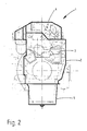
- FIG. 1 and 2 show an internal combustion engine (3) with a complete capsule (1), which consists of a capsule base body (2), an upper cover (4) and an oil pan lining (5).
- the individual capsule components are preferably connected to one another via commercially available quick fasteners.
- a serious feature of this capsule arrangement is that all of the auxiliary units that are not absolutely necessary for a test run are located outside the capsule and additional measures have been taken to reduce their noise component in the overall noise level. In this way there is no cooling of the heat-radiating auxiliary units which, if they were arranged in the capsule, would require a cooling air flow and thus an additional large-volume cooler. However, it is sufficient to branch off a very small amount of purge air from the radiator fan so that no flammable gases can form inside the capsule.
- Fig. 3 shows the connection of the capsule body (2) to the motor housing (8), namely by means of vibrating metal elements (6, 7), which are attached to the outside of the capsule, so that each one can be replaced without disassembling the capsule itself.
- Fig. 4 shows the encapsulation of the exhaust manifold (9) by means of a capsule part (11), which is assigned in one piece to the capsule base body (2) and the other half in one piece to the upper cover (4).
- a partition (12) By arranging a partition (12) on the engine-facing part of the exhaust manifold, enclosing the same, a partitioned space (10) is created, whereby the air heated at the exhaust manifold is directed upwards and cold air (approx. 330 K) is drawn in from the lower capsule area .
- the cutting disc (12) consists of a sheet with an insulating layer (14) and a steel sheet (13) attached to it, on which a further steel sheet (15) is arranged at a distance.
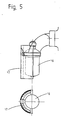
- Fig. 5 shows an oil filter head (16) with a spaced absorbent facing (17). This arrangement allows easy access to the oil filter at any time to perform maintenance or cleaning tasks on it.
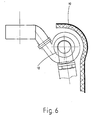
- Fig. 6 shows the charging group (18), (gas turbine + compressor) with a noise-absorbing front shell (19) arranged at a distance from it.
- Fig. 7 shows a torsion damper (23) and Fig. 8 shows the arrangement of this torsion damper in a front view.
- the primary part (20) of the torsion damper (23) attached to the crankshaft is connected via a rubber part (22) to a secondary part (21) containing the V-belt grooves.
- Front shells (24, 25) are arranged on the end face of the torsion damper (23), the front shell (24) being attached directly and the front shell (25) via connecting plates (26) on the outer wall of the capsule base body.
- the size of the facing shells corresponds to the diameter of the torsion damper (23).
- the connecting plates (26) lie within the V-belt guide (27) of the torsion damper (23), alternator V-belt pulley (28) and water pump V-belt pulley (29).
- the facing shells (24, 25) can also be firmly connected to the torsion damper (23).
- the V-belt pulleys (28, 29) consist of a primary part (30) and a secondary part (31). These are connected to one another at the end face via elastomer rings (32, 33). On the inside there is an annular space (33) between the parts (30) and (31), which is filled with viscose material.
- Figures 10 and 11 show structure-borne noise-insulated exhaust pipes (34).
- the exhaust pipes between the manifold and the muffler in conventional design already emit considerable airborne noise caused by structure-borne noise.
- an outer tube (35) is arranged at a distance from the exhaust pipe (34), the intermediate space (36) having an elastic intermediate layer (36) (e.g. asbestos substitute) or air is filled.
- the exhaust pipe (34) is surrounded by a silencer (37) which consists of a perforated plate (39), absorption material (40) and an outer pipe (41) arranged at a distance from it.
- Fig. 12 shows an intake pipe (42) with surface silencer (46).
- the suction line (42) is composed of a partial section (43) and a partial section (44) which are connected by an inner compensator (45).
- the internal compensator is completely sufficient for an unenclosed motor, but not for an encapsulated one.
- the external expansion joints (47, 48), which are arranged on the front and are connected to the silencer (46), are used here.
- the surface silencer (46) with external expansion joints (47, 48) is preferably used when a short overall length is required and / or very high pulsations and vibrations are present.
- Openings here not provided with reference numerals that are important for maintenance work, such as. B. oil filler neck, nozzle for oil level control and oil drain are led out of the capsule.
- the space between capsule (1) and motor (3) describes a diffuse reverberation space; To reduce the reverberation effect and thus increase the capsule effect, absorption material is installed.
- the points of absorption are not so significant, more important is the percentage of the absorption area of the total area, the thickness of the absorption material being limited by the space between the capsule and the motor.
- closable bores are provided at certain points on the capsule, by means of which holes can be measured at reference points on the motor.
- the reference points on the engine are specially machined surfaces.
Landscapes
- Engineering & Computer Science (AREA)
- Physics & Mathematics (AREA)
- Acoustics & Sound (AREA)
- Chemical & Material Sciences (AREA)
- Combustion & Propulsion (AREA)
- Mechanical Engineering (AREA)
- General Engineering & Computer Science (AREA)
- Exhaust Silencers (AREA)
- Lubrication Details And Ventilation Of Internal Combustion Engines (AREA)
- Compressors, Vaccum Pumps And Other Relevant Systems (AREA)
- Medicinal Preparation (AREA)
- Noise Elimination (AREA)
Priority Applications (4)
| Application Number | Priority Date | Filing Date | Title |
|---|---|---|---|
| EP86109435A EP0252178B2 (fr) | 1986-07-10 | 1986-07-10 | Enveloppe pour moteur de propulsion dans les automobiles |
| AT86109435T ATE50024T1 (de) | 1986-07-10 | 1986-07-10 | Kapsel fuer antriebsmotor in kraftfahrzeugen. |
| DE8686109435T DE3668664D1 (de) | 1986-07-10 | 1986-07-10 | Kapsel fuer antriebsmotor in kraftfahrzeugen. |
| JP62170836A JPS6325322A (ja) | 1986-07-10 | 1987-07-08 | 自動車の騒音低減装置 |
Applications Claiming Priority (1)
| Application Number | Priority Date | Filing Date | Title |
|---|---|---|---|
| EP86109435A EP0252178B2 (fr) | 1986-07-10 | 1986-07-10 | Enveloppe pour moteur de propulsion dans les automobiles |
Publications (3)
| Publication Number | Publication Date |
|---|---|
| EP0252178A1 true EP0252178A1 (fr) | 1988-01-13 |
| EP0252178B1 EP0252178B1 (fr) | 1990-01-31 |
| EP0252178B2 EP0252178B2 (fr) | 1993-06-09 |
Family
ID=8195261
Family Applications (1)
| Application Number | Title | Priority Date | Filing Date |
|---|---|---|---|
| EP86109435A Expired - Lifetime EP0252178B2 (fr) | 1986-07-10 | 1986-07-10 | Enveloppe pour moteur de propulsion dans les automobiles |
Country Status (4)
| Country | Link |
|---|---|
| EP (1) | EP0252178B2 (fr) |
| JP (1) | JPS6325322A (fr) |
| AT (1) | ATE50024T1 (fr) |
| DE (1) | DE3668664D1 (fr) |
Cited By (2)
| Publication number | Priority date | Publication date | Assignee | Title |
|---|---|---|---|---|
| DE3929592A1 (de) * | 1989-09-06 | 1991-03-28 | Man Nutzfahrzeuge Ag | Schallgedaemmte blech-oelwanne fuer brennkraftmaschinen |
| EP3382178A1 (fr) * | 2017-03-27 | 2018-10-03 | Toyota Jidosha Kabushiki Kaisha | Moteur à combustion interne |
Families Citing this family (1)
| Publication number | Priority date | Publication date | Assignee | Title |
|---|---|---|---|---|
| JP5615588B2 (ja) * | 2010-05-06 | 2014-10-29 | 日本車輌製造株式会社 | エンジン作業機 |
Citations (9)
| Publication number | Priority date | Publication date | Assignee | Title |
|---|---|---|---|---|
| GB145062A (en) * | 1915-12-18 | 1920-12-09 | Daimler Motoren | Improvements in and connected with means for preventing the transmission of sound and vibration from machines and parts thereof |
| US3412724A (en) * | 1966-01-10 | 1968-11-26 | List Hans | Soundproofed internal combustion engine |
| US3464398A (en) * | 1967-06-02 | 1969-09-02 | List Hans | Soundproofed internal combustion engine |
| US3684053A (en) * | 1970-09-02 | 1972-08-15 | List Hans | Internal combustion engine with sound-absorbing casing |
| US4137888A (en) * | 1976-11-24 | 1979-02-06 | Allis-Chalmers Corporation | Sound abatement device for internal combustion engine |
| GB2002850A (en) * | 1977-08-18 | 1979-02-28 | List H | Low-noise internal combustion engines |
| FR2407350A1 (fr) * | 1977-10-28 | 1979-05-25 | List Hans | Moteur a combustion interne avec blindage amortisseur du bruit |
| EP0062030A1 (fr) * | 1981-03-31 | 1982-10-06 | Steyr-Daimler-Puch Aktiengesellschaft | Moteur à combustion interne à piston alternatif |
| DE3225347A1 (de) * | 1981-07-14 | 1983-02-10 | List, Hans, Prof. Dipl.-Ing. Dr.Dr.h.c., 8020 Graz | Wassergekuehlte brennkraftmaschine |
-
1986
- 1986-07-10 AT AT86109435T patent/ATE50024T1/de not_active IP Right Cessation
- 1986-07-10 EP EP86109435A patent/EP0252178B2/fr not_active Expired - Lifetime
- 1986-07-10 DE DE8686109435T patent/DE3668664D1/de not_active Expired - Lifetime
-
1987
- 1987-07-08 JP JP62170836A patent/JPS6325322A/ja active Pending
Patent Citations (9)
| Publication number | Priority date | Publication date | Assignee | Title |
|---|---|---|---|---|
| GB145062A (en) * | 1915-12-18 | 1920-12-09 | Daimler Motoren | Improvements in and connected with means for preventing the transmission of sound and vibration from machines and parts thereof |
| US3412724A (en) * | 1966-01-10 | 1968-11-26 | List Hans | Soundproofed internal combustion engine |
| US3464398A (en) * | 1967-06-02 | 1969-09-02 | List Hans | Soundproofed internal combustion engine |
| US3684053A (en) * | 1970-09-02 | 1972-08-15 | List Hans | Internal combustion engine with sound-absorbing casing |
| US4137888A (en) * | 1976-11-24 | 1979-02-06 | Allis-Chalmers Corporation | Sound abatement device for internal combustion engine |
| GB2002850A (en) * | 1977-08-18 | 1979-02-28 | List H | Low-noise internal combustion engines |
| FR2407350A1 (fr) * | 1977-10-28 | 1979-05-25 | List Hans | Moteur a combustion interne avec blindage amortisseur du bruit |
| EP0062030A1 (fr) * | 1981-03-31 | 1982-10-06 | Steyr-Daimler-Puch Aktiengesellschaft | Moteur à combustion interne à piston alternatif |
| DE3225347A1 (de) * | 1981-07-14 | 1983-02-10 | List, Hans, Prof. Dipl.-Ing. Dr.Dr.h.c., 8020 Graz | Wassergekuehlte brennkraftmaschine |
Non-Patent Citations (2)
| Title |
|---|
| AUTOMOBILTECHNISCHE ZEITSCHRIFT, Band 74, Nr. 7, Juli 1972, Seiten 261-268, Stuttgart, DE; G.E. THIEN et al.: "Möglichkeiten zur Senkung des Geräuschpegels von Dieselmotoren" * |
| SAE JOURNAL, Band 78, Nr. 4, April 1970, Seiten 20-27, New York, US; T. PRIEDE et al.: "Cut engine noise three ways" * |
Cited By (2)
| Publication number | Priority date | Publication date | Assignee | Title |
|---|---|---|---|---|
| DE3929592A1 (de) * | 1989-09-06 | 1991-03-28 | Man Nutzfahrzeuge Ag | Schallgedaemmte blech-oelwanne fuer brennkraftmaschinen |
| EP3382178A1 (fr) * | 2017-03-27 | 2018-10-03 | Toyota Jidosha Kabushiki Kaisha | Moteur à combustion interne |
Also Published As
| Publication number | Publication date |
|---|---|
| JPS6325322A (ja) | 1988-02-02 |
| EP0252178B2 (fr) | 1993-06-09 |
| ATE50024T1 (de) | 1990-02-15 |
| EP0252178B1 (fr) | 1990-01-31 |
| DE3668664D1 (de) | 1990-03-08 |
Similar Documents
| Publication | Publication Date | Title |
|---|---|---|
| EP2027370B1 (fr) | Dispositif pour influencer l'écoulement de gaz d'échappement | |
| DE1576775C3 (de) | Brennkraftmaschine mit schallisolierender Verschalung | |
| US3412724A (en) | Soundproofed internal combustion engine | |
| DE3831334A1 (de) | Brennkraftmaschine mit schalldaempfender verschalung | |
| DE4214799A1 (de) | Dieselbrennkraftmaschine | |
| EP0252178B1 (fr) | Enveloppe pour moteur de propulsion dans les automobiles | |
| DE10309808B4 (de) | Kühlsystem für eine Brennkraftmaschine mit zweistufiger Aufladung | |
| EP2396552B1 (fr) | Amortisseur de bruit pour une turbomachine ou machine à piston | |
| DE2844269C2 (de) | Brennkraftmaschine mit schalldämmender Verschalung | |
| DE102013017276A1 (de) | Verbrennungskraftmaschine, insbesondere für einen Kraftwagen | |
| EP0062030B1 (fr) | Moteur à combustion interne à piston alternatif | |
| DE102010017933B4 (de) | Geräuschdämpfer für variable Frequenzen für rotierende Einrichtungen | |
| DE102010036303A1 (de) | Verbrennungsmotor mit liegend angeordneten Zylinderbänken und Abgasturbolader | |
| EP1079080B1 (fr) | Moteur à combustion interne refroidi par de l'huile | |
| DE102007053493A1 (de) | Wasserpumpenträger zum Anbau an einer Brennkraftmaschine | |
| DE10317691B4 (de) | Kühlanordnung für ein Getriebe vom Riementyp | |
| DE102007004419A1 (de) | Wasserpumpenträger zum Anbau an einer Brennkraftmaschine | |
| CH599458A5 (en) | Air cooled internal combustion engine | |
| DE2411490B2 (de) | Kraftfahrzeug, insbesondere Nutzfahrzeug | |
| DE69523315T2 (de) | Schalldämpfer mit katalytischem konverter | |
| DE2853525A1 (de) | Turbolader | |
| AT399916B (de) | Brennkraftmaschine mit schalldämmender verschalung | |
| DE2831879A1 (de) | Waermepumpenantrieb | |
| DE3240424C2 (fr) | ||
| AT276867B (de) | Brennkraftmaschine |
Legal Events
| Date | Code | Title | Description |
|---|---|---|---|
| PUAI | Public reference made under article 153(3) epc to a published international application that has entered the european phase |
Free format text: ORIGINAL CODE: 0009012 |
|
| AK | Designated contracting states |
Kind code of ref document: A1 Designated state(s): AT BE CH DE FR GB IT LI LU NL SE |
|
| 17P | Request for examination filed |
Effective date: 19880210 |
|
| 17Q | First examination report despatched |
Effective date: 19880519 |
|
| ITF | It: translation for a ep patent filed | ||
| RAP1 | Party data changed (applicant data changed or rights of an application transferred) |
Owner name: MAN NUTZFAHRZEUGE AKTIENGESELLSCHAFT |
|
| GRAA | (expected) grant |
Free format text: ORIGINAL CODE: 0009210 |
|
| AK | Designated contracting states |
Kind code of ref document: B1 Designated state(s): AT BE CH DE FR GB IT LI LU NL SE |
|
| PG25 | Lapsed in a contracting state [announced via postgrant information from national office to epo] |
Ref country code: GB Effective date: 19900131 |
|
| REF | Corresponds to: |
Ref document number: 50024 Country of ref document: AT Date of ref document: 19900215 Kind code of ref document: T |
|
| ET | Fr: translation filed | ||
| REF | Corresponds to: |
Ref document number: 3668664 Country of ref document: DE Date of ref document: 19900308 |
|
| GBT | Gb: translation of ep patent filed (gb section 77(6)(a)/1977) | ||
| PLBI | Opposition filed |
Free format text: ORIGINAL CODE: 0009260 |
|
| 26 | Opposition filed |
Opponent name: KLOECKNER-HUMBOLDT-DEUTZ AG Effective date: 19901027 |
|
| NLR1 | Nl: opposition has been filed with the epo |
Opponent name: KLOECKNER-HUMBOLDT-DEUTZ AG |
|
| ITTA | It: last paid annual fee | ||
| PGFP | Annual fee paid to national office [announced via postgrant information from national office to epo] |
Ref country code: CH Payment date: 19920529 Year of fee payment: 7 |
|
| PGFP | Annual fee paid to national office [announced via postgrant information from national office to epo] |
Ref country code: SE Payment date: 19920603 Year of fee payment: 7 |
|
| PGFP | Annual fee paid to national office [announced via postgrant information from national office to epo] |
Ref country code: AT Payment date: 19920609 Year of fee payment: 7 |
|
| PGFP | Annual fee paid to national office [announced via postgrant information from national office to epo] |
Ref country code: BE Payment date: 19920624 Year of fee payment: 7 |
|
| PGFP | Annual fee paid to national office [announced via postgrant information from national office to epo] |
Ref country code: GB Payment date: 19920626 Year of fee payment: 7 |
|
| PGFP | Annual fee paid to national office [announced via postgrant information from national office to epo] |
Ref country code: LU Payment date: 19920722 Year of fee payment: 7 |
|
| EPTA | Lu: last paid annual fee | ||
| PUAH | Patent maintained in amended form |
Free format text: ORIGINAL CODE: 0009272 |
|
| STAA | Information on the status of an ep patent application or granted ep patent |
Free format text: STATUS: PATENT MAINTAINED AS AMENDED |
|
| 27A | Patent maintained in amended form |
Effective date: 19930609 |
|
| AK | Designated contracting states |
Kind code of ref document: B2 Designated state(s): AT BE CH DE FR GB IT LI LU NL SE |
|
| REG | Reference to a national code |
Ref country code: CH Ref legal event code: AEN |
|
| ET3 | Fr: translation filed ** decision concerning opposition | ||
| PG25 | Lapsed in a contracting state [announced via postgrant information from national office to epo] |
Ref country code: LU Free format text: LAPSE BECAUSE OF NON-PAYMENT OF DUE FEES Effective date: 19930710 Ref country code: AT Effective date: 19930710 |
|
| PG25 | Lapsed in a contracting state [announced via postgrant information from national office to epo] |
Ref country code: SE Effective date: 19930711 |
|
| PG25 | Lapsed in a contracting state [announced via postgrant information from national office to epo] |
Ref country code: LI Effective date: 19930731 Ref country code: CH Effective date: 19930731 Ref country code: BE Free format text: LAPSE BECAUSE OF NON-PAYMENT OF DUE FEES Effective date: 19930731 |
|
| NLR2 | Nl: decision of opposition | ||
| NLR3 | Nl: receipt of modified translations in the netherlands language after an opposition procedure | ||
| GBV | Gb: ep patent (uk) treated as always having been void in accordance with gb section 77(7)/1977 [no translation filed] |
Effective date: 19900131 |
|
| REG | Reference to a national code |
Ref country code: CH Ref legal event code: PL |
|
| PGFP | Annual fee paid to national office [announced via postgrant information from national office to epo] |
Ref country code: NL Payment date: 19940731 Year of fee payment: 9 |
|
| EUG | Se: european patent has lapsed |
Ref document number: 86109435.7 Effective date: 19930914 |
|
| PG25 | Lapsed in a contracting state [announced via postgrant information from national office to epo] |
Ref country code: NL Effective date: 19960201 |
|
| NLV4 | Nl: lapsed or anulled due to non-payment of the annual fee |
Effective date: 19960201 |
|
| PGFP | Annual fee paid to national office [announced via postgrant information from national office to epo] |
Ref country code: FR Payment date: 19960621 Year of fee payment: 11 |
|
| PGFP | Annual fee paid to national office [announced via postgrant information from national office to epo] |
Ref country code: DE Payment date: 19960624 Year of fee payment: 11 |
|
| PG25 | Lapsed in a contracting state [announced via postgrant information from national office to epo] |
Ref country code: FR Free format text: LAPSE BECAUSE OF NON-PAYMENT OF DUE FEES Effective date: 19980331 |
|
| PG25 | Lapsed in a contracting state [announced via postgrant information from national office to epo] |
Ref country code: DE Free format text: LAPSE BECAUSE OF NON-PAYMENT OF DUE FEES Effective date: 19980401 |
|
| REG | Reference to a national code |
Ref country code: FR Ref legal event code: ST |
|
| PG25 | Lapsed in a contracting state [announced via postgrant information from national office to epo] |
Ref country code: IT Free format text: LAPSE BECAUSE OF NON-PAYMENT OF DUE FEES;WARNING: LAPSES OF ITALIAN PATENTS WITH EFFECTIVE DATE BEFORE 2007 MAY HAVE OCCURRED AT ANY TIME BEFORE 2007. THE CORRECT EFFECTIVE DATE MAY BE DIFFERENT FROM THE ONE RECORDED. Effective date: 20050710 |