EP0062030A1 - Moteur à combustion interne à piston alternatif - Google Patents
Moteur à combustion interne à piston alternatif Download PDFInfo
- Publication number
- EP0062030A1 EP0062030A1 EP82890045A EP82890045A EP0062030A1 EP 0062030 A1 EP0062030 A1 EP 0062030A1 EP 82890045 A EP82890045 A EP 82890045A EP 82890045 A EP82890045 A EP 82890045A EP 0062030 A1 EP0062030 A1 EP 0062030A1
- Authority
- EP
- European Patent Office
- Prior art keywords
- engine block
- combustion engine
- internal combustion
- casing
- crankshaft
- Prior art date
- Legal status (The legal status is an assumption and is not a legal conclusion. Google has not performed a legal analysis and makes no representation as to the accuracy of the status listed.)
- Granted
Links
- 238000002485 combustion reaction Methods 0.000 title claims abstract description 15
- 238000009413 insulation Methods 0.000 claims abstract description 11
- 238000007789 sealing Methods 0.000 claims abstract description 11
- 238000009415 formwork Methods 0.000 claims description 16
- 230000005540 biological transmission Effects 0.000 claims description 7
- 230000008878 coupling Effects 0.000 claims description 4
- 238000010168 coupling process Methods 0.000 claims description 4
- 238000005859 coupling reaction Methods 0.000 claims description 4
- 239000007858 starting material Substances 0.000 claims description 4
- XLYOFNOQVPJJNP-UHFFFAOYSA-N water Substances O XLYOFNOQVPJJNP-UHFFFAOYSA-N 0.000 claims description 3
- 238000010276 construction Methods 0.000 description 3
- 239000000725 suspension Substances 0.000 description 2
- 238000005253 cladding Methods 0.000 description 1
- 230000007812 deficiency Effects 0.000 description 1
- 230000009931 harmful effect Effects 0.000 description 1
- 238000010438 heat treatment Methods 0.000 description 1
- 238000002347 injection Methods 0.000 description 1
- 239000007924 injection Substances 0.000 description 1
- 238000012423 maintenance Methods 0.000 description 1
- 239000000463 material Substances 0.000 description 1
- 239000002184 metal Substances 0.000 description 1
- 239000004033 plastic Substances 0.000 description 1
Images


Classifications
-
- F—MECHANICAL ENGINEERING; LIGHTING; HEATING; WEAPONS; BLASTING
- F02—COMBUSTION ENGINES; HOT-GAS OR COMBUSTION-PRODUCT ENGINE PLANTS
- F02B—INTERNAL-COMBUSTION PISTON ENGINES; COMBUSTION ENGINES IN GENERAL
- F02B77/00—Component parts, details or accessories, not otherwise provided for
- F02B77/11—Thermal or acoustic insulation
- F02B77/13—Acoustic insulation
-
- Y—GENERAL TAGGING OF NEW TECHNOLOGICAL DEVELOPMENTS; GENERAL TAGGING OF CROSS-SECTIONAL TECHNOLOGIES SPANNING OVER SEVERAL SECTIONS OF THE IPC; TECHNICAL SUBJECTS COVERED BY FORMER USPC CROSS-REFERENCE ART COLLECTIONS [XRACs] AND DIGESTS
- Y10—TECHNICAL SUBJECTS COVERED BY FORMER USPC
- Y10S—TECHNICAL SUBJECTS COVERED BY FORMER USPC CROSS-REFERENCE ART COLLECTIONS [XRACs] AND DIGESTS
- Y10S277/00—Seal for a joint or juncture
- Y10S277/916—Seal including vibration dampening feature
Definitions
- the invention relates to a reciprocating internal combustion engine with an engine block consisting of cylinders, cylinder heads, crankshaft including engine, camshaft with control wheels and intake and exhaust manifold, which has an at least partially enclosing formwork, which is fastened to the engine block via structure-sound-insulating elements.
- the engine block has a circumferential side frame at approximately half the cylinder height, with which it is supported on the upper flat surface of a trough-shaped formwork with the interposition of a self-contained structure-borne sound-absorbing element
- Structure-borne noise-reducing element also forms the oil seal between the casing and the engine block.
- the upper area of the engine block protrudes from the trough-shaped casing and can be shielded by an additional sound-absorbing cover.
- the structure-borne sound-absorbing element must have a certain softness due to its sound-absorbing properties.
- an internal combustion engine has become known (AT-PS 308 475), in which the formwork is led out of a first group of shell parts attached directly to the engine to structure-borne sound insulation, through which existing pipelines and other motor connection parts are led, and from a second group of on the shell parts of the
- the first group consists of soundproof and easily detachable shell parts, which cover the parts of the engine or its auxiliary units that require maintenance and a shell part arranged over the rocker arm covers and covering the upper shell part of the cylinder head, two shell parts covering the crankcase side walls including any injection pump and one under the oil pan , include the lower shell part of the crankcase-closing shell part.
- the invention is therefore based on the object of eliminating these deficiencies and of creating a reciprocating internal combustion engine of the type described at the outset which, with reduced technical outlay, ensures the greatest possible sound insulation without having to accept radial relative movement between the crankshaft and clutch or transmission.
- the invention achieves the stated object in that the engine block, the flywheel housing and, if appropriate, the transmission are rigidly connected to one another in a manner known per se and are suspended directly as an aggregate in an elastic and structure-borne sound-absorbing manner, in that the casing forms an oil space that surrounds the engine block on all sides, and in that the sealing elements are designed in a ring shape and are arranged in the region of the end faces of the engine block.
- the formwork as such has no forces to transmit and also does not carry any auxiliary devices, it can be built very easily, for example in sheet metal or plastic, and it is not difficult to form it essentially in one piece and merely provide openings which can be closed by covers. It leads through the low mass of the formwork and its elastic fastening via the sealing elements on the engine block at most vibrations with very low amplitudes, so that the necessary security of the seals is guaranteed. Since the formwork surrounds the engine block on all sides, there is no need for a separate cover for the area of the cylinder heads, so that the number of connection points which are difficult to seal is reduced.
- the ring-shaped sealing elements in the area of the end faces of the engine block result in the shortest possible sealing lengths and the simplest possible assembly.
- the engine block is rigidly connected to the flywheel housing and possibly the transmission to form an aggregate, no radial relative movements can occur between the crankshaft and the clutch or the transmission.
- This unit is itself suspended elastically and structure-borne noise, so that further sound transmission is prevented and the introduction of forces into the formwork is avoided.
- the auxiliary devices such as alternator, water pump, filter, oil cooler, compressor and / or. are connected to the unit formed with elastic and structure-borne sound insulation. Like., attached. This avoids stressing the formwork on the part of these auxiliary devices, and the wall thickness of the formwork can be kept very small. In addition, the vibrating mass of the formwork is of course also reduced, so that there are, if at all, only very small vibration amplitudes with respect to the engine block.
- a bearing plate which is coaxial with the crankshaft and serves as a cover, is fastened to the crossmember with a bearing for the shaft of the drive of the auxiliary devices, and this shaft is connected to the crankshaft via an elastic coupling which isolates structure-borne noise. Since the drive shaft of the auxiliary devices is mounted in the bearing plate attached to the cross member, there are no relative movements between the auxiliary devices and the drive shaft. On the other hand, the radial relative movements between the crankshaft and the drive shaft for the auxiliary devices resulting from the elastic mounting of the unit formed in the cross member can take place unhindered and without harmful effects.
- the end shield has the further advantage that it covers the crankshaft end together with the vibration damper that is usually present in a noise-absorbing manner.
- lateral eyes with a rubber lining are provided in the flywheel housing, in which support pins for the unit formed are stored. This prevents the sound from being transmitted to the outside of the flywheel housing via the trunnions.
- the casing has an elongated opening in the area of the exhaust manifold, which is closed by a housing surrounding the exhaust manifold with the interposition of an elastic and structure-borne sound-absorbing seal, so that the exhaust manifold is also soundproofed.
- the housing is attached to the cylinder heads with the interposition of a structure-borne sound-absorbing seal, and the edge of the formwork opening nestles against the housing with the interposition of an elastic seal, which consists of layers separated from one another by heat-resistant and structure-borne sound-insulating flat seals.
- an elastic seal which consists of layers separated from one another by heat-resistant and structure-borne sound-insulating flat seals.
- the flywheel housing can have its own casing supported on it or on the trunnion under structure-borne sound insulation, optionally enclosing the starter, to which a gearbox casing can then be connected.
- the starter is in the usual way on the flywheel attached to the housing and thus does not perform any relative movements with respect to the flywheel.
- the engine block I is enclosed on all sides by a casing 9, the u-a removable cover-10 to make the valve rocker arms accessible. Like. And has an oil pan 11 and forms an oil space.
- the casing 9 is fastened to the engine block I via structure-borne noise-isolating sealing elements 12, 13, the sealing elements 12, 13 being arranged on the end faces of the engine block I and being designed in a ring shape.
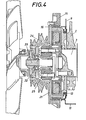
- a cross member 15 with the interposition of an elastic and structure-borne sound-absorbing ring 16, with the cross Carrier 15, which in turn is supported on longitudinal beams 17 of a chassis, auxiliary devices such as alternator 18, water pump 19 and compressor 20 (Fig. 3) are attached.
- a bearing plate 21 which is coaxial with the crankshaft 3 and serves as a cover, is screwed onto the cross member 15 and is provided with a bearing 22 for the shaft 23 of the drive pulley 24 for the auxiliary devices 18, 19, 20.
- the shaft 23 is connected to the crankshaft 3 via an elastic coupling 25 which isolates structure-borne noise.
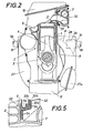
- the flywheel housing 8 has its own formwork 27 supported on it with the interposition of structure-borne sound-absorbing rings 26, which part 27a also encloses the starter. Furthermore, 8 eyes 28 are provided in the flywheel housing according to FIG. 2, which have a rubber lining 29 and are used to mount support pins 30 for the unit formed.
- the cladding 27 of the flywheel housing 8 is supported on the trunnion 30 also by means of structure-borne rings 31.
- the casing 9 has an elongated opening in the region of the exhaust manifold 7, which opening is closed by a housing 32 surrounding the exhaust manifold 7.
- the edge 9a of the opening of the casing 9 nestles against the housing 32 with the interposition of an elastic seal 33 (see in particular FIG. 5), which in this edge region of the opening consists of layers 32a, 32b, 32c separated by heat-resistant and structure-borne sound insulation 34 consists.
Landscapes
- Engineering & Computer Science (AREA)
- Physics & Mathematics (AREA)
- Acoustics & Sound (AREA)
- Chemical & Material Sciences (AREA)
- Combustion & Propulsion (AREA)
- Mechanical Engineering (AREA)
- General Engineering & Computer Science (AREA)
- Cylinder Crankcases Of Internal Combustion Engines (AREA)
Applications Claiming Priority (2)
| Application Number | Priority Date | Filing Date | Title |
|---|---|---|---|
| AT0148781A AT387624B (de) | 1981-03-31 | 1981-03-31 | Hubkolben-brennkraftmaschine |
| AT1487/81 | 1981-03-31 |
Publications (2)
| Publication Number | Publication Date |
|---|---|
| EP0062030A1 true EP0062030A1 (fr) | 1982-10-06 |
| EP0062030B1 EP0062030B1 (fr) | 1985-07-10 |
Family
ID=3514955
Family Applications (1)
| Application Number | Title | Priority Date | Filing Date |
|---|---|---|---|
| EP82890045A Expired EP0062030B1 (fr) | 1981-03-31 | 1982-03-24 | Moteur à combustion interne à piston alternatif |
Country Status (7)
| Country | Link |
|---|---|
| US (1) | US4480608A (fr) |
| EP (1) | EP0062030B1 (fr) |
| JP (1) | JPS57176345A (fr) |
| AT (1) | AT387624B (fr) |
| CA (1) | CA1189454A (fr) |
| DE (1) | DE3264630D1 (fr) |
| YU (1) | YU43512B (fr) |
Cited By (3)
| Publication number | Priority date | Publication date | Assignee | Title |
|---|---|---|---|---|
| EP0252178A1 (fr) * | 1986-07-10 | 1988-01-13 | MAN Nutzfahrzeuge Aktiengesellschaft | Enveloppe pour moteur de propulsion dans les automobiles |
| DE3831002A1 (de) * | 1987-11-03 | 1989-05-18 | Steyr Daimler Puch Ag | Verbindung der kurbelwelle einer schalldicht gekapselten brennkraftmaschine mit der koaxialen antriebswelle der ausserhalb der kapsel angeordneten hilfseinrichtungen |
| US4836160A (en) * | 1987-09-09 | 1989-06-06 | Steyr-Daimler-Puch Aktiengesellschaft | Internal combustion engine provided with a sound-insulating enclosure |
Families Citing this family (8)
| Publication number | Priority date | Publication date | Assignee | Title |
|---|---|---|---|---|
| DE3408011C2 (de) * | 1984-03-03 | 1987-03-12 | Klein, Schanzlin & Becker Ag, 6710 Frankenthal | Abdichtung für Teilflansch und Dichtungsgehäuse von längsgeteilten Maschinengehäusen |
| US4669432A (en) * | 1986-05-16 | 1987-06-02 | Kabushiki Kaisha Komatsu Seisakusho | Sealing device for an oil pan adapter in an internal combustion engine |
| ATA108690A (de) * | 1990-05-16 | 1994-12-15 | Laimboeck Franz | Flüssigkeitsgekühlte brennkraftmaschine |
| US5665019A (en) * | 1996-02-05 | 1997-09-09 | Ford Global Technologies, Inc. | Chain guide mounting assembly for the reduction of chain induced noise and vibration in a chain driven overhead cam internal combustion engine |
| US6178939B1 (en) * | 1998-06-24 | 2001-01-30 | Siemens Canada Limited | Housing system |
| DE10358117A1 (de) * | 2003-12-12 | 2005-07-14 | Man Nutzfahrzeuge Ag | Flachdichtung |
| AT503764B1 (de) * | 2007-09-06 | 2009-01-15 | Avl List Gmbh | Schwungradgehäuse |
| CN112682621B (zh) * | 2020-12-21 | 2023-01-20 | 中国北方发动机研究所(天津) | 一种集成油路的分体式飞轮壳结构 |
Citations (6)
| Publication number | Priority date | Publication date | Assignee | Title |
|---|---|---|---|---|
| GB145062A (en) * | 1915-12-18 | 1920-12-09 | Daimler Motoren | Improvements in and connected with means for preventing the transmission of sound and vibration from machines and parts thereof |
| US2875746A (en) * | 1956-05-09 | 1959-03-03 | Gen Motors Corp | Engine accessory support means |
| DE2043280A1 (de) * | 1969-09-08 | 1971-04-15 | List, Hans, Dipl Ing Prof Dr Dr h c , Graz (Österreich) | Brennkraftmaschine mit schall dämmender Verschalung |
| DE1775468A1 (de) * | 1967-08-21 | 1972-04-06 | List Hans | Brennkraftmaschine mit geraeuschdaemmender Verschalung |
| FR2307964A1 (fr) * | 1975-04-18 | 1976-11-12 | List Hans | Moteur a combustion a bruit reduit |
| DE2801431A1 (de) * | 1977-12-07 | 1979-06-13 | Steyr Daimler Puch Ag | Hubkolben-brennkraftmaschine |
Family Cites Families (9)
| Publication number | Priority date | Publication date | Assignee | Title |
|---|---|---|---|---|
| US3263663A (en) * | 1963-09-09 | 1966-08-02 | Crusader Marine Corp | Engine |
| US3863936A (en) * | 1973-03-27 | 1975-02-04 | Farnam Co F D | High temperature gasket structure and method of producing same |
| GB1451707A (en) * | 1974-07-26 | 1976-10-06 | British Uralite Ltd | Noise control materials |
| JPS5516090Y2 (fr) * | 1976-03-26 | 1980-04-15 | ||
| US4137888A (en) * | 1976-11-24 | 1979-02-06 | Allis-Chalmers Corporation | Sound abatement device for internal combustion engine |
| DE2804833A1 (de) * | 1977-02-24 | 1978-08-31 | List Hans | Geraeuscharmer verbrennungsmotor |
| DE2736378C2 (de) * | 1977-08-12 | 1985-12-19 | Klöckner-Humboldt-Deutz AG, 5000 Köln | Hilfsmaschinen für die luftgekühlte Brennkraftmaschine eines Schleppers |
| AT365309B (de) * | 1977-08-18 | 1982-01-11 | List Hans | Brennkraftmaschine mit schalldaemmender verschalung |
| AT374569B (de) * | 1979-02-07 | 1984-05-10 | List Hans | Brennkraftmaschine |
-
1981
- 1981-03-31 AT AT0148781A patent/AT387624B/de not_active IP Right Cessation
-
1982
- 1982-03-18 US US06/359,279 patent/US4480608A/en not_active Expired - Fee Related
- 1982-03-24 DE DE8282890045T patent/DE3264630D1/de not_active Expired
- 1982-03-24 EP EP82890045A patent/EP0062030B1/fr not_active Expired
- 1982-03-30 JP JP57050258A patent/JPS57176345A/ja active Granted
- 1982-03-30 CA CA000399768A patent/CA1189454A/fr not_active Expired
- 1982-03-31 YU YU718/82A patent/YU43512B/xx unknown
Patent Citations (6)
| Publication number | Priority date | Publication date | Assignee | Title |
|---|---|---|---|---|
| GB145062A (en) * | 1915-12-18 | 1920-12-09 | Daimler Motoren | Improvements in and connected with means for preventing the transmission of sound and vibration from machines and parts thereof |
| US2875746A (en) * | 1956-05-09 | 1959-03-03 | Gen Motors Corp | Engine accessory support means |
| DE1775468A1 (de) * | 1967-08-21 | 1972-04-06 | List Hans | Brennkraftmaschine mit geraeuschdaemmender Verschalung |
| DE2043280A1 (de) * | 1969-09-08 | 1971-04-15 | List, Hans, Dipl Ing Prof Dr Dr h c , Graz (Österreich) | Brennkraftmaschine mit schall dämmender Verschalung |
| FR2307964A1 (fr) * | 1975-04-18 | 1976-11-12 | List Hans | Moteur a combustion a bruit reduit |
| DE2801431A1 (de) * | 1977-12-07 | 1979-06-13 | Steyr Daimler Puch Ag | Hubkolben-brennkraftmaschine |
Non-Patent Citations (1)
| Title |
|---|
| AUTOMOBILTECHNISCHE ZEITSCHRIFT, Band 74, Nr. 7, Juli 1972, Seiten 261-268, Stuttgart, DE. * |
Cited By (5)
| Publication number | Priority date | Publication date | Assignee | Title |
|---|---|---|---|---|
| EP0252178A1 (fr) * | 1986-07-10 | 1988-01-13 | MAN Nutzfahrzeuge Aktiengesellschaft | Enveloppe pour moteur de propulsion dans les automobiles |
| US4836160A (en) * | 1987-09-09 | 1989-06-06 | Steyr-Daimler-Puch Aktiengesellschaft | Internal combustion engine provided with a sound-insulating enclosure |
| EP0307388A3 (en) * | 1987-09-09 | 1989-11-29 | Steyr-Daimler-Puch Aktiengesellschaft | Sound-absorbing encapsulation for an internal-combustion engine |
| DE3831002A1 (de) * | 1987-11-03 | 1989-05-18 | Steyr Daimler Puch Ag | Verbindung der kurbelwelle einer schalldicht gekapselten brennkraftmaschine mit der koaxialen antriebswelle der ausserhalb der kapsel angeordneten hilfseinrichtungen |
| EP0315622A3 (en) * | 1987-11-03 | 1989-11-23 | Steyr-Daimler-Puch Aktiengesellschaft | Connection of the crankshaft of an insulated internal combustion engine to the coaxial drive shaft of auxiliary devices arranged outside the encapsulation, on a transverse carrier |
Also Published As
| Publication number | Publication date |
|---|---|
| ATA148781A (de) | 1988-07-15 |
| EP0062030B1 (fr) | 1985-07-10 |
| YU43512B (en) | 1989-08-31 |
| US4480608A (en) | 1984-11-06 |
| DE3264630D1 (en) | 1985-08-14 |
| YU71882A (en) | 1985-03-20 |
| AT387624B (de) | 1989-02-27 |
| JPS6315471B2 (fr) | 1988-04-05 |
| JPS57176345A (en) | 1982-10-29 |
| CA1189454A (fr) | 1985-06-25 |
Similar Documents
| Publication | Publication Date | Title |
|---|---|---|
| DE1576775C3 (de) | Brennkraftmaschine mit schallisolierender Verschalung | |
| DE1914162C3 (de) | Luftgekühlte Einzylinderbrennkraftm aschine | |
| DE2612182C3 (de) | Geräuschgedämmte Hubkolben-Brennkraftmaschine | |
| DE1775468A1 (de) | Brennkraftmaschine mit geraeuschdaemmender Verschalung | |
| EP0062030A1 (fr) | Moteur à combustion interne à piston alternatif | |
| DE2922030A1 (de) | Brennkraftmaschine | |
| DE2801431C3 (de) | Hubkolben-Brennkraftmaschine | |
| DE2920081C2 (de) | Brennkraftmaschine, dessen Triebwerksträger über kraftübertragende und körperschallisolierende Elemente am Kurbelgehäuse abgestützt ist | |
| DE2065889A1 (de) | Brennkraftmaschine mit schalldaemmender verschalung | |
| WO1995016121A1 (fr) | Machine a piston, notamment moteur a combustion interne a piston comportant un bloc-moteur renforce | |
| EP0435847B1 (fr) | Moteur alternatif à combustion interne | |
| DE3532599C2 (fr) | ||
| DE4141881C2 (de) | Schallgedämpfte Hubkolbenbrennkraftmaschine | |
| DE9319055U1 (de) | Kolbenmaschine, insbesondere Kolbenbrennkraftmaschine mit versteiftem Motorblock mittels unterbrochener Rippen | |
| AT394759B (de) | Brennkraftmaschine mit fluessigkeitskuehlung | |
| DE3634454A1 (de) | Aus hubkolben-brennkraftmaschine, getriebe und antriebswelle bestehende antriebseinheit | |
| EP0030597B1 (fr) | Moteur à combustion interne avec arrangement de pompes d'injection | |
| EP0457750B1 (fr) | Moteur à combustion interne à refroidissement liquide | |
| AT394758B (de) | Brennkraftmaschine | |
| AT400742B (de) | Brennkraftmaschine mit hin- und hergehenden kolben | |
| AT399916B (de) | Brennkraftmaschine mit schalldämmender verschalung | |
| AT402536B (de) | Brennkraftmaschine mit hin- und hergehenden kolben | |
| DE2043280C3 (de) | Brennkraftmaschine mit schalldämmender Verschalung | |
| AT345674B (de) | Kraftfahrzeug mit auf seinen beiden rahmenholmen abgestuetztem schalldaemmend verkleidetem verbrennungsmotor | |
| DE2801431C2 (de) | Hubkolben-Brennkraftmaschine |
Legal Events
| Date | Code | Title | Description |
|---|---|---|---|
| PUAI | Public reference made under article 153(3) epc to a published international application that has entered the european phase |
Free format text: ORIGINAL CODE: 0009012 |
|
| AK | Designated contracting states |
Designated state(s): DE FR GB IT NL SE |
|
| 17P | Request for examination filed |
Effective date: 19821016 |
|
| ITF | It: translation for a ep patent filed | ||
| GRAA | (expected) grant |
Free format text: ORIGINAL CODE: 0009210 |
|
| AK | Designated contracting states |
Designated state(s): DE FR GB IT NL SE |
|
| REF | Corresponds to: |
Ref document number: 3264630 Country of ref document: DE Date of ref document: 19850814 |
|
| ET | Fr: translation filed | ||
| PLBE | No opposition filed within time limit |
Free format text: ORIGINAL CODE: 0009261 |
|
| STAA | Information on the status of an ep patent application or granted ep patent |
Free format text: STATUS: NO OPPOSITION FILED WITHIN TIME LIMIT |
|
| 26N | No opposition filed | ||
| ITTA | It: last paid annual fee | ||
| PGFP | Annual fee paid to national office [announced via postgrant information from national office to epo] |
Ref country code: GB Payment date: 19940215 Year of fee payment: 13 |
|
| PGFP | Annual fee paid to national office [announced via postgrant information from national office to epo] |
Ref country code: FR Payment date: 19940218 Year of fee payment: 13 |
|
| PGFP | Annual fee paid to national office [announced via postgrant information from national office to epo] |
Ref country code: SE Payment date: 19940223 Year of fee payment: 13 |
|
| PGFP | Annual fee paid to national office [announced via postgrant information from national office to epo] |
Ref country code: NL Payment date: 19940331 Year of fee payment: 13 |
|
| EAL | Se: european patent in force in sweden |
Ref document number: 82890045.6 |
|
| PG25 | Lapsed in a contracting state [announced via postgrant information from national office to epo] |
Ref country code: GB Effective date: 19950324 |
|
| PG25 | Lapsed in a contracting state [announced via postgrant information from national office to epo] |
Ref country code: SE Effective date: 19950325 |
|
| PG25 | Lapsed in a contracting state [announced via postgrant information from national office to epo] |
Ref country code: NL Effective date: 19951001 |
|
| GBPC | Gb: european patent ceased through non-payment of renewal fee |
Effective date: 19950324 |
|
| PG25 | Lapsed in a contracting state [announced via postgrant information from national office to epo] |
Ref country code: FR Free format text: LAPSE BECAUSE OF NON-PAYMENT OF DUE FEES Effective date: 19951130 |
|
| NLV4 | Nl: lapsed or anulled due to non-payment of the annual fee |
Effective date: 19951001 |
|
| EUG | Se: european patent has lapsed |
Ref document number: 82890045.6 |
|
| REG | Reference to a national code |
Ref country code: FR Ref legal event code: ST |
|
| PGFP | Annual fee paid to national office [announced via postgrant information from national office to epo] |
Ref country code: DE Payment date: 20010313 Year of fee payment: 20 |