EP0252308B1 - Procédé de traitement de métaux liquides et dispositif pour la mise en oeuvre dudit procédé - Google Patents
Procédé de traitement de métaux liquides et dispositif pour la mise en oeuvre dudit procédé Download PDFInfo
- Publication number
- EP0252308B1 EP0252308B1 EP87108219A EP87108219A EP0252308B1 EP 0252308 B1 EP0252308 B1 EP 0252308B1 EP 87108219 A EP87108219 A EP 87108219A EP 87108219 A EP87108219 A EP 87108219A EP 0252308 B1 EP0252308 B1 EP 0252308B1
- Authority
- EP
- European Patent Office
- Prior art keywords
- vessel
- metal
- inductors
- mixing
- melt
- Prior art date
- Legal status (The legal status is an assumption and is not a legal conclusion. Google has not performed a legal analysis and makes no representation as to the accuracy of the status listed.)
- Expired - Lifetime
Links
- 229910052751 metal Inorganic materials 0.000 title claims abstract description 72
- 239000002184 metal Substances 0.000 title claims abstract description 72
- 239000000155 melt Substances 0.000 title claims abstract description 18
- 238000000034 method Methods 0.000 title claims description 42
- 230000008569 process Effects 0.000 title description 10
- 238000009434 installation Methods 0.000 title description 2
- 238000002156 mixing Methods 0.000 claims abstract description 72
- 238000011282 treatment Methods 0.000 claims abstract description 34
- 230000033001 locomotion Effects 0.000 claims abstract description 11
- 238000005275 alloying Methods 0.000 claims abstract description 7
- 239000013543 active substance Substances 0.000 claims abstract description 5
- 239000002893 slag Substances 0.000 claims description 41
- 239000000126 substance Substances 0.000 claims description 21
- 238000006243 chemical reaction Methods 0.000 claims description 14
- 238000010438 heat treatment Methods 0.000 claims description 10
- 238000013461 design Methods 0.000 claims description 7
- 238000005192 partition Methods 0.000 claims description 5
- 239000000654 additive Substances 0.000 claims description 4
- 230000000996 additive effect Effects 0.000 claims description 3
- 230000004075 alteration Effects 0.000 claims 1
- 230000000630 rising effect Effects 0.000 claims 1
- 239000002912 waste gas Substances 0.000 claims 1
- 229910000805 Pig iron Inorganic materials 0.000 description 49
- 239000007789 gas Substances 0.000 description 29
- 230000000694 effects Effects 0.000 description 18
- 238000006477 desulfuration reaction Methods 0.000 description 15
- 230000023556 desulfurization Effects 0.000 description 15
- QVGXLLKOCUKJST-UHFFFAOYSA-N atomic oxygen Chemical compound [O] QVGXLLKOCUKJST-UHFFFAOYSA-N 0.000 description 11
- 239000003245 coal Substances 0.000 description 11
- 239000001301 oxygen Substances 0.000 description 11
- 229910052760 oxygen Inorganic materials 0.000 description 11
- 239000002699 waste material Substances 0.000 description 9
- OKTJSMMVPCPJKN-UHFFFAOYSA-N Carbon Chemical compound [C] OKTJSMMVPCPJKN-UHFFFAOYSA-N 0.000 description 8
- 229910000831 Steel Inorganic materials 0.000 description 8
- 229910052799 carbon Inorganic materials 0.000 description 8
- 239000010959 steel Substances 0.000 description 8
- 150000002739 metals Chemical class 0.000 description 7
- 235000008733 Citrus aurantifolia Nutrition 0.000 description 6
- XEEYBQQBJWHFJM-UHFFFAOYSA-N Iron Chemical compound [Fe] XEEYBQQBJWHFJM-UHFFFAOYSA-N 0.000 description 6
- 235000011941 Tilia x europaea Nutrition 0.000 description 6
- HCHKCACWOHOZIP-UHFFFAOYSA-N Zinc Chemical compound [Zn] HCHKCACWOHOZIP-UHFFFAOYSA-N 0.000 description 6
- 230000009471 action Effects 0.000 description 6
- 238000007792 addition Methods 0.000 description 6
- 239000004571 lime Substances 0.000 description 6
- 229910052725 zinc Inorganic materials 0.000 description 6
- 239000011701 zinc Substances 0.000 description 6
- 239000003795 chemical substances by application Substances 0.000 description 5
- 238000002309 gasification Methods 0.000 description 5
- 239000007788 liquid Substances 0.000 description 5
- 238000004519 manufacturing process Methods 0.000 description 5
- 239000007787 solid Substances 0.000 description 5
- CDBYLPFSWZWCQE-UHFFFAOYSA-L Sodium Carbonate Chemical compound [Na+].[Na+].[O-]C([O-])=O CDBYLPFSWZWCQE-UHFFFAOYSA-L 0.000 description 4
- 238000007664 blowing Methods 0.000 description 4
- 239000000428 dust Substances 0.000 description 4
- 238000005086 pumping Methods 0.000 description 4
- 239000005997 Calcium carbide Substances 0.000 description 3
- 239000000956 alloy Substances 0.000 description 3
- 229910045601 alloy Inorganic materials 0.000 description 3
- 238000010924 continuous production Methods 0.000 description 3
- 230000001965 increasing effect Effects 0.000 description 3
- 230000001939 inductive effect Effects 0.000 description 3
- 238000003780 insertion Methods 0.000 description 3
- 230000037431 insertion Effects 0.000 description 3
- 229910052742 iron Inorganic materials 0.000 description 3
- 239000000463 material Substances 0.000 description 3
- 238000002844 melting Methods 0.000 description 3
- 230000008018 melting Effects 0.000 description 3
- 239000000203 mixture Substances 0.000 description 3
- CLZWAWBPWVRRGI-UHFFFAOYSA-N tert-butyl 2-[2-[2-[2-[bis[2-[(2-methylpropan-2-yl)oxy]-2-oxoethyl]amino]-5-bromophenoxy]ethoxy]-4-methyl-n-[2-[(2-methylpropan-2-yl)oxy]-2-oxoethyl]anilino]acetate Chemical compound CC1=CC=C(N(CC(=O)OC(C)(C)C)CC(=O)OC(C)(C)C)C(OCCOC=2C(=CC=C(Br)C=2)N(CC(=O)OC(C)(C)C)CC(=O)OC(C)(C)C)=C1 CLZWAWBPWVRRGI-UHFFFAOYSA-N 0.000 description 3
- VTYYLEPIZMXCLO-UHFFFAOYSA-L Calcium carbonate Chemical compound [Ca+2].[O-]C([O-])=O VTYYLEPIZMXCLO-UHFFFAOYSA-L 0.000 description 2
- NINIDFKCEFEMDL-UHFFFAOYSA-N Sulfur Chemical compound [S] NINIDFKCEFEMDL-UHFFFAOYSA-N 0.000 description 2
- 229910052782 aluminium Inorganic materials 0.000 description 2
- XAGFODPZIPBFFR-UHFFFAOYSA-N aluminium Chemical compound [Al] XAGFODPZIPBFFR-UHFFFAOYSA-N 0.000 description 2
- 239000004568 cement Substances 0.000 description 2
- 239000002131 composite material Substances 0.000 description 2
- 239000000945 filler Substances 0.000 description 2
- 230000006698 induction Effects 0.000 description 2
- 238000009856 non-ferrous metallurgy Methods 0.000 description 2
- 230000001590 oxidative effect Effects 0.000 description 2
- 230000009467 reduction Effects 0.000 description 2
- 230000001105 regulatory effect Effects 0.000 description 2
- 238000000926 separation method Methods 0.000 description 2
- 239000000161 steel melt Substances 0.000 description 2
- 229910052717 sulfur Inorganic materials 0.000 description 2
- 239000011593 sulfur Substances 0.000 description 2
- 239000011269 tar Substances 0.000 description 2
- XLYOFNOQVPJJNP-UHFFFAOYSA-N water Chemical compound O XLYOFNOQVPJJNP-UHFFFAOYSA-N 0.000 description 2
- 244000089486 Phragmites australis subsp australis Species 0.000 description 1
- XUIMIQQOPSSXEZ-UHFFFAOYSA-N Silicon Chemical compound [Si] XUIMIQQOPSSXEZ-UHFFFAOYSA-N 0.000 description 1
- 241001311504 Torpedo sinuspersici Species 0.000 description 1
- PIYVNGWKHNMMAU-UHFFFAOYSA-N [O].O Chemical compound [O].O PIYVNGWKHNMMAU-UHFFFAOYSA-N 0.000 description 1
- 238000005299 abrasion Methods 0.000 description 1
- 230000001133 acceleration Effects 0.000 description 1
- 230000002378 acidificating effect Effects 0.000 description 1
- PNEYBMLMFCGWSK-UHFFFAOYSA-N aluminium oxide Inorganic materials [O-2].[O-2].[O-2].[Al+3].[Al+3] PNEYBMLMFCGWSK-UHFFFAOYSA-N 0.000 description 1
- 239000002956 ash Substances 0.000 description 1
- 229910000019 calcium carbonate Inorganic materials 0.000 description 1
- 238000005266 casting Methods 0.000 description 1
- 230000008859 change Effects 0.000 description 1
- 238000004140 cleaning Methods 0.000 description 1
- 239000010883 coal ash Substances 0.000 description 1
- 238000002485 combustion reaction Methods 0.000 description 1
- 239000000470 constituent Substances 0.000 description 1
- 238000001816 cooling Methods 0.000 description 1
- 238000007872 degassing Methods 0.000 description 1
- 230000003009 desulfurizing effect Effects 0.000 description 1
- 238000011161 development Methods 0.000 description 1
- 230000018109 developmental process Effects 0.000 description 1
- 238000010586 diagram Methods 0.000 description 1
- 230000002349 favourable effect Effects 0.000 description 1
- 230000009970 fire resistant effect Effects 0.000 description 1
- 230000004907 flux Effects 0.000 description 1
- 210000001061 forehead Anatomy 0.000 description 1
- 238000000265 homogenisation Methods 0.000 description 1
- 239000004615 ingredient Substances 0.000 description 1
- 238000002347 injection Methods 0.000 description 1
- 239000007924 injection Substances 0.000 description 1
- UQSXHKLRYXJYBZ-UHFFFAOYSA-N iron oxide Inorganic materials [Fe]=O UQSXHKLRYXJYBZ-UHFFFAOYSA-N 0.000 description 1
- 235000013980 iron oxide Nutrition 0.000 description 1
- VBMVTYDPPZVILR-UHFFFAOYSA-N iron(2+);oxygen(2-) Chemical class [O-2].[Fe+2] VBMVTYDPPZVILR-UHFFFAOYSA-N 0.000 description 1
- 239000011133 lead Substances 0.000 description 1
- 230000003647 oxidation Effects 0.000 description 1
- 238000007254 oxidation reaction Methods 0.000 description 1
- 239000000843 powder Substances 0.000 description 1
- 238000010926 purge Methods 0.000 description 1
- 230000005855 radiation Effects 0.000 description 1
- 230000036632 reaction speed Effects 0.000 description 1
- 230000009257 reactivity Effects 0.000 description 1
- 238000010079 rubber tapping Methods 0.000 description 1
- 229910052710 silicon Inorganic materials 0.000 description 1
- 239000010703 silicon Substances 0.000 description 1
- VYPSYNLAJGMNEJ-UHFFFAOYSA-N silicon dioxide Inorganic materials O=[Si]=O VYPSYNLAJGMNEJ-UHFFFAOYSA-N 0.000 description 1
- 239000000377 silicon dioxide Substances 0.000 description 1
- 238000012360 testing method Methods 0.000 description 1
- 229960005486 vaccine Drugs 0.000 description 1
- 238000004056 waste incineration Methods 0.000 description 1
Images


Classifications
-
- C—CHEMISTRY; METALLURGY
- C21—METALLURGY OF IRON
- C21C—PROCESSING OF PIG-IRON, e.g. REFINING, MANUFACTURE OF WROUGHT-IRON OR STEEL; TREATMENT IN MOLTEN STATE OF FERROUS ALLOYS
- C21C1/00—Refining of pig-iron; Cast iron
-
- B—PERFORMING OPERATIONS; TRANSPORTING
- B01—PHYSICAL OR CHEMICAL PROCESSES OR APPARATUS IN GENERAL
- B01F—MIXING, e.g. DISSOLVING, EMULSIFYING OR DISPERSING
- B01F33/00—Other mixers; Mixing plants; Combinations of mixers
- B01F33/45—Magnetic mixers; Mixers with magnetically driven stirrers
- B01F33/451—Magnetic mixers; Mixers with magnetically driven stirrers wherein the mixture is directly exposed to an electromagnetic field without use of a stirrer, e.g. for material comprising ferromagnetic particles or for molten metal
-
- C—CHEMISTRY; METALLURGY
- C21—METALLURGY OF IRON
- C21C—PROCESSING OF PIG-IRON, e.g. REFINING, MANUFACTURE OF WROUGHT-IRON OR STEEL; TREATMENT IN MOLTEN STATE OF FERROUS ALLOYS
- C21C5/00—Manufacture of carbon-steel, e.g. plain mild steel, medium carbon steel or cast steel or stainless steel
- C21C5/52—Manufacture of steel in electric furnaces
- C21C5/5241—Manufacture of steel in electric furnaces in an inductively heated furnace
- C21C5/5247—Manufacture of steel in electric furnaces in an inductively heated furnace processing a moving metal stream while exposed to an electromagnetic field, e.g. in an electromagnetic counter current channel
-
- C—CHEMISTRY; METALLURGY
- C22—METALLURGY; FERROUS OR NON-FERROUS ALLOYS; TREATMENT OF ALLOYS OR NON-FERROUS METALS
- C22B—PRODUCTION AND REFINING OF METALS; PRETREATMENT OF RAW MATERIALS
- C22B9/00—General processes of refining or remelting of metals; Apparatus for electroslag or arc remelting of metals
- C22B9/02—Refining by liquating, filtering, centrifuging, distilling, or supersonic wave action including acoustic waves
-
- C—CHEMISTRY; METALLURGY
- C22—METALLURGY; FERROUS OR NON-FERROUS ALLOYS; TREATMENT OF ALLOYS OR NON-FERROUS METALS
- C22B—PRODUCTION AND REFINING OF METALS; PRETREATMENT OF RAW MATERIALS
- C22B9/00—General processes of refining or remelting of metals; Apparatus for electroslag or arc remelting of metals
- C22B9/10—General processes of refining or remelting of metals; Apparatus for electroslag or arc remelting of metals with refining or fluxing agents; Use of materials therefor, e.g. slagging or scorifying agents
- C22B9/103—Methods of introduction of solid or liquid refining or fluxing agents
-
- H—ELECTRICITY
- H05—ELECTRIC TECHNIQUES NOT OTHERWISE PROVIDED FOR
- H05B—ELECTRIC HEATING; ELECTRIC LIGHT SOURCES NOT OTHERWISE PROVIDED FOR; CIRCUIT ARRANGEMENTS FOR ELECTRIC LIGHT SOURCES, IN GENERAL
- H05B6/00—Heating by electric, magnetic or electromagnetic fields
- H05B6/02—Induction heating
- H05B6/34—Arrangements for circulation of melts
-
- B—PERFORMING OPERATIONS; TRANSPORTING
- B01—PHYSICAL OR CHEMICAL PROCESSES OR APPARATUS IN GENERAL
- B01F—MIXING, e.g. DISSOLVING, EMULSIFYING OR DISPERSING
- B01F2101/00—Mixing characterised by the nature of the mixed materials or by the application field
- B01F2101/45—Mixing in metallurgical processes of ferrous or non-ferrous materials
-
- Y—GENERAL TAGGING OF NEW TECHNOLOGICAL DEVELOPMENTS; GENERAL TAGGING OF CROSS-SECTIONAL TECHNOLOGIES SPANNING OVER SEVERAL SECTIONS OF THE IPC; TECHNICAL SUBJECTS COVERED BY FORMER USPC CROSS-REFERENCE ART COLLECTIONS [XRACs] AND DIGESTS
- Y02—TECHNOLOGIES OR APPLICATIONS FOR MITIGATION OR ADAPTATION AGAINST CLIMATE CHANGE
- Y02P—CLIMATE CHANGE MITIGATION TECHNOLOGIES IN THE PRODUCTION OR PROCESSING OF GOODS
- Y02P10/00—Technologies related to metal processing
- Y02P10/20—Recycling
-
- Y—GENERAL TAGGING OF NEW TECHNOLOGICAL DEVELOPMENTS; GENERAL TAGGING OF CROSS-SECTIONAL TECHNOLOGIES SPANNING OVER SEVERAL SECTIONS OF THE IPC; TECHNICAL SUBJECTS COVERED BY FORMER USPC CROSS-REFERENCE ART COLLECTIONS [XRACs] AND DIGESTS
- Y02—TECHNOLOGIES OR APPLICATIONS FOR MITIGATION OR ADAPTATION AGAINST CLIMATE CHANGE
- Y02P—CLIMATE CHANGE MITIGATION TECHNOLOGIES IN THE PRODUCTION OR PROCESSING OF GOODS
- Y02P10/00—Technologies related to metal processing
- Y02P10/25—Process efficiency
Definitions
- the invention relates to a method for treating molten metals by adding chemically active substances or alloying elements, the molten metal being set in motion in a suitable, essentially cylindrical vessel by means of electromagnetic force.
- the invention also relates to an apparatus for performing this method.
- Metal melts in particular iron and steel melts, are usually treated by intimate mixing with chemically active agents which are added to the melt in a solid, liquid or gaseous state.
- Pig iron melting is desulfurized or dephosphorized by using e.g. Soda or basic oxidizing slags are mixed.
- Steel melts are also e.g. treated for deoxidation or desulphurization by mixing them with powders or slag mostly in pans.
- Alloy elements are also introduced into the metals by intimate mixing with them. Chemical reactions are also achieved by intimately mixing solid substances with molten metals.
- Coals are gasified by introducing them into pig iron melts, which are oxidized at the same time or subsequently. It has also been proposed in Luxembourg Patent No. 81,330 to treat dusts containing zinc or zinc and lead (furnace dust) by blowing them into a pig iron bath, possibly with the addition of carbon, with a separation of lead and zinc on the one hand possible and on the other hand the iron can be recovered in a reduced form.
- a classic way of introducing powdery or granulated substances into metal baths is to suspend the substances to be introduced into a gas stream and to introduce them onto or into the bath by means of lances.
- larger quantities of the substances to be treated are brought out again by the gas stream during this blowing and the reactions are thus lost.
- the object of the present invention is to provide a method and a device which facilitate the introduction of the substances and enable better mixing of the melt with the ingredients, regardless of whether the latter are added in solid, liquid or even gaseous form.
- the method according to this invention facilitates the introduction of a wide variety of substances into metal baths, particularly when it comes to finely divided substances, which in this case can be introduced into the metal without loss.
- the method according to this invention leads to a considerable acceleration of the process in such a way that one can either make do with smaller systems or, as in the case of the blast furnace channels, the multiple path between blast furnace and pans, e.g. Desilization and then dephosphorization or desulphurization.
- the method according to the invention differs significantly from the metal treatment methods known up to now by induction.
- the method according to the invention can be used both in channels, e.g. can be used to transport the pig iron between racking on the blast furnace and the transport pans, as well as in channel-shaped furnaces in which the length corresponds at least to the diameter of the furnace.
- Furnaces can also be used within the scope of the invention in which a partial amount of the metal is removed from a larger furnace just below the surface from a part of the furnace through a channel and through the same channel another part of the furnace or another furnace flows, the transport of the metal between the exit from the furnace into the channel and the entry from the channel into the furnace can be accomplished by separate inductors or by the inductors used to swirl the metal.
- a large furnace it can be separated by an intermediate wall, and a connection between the two furnace parts can be provided in the lower part of this intermediate wall.
- This composite furnace which is separated by a partition, can be replaced by two furnaces connected in its lower part.
- the inductor (s) can move perpendicular to the channel or furnace axis.
- the inductors arranged in parallel can cause their movement in the same direction of rotation.
- these inductors can also be arranged in a very advantageous manner in such a way that, in addition to conveying the metal around the channel axis, they are simultaneously used to convey the metal in a substantially horizontal or increasing direction.
- Last application which e.g. Can be achieved by helicoidally aligned inductors around the longitudinal axis, leads to the possibility of performing metallurgical reactions in countercurrent, the bath-slag reactions can be significantly improved due to the equilibrium conditions.
- the inductors can be fixed to the treatment apparatus and can only be attached to other treatment apparatus after the refractory lining has worn out. In many cases, however, it is particularly advantageous to arrange the inductors in such a way that the treatment vessels can be easily pushed into the inductors, so that many treatments can be carried out with the same inductors. Naturally, the treatment apparatus must be made from materials that do not or hardly interfere with the action of the inductors.
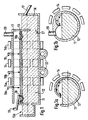
- the furnace shown in Figures 1, 1a and 1b consists of a refractory lining 11, which contains the metal 12 and the slag 13.
- One or more inductors known per se convey the metal to the top of the furnace, where it may be supported by a suitable embodiment of the refractory jacket, fall back onto the metal bath or the slag or be conveyed back and thus lead to an intimate mixing of the metal slag.
- the inductor (s) can be arranged in a sector 14, but can also be arranged on a plurality of sectors 14, 14a and 14b arranged in parallel.
- the channel furnace shown in Figure 1 is for continuous use e.g. thought in a blast furnace trough, the pig iron flowing into the gutter furnace through the gutter indicated by 15 and leaving the gutter furnace after crossing the siphon 16 via gutter 17.
- the slag 13 can flow off via the channels 18 and 18a, the furnace operating in an advantageous countercurrent with the exclusive use of the channel 18.
- the substances or gases used for metal treatment are fed to the furnace through the nozzles and / or lances 19, 19a and 19b.
- the furnace shown in Figure 1 is intended for continuous continuous operation. If one wants to use the same or a similar device for a discontinuous operation, the siphon 16 is replaced by a device known per se, e.g. a tap hole replaced or the furnace designed as a tilting furnace.
- a device known per se e.g. a tap hole replaced or the furnace designed as a tilting furnace.
- FIG. 2 shows a furnace similar to that of FIG. 1, but the inductors are arranged helically, with work in countercurrent being favored since the metal is increasingly moved from left to right by the inductors, the Slag is displaced from right to left.
- Normal torpedo pans which are normally used to transport pig iron between the blast furnace and the steelworks, can also be used for metal treatment, in particular for desulphurization.
- the pans which are not completely filled and should have a free space of at least 25 cm from the upper edge of pig iron to the pan vault, can be equipped directly with inductors according to FIG. 1 or 2 or introduced into a device which is equipped with such inductors is and can drive these inductors up to the pan wall.
- the inductors When the inductors are put into operation, the pig iron is brought up to the crown as described above and falls on the bath loaded with known additives such as soda, calcium carbide, lime dust or mixtures of these substances, with an intensive mixing and reactivity of these substances with the pig iron bath becomes.
- Another very interesting field of application of the invention is the treatment of foundry iron for desulfurization or alloying purposes in the foreheads of the dome furnaces, the transport or alloy pans or in the foundry transport vessels with which the pig iron is distributed into the casting molds.
- the alloying agents or vaccines can be mixed intensively before or after the pans are filled with pig iron, the pan designed as a channel furnace being equipped with inductors or, as previously described for the torpedo pans, being run into an inductor stand for a few minutes and be intimately mixed with the alloying and inoculating elements.
- the inductors can be attached to both sides of the pan and act in the opposite direction in order to achieve an even faster and more intensive mixing in this way.
- the invention has proven particularly useful in the removal of metal-containing waste products, such as those that arise particularly in steel production or in waste incineration. These waste products are in the form of finely divided dusts, which are difficult to treat. It is known to blow these dusts into a pig iron bath, as already described in the Luxembourg patent No. 81 330. However, this method is difficult to use because the finely divided substances are carried away in part by the conveying gases and discharged again.
- the method according to the invention enables intimate contact between pig iron and metal-containing waste products without the use of conveying gas.
- the ovens described in FIGS. 1 and 1b or 2 can be used, the filler neck 15 naturally being omitted and the oven being closed. The filling then takes place via the siphon 15a. In this case, the furnace is provided with a degassing nozzle 20.
- the process can be carried out in a continuous process e.g. in the pig iron gutter as well as a pure treatment process.
- the pig iron Used as a continuous process, the pig iron is introduced into the channel furnace through the siphon 15a, and the waste products to be treated are introduced into the system through the nozzles 19, 19a and 19b.
- the inductors Through the actions of the inductors, intimate mixing is brought about in the system, with all metals being reduced and partly escaping through the nozzle 20 in the form of steam and partly e.g. in the case of lead, accumulate in pig iron.
- the vaporous metals are condensed as metal after leaving the connector 20 or deposited after oxidation in normal filter systems.
- the iron oxides contained in the waste products are also reduced and leave the system with the pig iron via the siphon 16 and the outflow channel 17. Lead is periodically discharged via the tap 21. The slag leaves the system via rack 18 or 18a.
- the pig iron is only introduced until the furnace is filled, after which the treatment can begin by starting up the inductors and introducing the metal-containing waste products.
- the treatment is identical to that described above, with the exception that the pig iron should be set to a constant value by a possible addition of carbon with the waste products and the temperature by suitable heating systems e.g. must be maintained by the channel inductor (s) 22.
- the mixed inductors can also be designed so that they also act as heating inductors.
- the metal melt is raised to the apex of the cylindrical vessel or furnace wall by inductive rotation and then falls back or is returned to the metal bath. This creates double turbulence in the molten metal, which promotes vigorous mixing.
- Figure 4 shows the diagram of a channel system, which desilates, dephosphorized and desulfurized at the same time. It understands three siphons S1, S2 and S3 with three siphon walls 30a, 30b and 30c, as well as three mixing sections with mixing devices 32a, 32b and 32c.
- Such a system can be used in the furnace channel between the furnace and the transport pan, but it can also be used as an intermediate element between the torpedo pan and the steelworks pan.
- the pig iron R is tipped, for example, from a pig iron pan into the first siphon device, from where the slag can flow out through the opening 34a.
- preheated mill scale with flux W is added, which flows back in the direction of the siphon S1 and largely removes the pig iron.
- This route is either acidic or lined with a high alumina feed.
- the high-silica slag is separated through the opening 34b.
- the pig iron falls into the siphon S2, where silicon-containing slag residues flow out through the opening 34c.
- dephosphorization takes place in the next electromagnetic mixing device 32b, which has a curved shape.
- These arrangements were chosen to give the soda S, which was added as a dephosphoric agent in this example, the opportunity to liquefy before being countercurrently sent to S2 where it can react and drain through port 34d.
- the dephosphorization reaction is supported in the mixing device by introducing oxygen or gases containing oxygen (not shown).
- the treated pig iron flows into the siphon device S3, where traces of slag left behind can flow out through the opening 34e.
- the pig iron enters the horizontal or downstream (1 to 3 °) electromagnetic mixing system 32c, where calcium carbide K is added directly behind the siphon wall 30c.
- the hot metal with its desulfurization slag flows into a pan 36, where a subsequent desulphurization, supported by purge gas 38, may still take place.
- the main purpose of this operation is to protect the pig iron from radiation losses through the desulfurization slag layer.
- the systems 32b and 32c are preferably to be provided with a basic lining.
- the effect of the electromagnetic force which effects the rotational movement of the melt can be significantly increased by conducting an electrical current through the axis of the metal bath to be moved.
- This current is advantageously introduced into the metal bath through electrodes (not shown), which are located before and after the point to be moved.
- the current can be three-phase or direct current, but the highest efficiency is achieved with direct current.
- the method according to the invention relates not only to elongated ovens but also to other ovens or pans, in each of which only partial quantities are removed and returned to the oven, or ovens which are operated together in such a way that a continuous process is created.
- FIG. 5a represents a top view
- FIG. 5b represents a frontal side view
- FIG. 5c which combines a section with a side view.
- the pan or oven 51 lined with refractory contains the metal 52 which fills the pan to the N level.
- a slag film or slag layer S normally floats on the metal bath.
- the device 53 is introduced into the metal bath, in most cases care must be taken to ensure that the slag does not enter the device.
- the device 53 is filled with metal. This filling can be effected by switching on the inductor (s) 55, which are designed in such a way that they exert a pumping action on the metal bath, and thus convey the metal into the mixing section provided with the treatment inductors 54.
- the mode of operation of the inductors 54 corresponds to that which has already been described, in which case the inductors are preferably designed in such a way that they ensure that the metal is conveyed from right to left. They can also be designed in such a way that they cause a heating effect in addition to the mixing and conveying effect.
- the solids or liquids or gases required for the treatment can be fed through the openings or nozzles 59, 59a and 59b to the metal bath and be intimately mixed with this.
- a device similar to that just described is that the mixing section provided with the inductors is direct, i.e. without the riser section provided with the lifting inductor 55, would be connected to one or two openings in the pan and possibly provided with slide closures, which would lead to a result similar to that previously described.
- Such a device leads to very favorable results in tilting pans and in particular in torpedo pans.
- the filling of the mixing device can be easily achieved by simply tilting the pan, and with sufficient pumping and lifting action of the inductors 54, the filling can be achieved by overflowing into the pans through a normal opening.
- the mixing section just described with direct contact with the metal could be attached to the device for treating molten metals described in EP-B1 0 094 334, the heating described in this patent application being accompanied by a simultaneous treatment of the Metal can be combined according to the present invention.
- FIGS. 5a, 5b and 5c show a device in which, by means of a magnetic pumping effect, the metal which is too hard is conveyed from a pan into the mixing device according to the invention.
- the magnetic pump effect can be supported or replaced by other known means.
- the magnetic pump effect can be supported or replaced by an overpressure in the pan, by a gas lift effect or by vacuum, the four means mentioned, i.e. Overpressure in the pan, gas lifting effect, vacuum, electroinductive pumping can be used alone or in combination of the individual or different or all of the means mentioned.
- FIGS. 6 and 6a describe such a system in connection with torpedo ladles, in which the desired operations such as desiliconization, desulfurization, dephosphorization can be carried out in succession.
- this torpedo pan has a second opening 62, both openings preferably being able to be closed in a gastight manner. If this is not possible, a partition 63, which extends approximately to the center of the torpedo pan, is provided.
- the device understands a riser pipe 65 which protrudes to just above the bottom of the torpedo pan and is preferably provided with a gas lift system.
- the upper part of the riser pipe can be provided with a suction line 66.
- the electromagnetic pump shown in FIG. 5 can also be installed in the riser pipe 65.
- the torpedo pan itself can be subjected to a slight overpressure such that the pig iron fills the tube 65 and reaches the mixing sections 64 or 64a and 64b. If the inlet of the torpedo pan is not easy to seal, it is sufficient to pressurize only the right part of the torpedo pan after installing the intermediate wall 63.
- the filling or siphon device 69 which is connected to the entire system, is inserted into the normal insertion nozzle of the torpedo pan, 61.
- This device consists of a siphon vessel with a partition, a ladle insertion nozzle 68 and a slag overflow 67.
- the nozzle 68 can be closed with a melting plate 69a or with a plug 69b at the beginning of the operation.
- the slag generated during the treatment automatically flows off over the overflow 67, so that the treatments such as desulfurization, desiliconization and dephosphorization can be carried out in succession without any problems.
- the mixing sections 64, or 64a and 64b have a sufficient gradient, for example over 2 ° , so that the slag is not entrained with the metal stream, then it is possible to work in countercurrent, the additions being carried out at the ends of the mixing section and the slag over the Overflow 67a runs out of the socket 65a designed as a siphon.
- the device just described could also be used in normal pans containing pig iron, steel or other metals.
- the desired operations such as desiliconization, dephosphorization and desulfurization can preferably be carried out successively in the same pan, e.g. Torpedo pans can be carried out with the same device using means known per se.
- the individual operations are favored by the automatic intermediate deslagging.
- Operations such as the treatment of waste products containing zinc and lead with pig iron described with reference to FIG. 1 can also be carried out in the systems described.
- Steel baths can also be treated in the manner described in the production furnace itself or in the pouring ladle or intermediate ladle with the described device using known means.
- Steel baths are easily alloyed with powdery alloy elements or with known treatment slags such as solid or liquid Perrin slags are desulfurized or deoxidized.
- the reaction described in this process can be combined with the device according to the invention just described under FIGS. 5a, 5b or 5c, the aluminum addition e.g. can take place through the nozzle 59, and the subsequently required oxygen is introduced through the nozzles 59a and 59b.
- the intimate mixing which can be achieved by the device according to the invention between the steel treated with aluminum and the oxygen subsequently introduced leads to a very rapid heating effect, combined with a simultaneous cleaning effect due to the slag produced during the reaction.
- the first example is shown in FIGS. 7 and 7a and relates to a coal gasification plant of coal with a relatively low sulfur content.
- the system basically consists of two containers 71 and 72 which are connected in the upper part to the mixing section 74.
- a tube 75 connects the two vessels in their lower part.
- the system is provided with a fire-resistant lining 73.
- the system is closed with the covers 76 in such a way that it can also work under pressure.
- the vessel 7 is equipped with a lance 85, which optionally blows oxygen with lime dust onto the pig iron bath designated 79.
- the oxygen possibly with added lime, can also be fed to the pig iron bath 79 through floor nozzles 85a, which nozzles are designed as oil- or gas-cooled annular gap nozzles.
- This supply of oxygen creates the gas by burning the carbon contained in the pig iron.
- the heat generated can be regulated by adding water vapor to the injected oxygen.
- the heat that occurs can also be used to melt scrap or pre-reduced ores, which are introduced into the vessel 71 through the opening 86.
- all or part of the gases produced can be used for the pre-reduction of ores.
- the centerpiece of the system is the mixing section in the form of a connecting trough 74, which is designed as an electroinductive mixing device, as described in relation to FIG. 1.
- This gutter which naturally consists of a magnetically permeable jacket, such as Non-magnetic steel, or should advantageously consist of an non-magnetic composite material, is lined on the inside with a highly refractory and abrasion-resistant material.
- This channel 74 should be designed such that the metal 79 is conveyed from 71 to 72.
- the inductor (s) 81 are designed in such a way that, in addition to their intensive mixing effect, they also promote the metal from 71 to 72.
- the channel 74 has the filler neck 82 through which the carbon is introduced into the system.
- the channel 74 can be arranged in the furnace 71 in such a way that the slag, in this case a desulphurization slag, which mainly consists of lime with possibly a flow path additive, is conveyed from 71 to 72.
- the slag in this case a desulphurization slag, which mainly consists of lime with possibly a flow path additive, is conveyed from 71 to 72.
- the coal introduced by 82 is immediately associated with the premelted desulfurization slag and the pig iron, so that the pig iron is not only carburized by the carbon, but is also desulfurized.
- the volatile constituents of the coal can be discharged separately via gas line 83 together with the valuable tars as rich gas, the gas resulting from the oxygen-water vapor injection into 71 being able to be discharged via 83a. If you want to have a sharp separation of the gases, you have to insert the connecting and mixing tube 74 into the vessel 71 under the bath level. In this case, however, the liquid slag desulfurization effect has to be dispensed with and the desulfurization agents introduced with the coal.
- the exhaust pipe 83 is closed and all gases are discharged via 83a.
- the tars are then cracked in the hot gas space above the bath 79 in the vessel 71.
- the slags 80 leave the system via an outlet 77, possibly together with a light one hot metal surplus. If cooling is carried out with scrap or with pre-reduced ore, the pig iron made from these materials is tapped through the tap holes 78 or 84.
- FIGS. 7 and 7a can be used for a wide variety of metallurgical work.
- this plant can be used for the treatment of lead and zinc-containing metallurgical waste, as already described, the electrical heating being replaced by carbon combustion using oxygen in this plant.
- the connecting piece of the mixing and conveying trough 74 is moved into the vessel 71 under the bath level N, and the substances to be treated, possibly with added carbon, are introduced through 82.
- the gases containing lead and zinc leave the system via the nozzle of the exhaust pipe 83.
- the temperature is regulated by injecting smaller amounts of oxygen via the lance 85 and / or the floor nozzles 85a.
- the slag leaves, possibly with pig iron, the vessel 72 via the overflow 77, pig iron can be discharged via the outlet 78 or together with lead via the outlet 84.
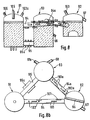
- Figures 8 and 8b schematically represent a system with three containers 91, 92, 93 and two mixing sections 94, 94a. This system already allows more complex treatments such as e.g. Gasification of coal with a higher sulfur content and simultaneous cement production.
- coal is gasified with oxygen and possibly water vapor, as in the previous example.
- the carbon with lime dust is introduced through the nozzles 102 and mixed intensively with the pig iron by the described action of the inductors 101.
- the lime additive is calculated in such a way that the coal ash results in a composition suitable for cement production.
- the slag formed in this way is separated from the container 92 via a channel 97, a siphon wall 96, which is interrupted at the bottom, possibly preventing this slag from being entrained into the mixing section 94a.
- the main desulfurization is carried out in this mixing section 94a, with desulfurizing agents known from the connecting pieces 102a, such as e.g. Soda or calcium carbonate mixtures are introduced and are intimately mixed with the pig iron through the action of inductors 101a.
- desulfurizing agents known from the connecting pieces 102a such as e.g. Soda or calcium carbonate mixtures are introduced and are intimately mixed with the pig iron through the action of inductors 101a.
- the resulting desulfurization slag is separated from the container 93 via 97a, the pig iron flowing back into the vessel 91 via 95a.
- the amount flowing back can be controlled via the solenoid and pump valve 95a.
- the gases or pig iron produced are removed from the system as shown in FIG.
- the number of vessels and inductive microtubes can be increased as desired.
- these channels are designed as straight tubes, which, in contrast to the embodiment in FIG. 7a, considerably facilitates the lining of these channels.
- the circular-arc-shaped channel shown in FIG. 7a could be replaced by a straight-line channel with good success.
- the system receives additional energy e.g. in the form of electrical energy by means of induction coils or arcs or via the treatment inductors themselves.
Landscapes
- Chemical & Material Sciences (AREA)
- Engineering & Computer Science (AREA)
- Materials Engineering (AREA)
- Metallurgy (AREA)
- Organic Chemistry (AREA)
- Manufacturing & Machinery (AREA)
- Physics & Mathematics (AREA)
- Electromagnetism (AREA)
- Mechanical Engineering (AREA)
- Chemical Kinetics & Catalysis (AREA)
- Acoustics & Sound (AREA)
- Manufacture And Refinement Of Metals (AREA)
- Refinement Of Pig-Iron, Manufacture Of Cast Iron, And Steel Manufacture Other Than In Revolving Furnaces (AREA)
- Manufacture Of Alloys Or Alloy Compounds (AREA)
- Crucibles And Fluidized-Bed Furnaces (AREA)
- Coating With Molten Metal (AREA)
Claims (29)
Priority Applications (1)
| Application Number | Priority Date | Filing Date | Title |
|---|---|---|---|
| AT87108219T ATE51417T1 (de) | 1986-06-12 | 1987-06-06 | Verfahren zum behandeln von metallschmelzen und vorrichtung zum durchfuehren des verfahrens. |
Applications Claiming Priority (4)
| Application Number | Priority Date | Filing Date | Title |
|---|---|---|---|
| LU86469 | 1986-06-12 | ||
| LU86469A LU86469A1 (de) | 1986-06-12 | 1986-06-12 | Verfahren bzw.vorrichtung zum behandeln von metallschmelzen |
| LU86541 | 1986-08-05 | ||
| LU86541A LU86541A7 (de) | 1986-08-05 | 1986-08-05 | Verfahren und vorrichtung zum behandeln von metallschmelzen |
Publications (2)
| Publication Number | Publication Date |
|---|---|
| EP0252308A1 EP0252308A1 (fr) | 1988-01-13 |
| EP0252308B1 true EP0252308B1 (fr) | 1990-03-28 |
Family
ID=26640319
Family Applications (1)
| Application Number | Title | Priority Date | Filing Date |
|---|---|---|---|
| EP87108219A Expired - Lifetime EP0252308B1 (fr) | 1986-06-12 | 1987-06-06 | Procédé de traitement de métaux liquides et dispositif pour la mise en oeuvre dudit procédé |
Country Status (8)
| Country | Link |
|---|---|
| US (2) | US4808219A (fr) |
| EP (1) | EP0252308B1 (fr) |
| JP (1) | JPH086131B2 (fr) |
| AT (1) | ATE51417T1 (fr) |
| CA (1) | CA1328563C (fr) |
| DE (1) | DE3762049D1 (fr) |
| ES (1) | ES2014276B3 (fr) |
| GR (1) | GR3000554T3 (fr) |
Families Citing this family (9)
| Publication number | Priority date | Publication date | Assignee | Title |
|---|---|---|---|---|
| DE19541993A1 (de) * | 1995-11-10 | 1997-05-15 | Junker Gmbh O | Anwendung eines Verfahrens zum Behandeln von Metallschmelzen |
| IT1288437B1 (it) * | 1996-11-15 | 1998-09-22 | S E Tri Srl | Procedimento ed impianto per la fusione e purificazione di leghe di alluminio, rame, ottone, piombo e bronzo |
| US6537342B1 (en) * | 1998-07-17 | 2003-03-25 | Ipcor Nv | Induction furnace for a metal reduction and melting process |
| WO2000008216A1 (fr) * | 1998-08-07 | 2000-02-17 | Ipcor N.V. | Affinage secondaire de metaux et appareil a cet effet |
| AU2010270992A1 (en) * | 2009-06-24 | 2012-02-09 | Third Millennium Metals, Llc | Copper-carbon composition |
| WO2011097438A1 (fr) | 2010-02-04 | 2011-08-11 | Third Millennium Metals, Llc | Compositions métal-carbone |
| EA201370199A1 (ru) | 2011-03-04 | 2014-07-30 | СЁД МИЛЛЕНИУМ МЕТАЛС, ЭлЭлСи | Композиция алюминий-углерод |
| AU2020281532B2 (en) * | 2019-05-24 | 2025-06-05 | Tata Steel Nederland Technology B.V. | Device and method for continuous desulphurisation of liquid hot metal |
| DE102021121030A1 (de) | 2021-08-12 | 2023-02-16 | Otto Junker Gesellschaft mit beschränkter Haftung | Vorrichtung zur induktiven Erwärmung einer Metallschmelze, Mehrkammerschmelzofen zum Schmelzen von Schrott aus Metall und Verfahren zum Schmelzen von Schrott aus Metall |
Family Cites Families (16)
| Publication number | Priority date | Publication date | Assignee | Title |
|---|---|---|---|---|
| BE516028A (fr) * | ||||
| US1946873A (en) * | 1928-09-18 | 1934-02-13 | Ajax Metal Company | Method for making stainless steel |
| US1940622A (en) * | 1932-02-10 | 1933-12-19 | Ajax Electrothermic Corp | Electric induction furnace method |
| US2139853A (en) * | 1933-07-08 | 1938-12-13 | Heraeus Vacuumschmelze Ag | Method of making steel |
| US3251921A (en) * | 1963-03-22 | 1966-05-17 | Harry A Hartley | Metal heating and circulating apparatus |
| CH438390A (de) * | 1964-05-21 | 1967-06-30 | Mo I Stali I Splawow | Anlage zum kontaktlosen Durchmischen geschmolzenen Metalles |
| SE329410B (fr) * | 1968-01-31 | 1970-10-12 | Asea Ab | |
| GB1219956A (en) * | 1968-10-28 | 1971-01-20 | Kocks Gmbh Friedrich | Improvements in or relating to the treatment of metal melts |
| US3576320A (en) * | 1968-11-22 | 1971-04-27 | Kocks Gmbh Friedrich | Methods and apparatus for treatment of metals |
| US3827877A (en) * | 1968-11-29 | 1974-08-06 | Huettenwerk Oberhausen Ag | Method of induction-refining a ferrous melt using a sponge iron charge |
| US3764296A (en) * | 1969-04-05 | 1973-10-09 | Bayer Ag | Method and the apparatus for carrying out metallurgical and chemical processes |
| SE357686B (fr) * | 1969-05-21 | 1973-07-09 | Asea Ab | |
| SE365731B (fr) * | 1970-01-20 | 1974-04-01 | Asea Ab | |
| GB8308449D0 (en) * | 1983-03-28 | 1983-05-05 | Alcan Int Ltd | Melting scrap metal |
| SU1151578A1 (ru) * | 1983-12-16 | 1985-04-23 | Институт проблем литья АН УССР | Электромагнитный смеситель |
| JPS617554U (ja) * | 1984-06-20 | 1986-01-17 | 三菱重工業株式会社 | 溶鉄の連続脱硫装置 |
-
1987
- 1987-06-05 CA CA000539014A patent/CA1328563C/fr not_active Expired - Fee Related
- 1987-06-06 ES ES87108219T patent/ES2014276B3/es not_active Expired - Lifetime
- 1987-06-06 AT AT87108219T patent/ATE51417T1/de not_active IP Right Cessation
- 1987-06-06 DE DE8787108219T patent/DE3762049D1/de not_active Expired - Fee Related
- 1987-06-06 EP EP87108219A patent/EP0252308B1/fr not_active Expired - Lifetime
- 1987-06-09 US US07/059,727 patent/US4808219A/en not_active Expired - Fee Related
- 1987-06-10 JP JP62144989A patent/JPH086131B2/ja not_active Expired - Lifetime
-
1989
- 1989-01-30 US US07/283,248 patent/US4891822A/en not_active Expired - Fee Related
-
1990
- 1990-06-13 GR GR90400371T patent/GR3000554T3/el unknown
Also Published As
| Publication number | Publication date |
|---|---|
| JPS62297424A (ja) | 1987-12-24 |
| US4891822A (en) | 1990-01-02 |
| GR3000554T3 (en) | 1991-07-31 |
| DE3762049D1 (de) | 1990-05-03 |
| US4808219A (en) | 1989-02-28 |
| JPH086131B2 (ja) | 1996-01-24 |
| ES2014276B3 (es) | 1990-07-01 |
| CA1328563C (fr) | 1994-04-19 |
| ATE51417T1 (de) | 1990-04-15 |
| EP0252308A1 (fr) | 1988-01-13 |
Similar Documents
| Publication | Publication Date | Title |
|---|---|---|
| DE60031206T2 (de) | Verfahren zum Anfahren eines Direktschmelzprozesses | |
| DE69914777T2 (de) | Direktschmelzverfahren und -vorrichtung | |
| DE60019680T2 (de) | Direktschmelzofen | |
| DE1458306B2 (de) | Vorrichtung und verfahren zum raffinieren von fluessigen metallen | |
| WO1996006193A1 (fr) | Convertisseurs et procede d'affinage a contre-courant de matieres metalliques fondues, notamment de fonte brute pour obtenir de l'acier | |
| DE4343957A1 (de) | Konverterverfahren zur Produktion von Eisen | |
| DE69132590T2 (de) | Raffinationsofen für Kupfer | |
| WO1996032505A1 (fr) | Procede et installation de production de fontes en fer selon le procede de fusion en zones multiples | |
| DE3885088T2 (de) | Verfahren zur erhitzung geschmolzenen stahls in einer pfanne. | |
| DE1433431A1 (de) | Schmelzofen zur Herstellung von Stahl und Verfahren zum Betrieb des Ofens | |
| DE2406480A1 (de) | Verfahren zum raffinieren von stahl | |
| EP0252308A1 (fr) | Procédé de traitement de métaux liquides et dispositif pour la mise en oeuvre dudit procédé | |
| DE2411507A1 (de) | Verfahren und vorrichtung zur behandlung von metallschmelzen | |
| DE1458961A1 (de) | Verfahren und Vorrichtung zum Frischen einer Eisenschmelze und zur Stahlerzeugung | |
| DE1907543B2 (de) | Verfahren und vorrichtung zum kontinuierlichen raffinieren von metallen | |
| DE1433293A1 (de) | Kontinuierliches Verfahren zur Herstellung von Stahl aus Eisenerz | |
| DE69129466T2 (de) | Verfahren und vorrichtung zur herstellung von stahl in einem flüssigen bad | |
| DE69702347T2 (de) | Verfahren zur reduktion und zum schmelzen von metall | |
| EP0799323B1 (fr) | Unite metallurgique basculante constituee de plusieurs recipients | |
| DE3426736C2 (fr) | ||
| DE10333764B3 (de) | Verfahren zum Chargieren von feinkörnigen Metallen in einen Elektrolichtbogenofen | |
| DE69806796T2 (de) | Verfahren zum kontinuierlichen schmelzen von metallischen feststoffen | |
| DE68909259T2 (de) | Verfahren zum Einschmelzen von kaltem Eisen. | |
| DE1608309B2 (de) | Kontinuierliches verfahren zur herstellung von stahl aus roheisen und vorrichtung zur durchfuehrung desselben | |
| DE2505725A1 (de) | Metallurgischer reaktor |
Legal Events
| Date | Code | Title | Description |
|---|---|---|---|
| PUAI | Public reference made under article 153(3) epc to a published international application that has entered the european phase |
Free format text: ORIGINAL CODE: 0009012 |
|
| AK | Designated contracting states |
Kind code of ref document: A1 Designated state(s): AT BE CH DE ES FR GB GR IT LI LU NL SE |
|
| 17P | Request for examination filed |
Effective date: 19880531 |
|
| 17Q | First examination report despatched |
Effective date: 19890627 |
|
| DIN1 | Information on inventor provided before grant (deleted) | ||
| RAP1 | Party data changed (applicant data changed or rights of an application transferred) |
Owner name: CENTREM S.A. |
|
| GRAA | (expected) grant |
Free format text: ORIGINAL CODE: 0009210 |
|
| AK | Designated contracting states |
Kind code of ref document: B1 Designated state(s): AT BE CH DE ES FR GB GR IT LI LU NL SE |
|
| PG25 | Lapsed in a contracting state [announced via postgrant information from national office to epo] |
Ref country code: SE Effective date: 19900328 |
|
| REF | Corresponds to: |
Ref document number: 51417 Country of ref document: AT Date of ref document: 19900415 Kind code of ref document: T |
|
| REF | Corresponds to: |
Ref document number: 3762049 Country of ref document: DE Date of ref document: 19900503 |
|
| GBT | Gb: translation of ep patent filed (gb section 77(6)(a)/1977) | ||
| ET | Fr: translation filed | ||
| ITF | It: translation for a ep patent filed | ||
| REG | Reference to a national code |
Ref country code: GR Ref legal event code: FG4A Free format text: 3000554 |
|
| PLBE | No opposition filed within time limit |
Free format text: ORIGINAL CODE: 0009261 |
|
| STAA | Information on the status of an ep patent application or granted ep patent |
Free format text: STATUS: NO OPPOSITION FILED WITHIN TIME LIMIT |
|
| 26N | No opposition filed | ||
| ITTA | It: last paid annual fee | ||
| EPTA | Lu: last paid annual fee | ||
| PGFP | Annual fee paid to national office [announced via postgrant information from national office to epo] |
Ref country code: FR Payment date: 19990507 Year of fee payment: 13 |
|
| PGFP | Annual fee paid to national office [announced via postgrant information from national office to epo] |
Ref country code: GB Payment date: 19990513 Year of fee payment: 13 |
|
| PGFP | Annual fee paid to national office [announced via postgrant information from national office to epo] |
Ref country code: DE Payment date: 19990514 Year of fee payment: 13 |
|
| PGFP | Annual fee paid to national office [announced via postgrant information from national office to epo] |
Ref country code: AT Payment date: 19990518 Year of fee payment: 13 |
|
| PGFP | Annual fee paid to national office [announced via postgrant information from national office to epo] |
Ref country code: GR Payment date: 19990519 Year of fee payment: 13 |
|
| PGFP | Annual fee paid to national office [announced via postgrant information from national office to epo] |
Ref country code: CH Payment date: 19990521 Year of fee payment: 13 |
|
| PGFP | Annual fee paid to national office [announced via postgrant information from national office to epo] |
Ref country code: NL Payment date: 19990528 Year of fee payment: 13 |
|
| PGFP | Annual fee paid to national office [announced via postgrant information from national office to epo] |
Ref country code: ES Payment date: 19990601 Year of fee payment: 13 |
|
| PGFP | Annual fee paid to national office [announced via postgrant information from national office to epo] |
Ref country code: BE Payment date: 19990608 Year of fee payment: 13 |
|
| PGFP | Annual fee paid to national office [announced via postgrant information from national office to epo] |
Ref country code: LU Payment date: 19990610 Year of fee payment: 13 |
|
| PG25 | Lapsed in a contracting state [announced via postgrant information from national office to epo] |
Ref country code: LU Free format text: LAPSE BECAUSE OF NON-PAYMENT OF DUE FEES Effective date: 20000606 Ref country code: GB Free format text: LAPSE BECAUSE OF NON-PAYMENT OF DUE FEES Effective date: 20000606 Ref country code: AT Free format text: LAPSE BECAUSE OF NON-PAYMENT OF DUE FEES Effective date: 20000606 |
|
| PG25 | Lapsed in a contracting state [announced via postgrant information from national office to epo] |
Ref country code: ES Free format text: THE PATENT HAS BEEN ANNULLED BY A DECISION OF A NATIONAL AUTHORITY Effective date: 20000607 |
|
| PG25 | Lapsed in a contracting state [announced via postgrant information from national office to epo] |
Ref country code: LI Free format text: LAPSE BECAUSE OF NON-PAYMENT OF DUE FEES Effective date: 20000630 Ref country code: GR Free format text: LAPSE BECAUSE OF NON-PAYMENT OF DUE FEES Effective date: 20000630 Ref country code: CH Free format text: LAPSE BECAUSE OF NON-PAYMENT OF DUE FEES Effective date: 20000630 Ref country code: BE Free format text: LAPSE BECAUSE OF NON-PAYMENT OF DUE FEES Effective date: 20000630 |
|
| BERE | Be: lapsed |
Owner name: S.A. CENTREM Effective date: 20000630 |
|
| PG25 | Lapsed in a contracting state [announced via postgrant information from national office to epo] |
Ref country code: NL Free format text: LAPSE BECAUSE OF NON-PAYMENT OF DUE FEES Effective date: 20010101 |
|
| GBPC | Gb: european patent ceased through non-payment of renewal fee |
Effective date: 20000606 |
|
| REG | Reference to a national code |
Ref country code: CH Ref legal event code: PL |
|
| PG25 | Lapsed in a contracting state [announced via postgrant information from national office to epo] |
Ref country code: FR Free format text: LAPSE BECAUSE OF NON-PAYMENT OF DUE FEES Effective date: 20010228 |
|
| NLV4 | Nl: lapsed or anulled due to non-payment of the annual fee |
Effective date: 20010101 |
|
| REG | Reference to a national code |
Ref country code: FR Ref legal event code: ST |
|
| PG25 | Lapsed in a contracting state [announced via postgrant information from national office to epo] |
Ref country code: DE Free format text: LAPSE BECAUSE OF NON-PAYMENT OF DUE FEES Effective date: 20010403 |
|
| REG | Reference to a national code |
Ref country code: ES Ref legal event code: FD2A Effective date: 20020204 |
|
| PG25 | Lapsed in a contracting state [announced via postgrant information from national office to epo] |
Ref country code: IT Free format text: LAPSE BECAUSE OF NON-PAYMENT OF DUE FEES;WARNING: LAPSES OF ITALIAN PATENTS WITH EFFECTIVE DATE BEFORE 2007 MAY HAVE OCCURRED AT ANY TIME BEFORE 2007. THE CORRECT EFFECTIVE DATE MAY BE DIFFERENT FROM THE ONE RECORDED. Effective date: 20050606 |