EP0252420A1 - Agencement pour la mise à la disposition et le dosage d'un liquide - Google Patents
Agencement pour la mise à la disposition et le dosage d'un liquide Download PDFInfo
- Publication number
- EP0252420A1 EP0252420A1 EP87109455A EP87109455A EP0252420A1 EP 0252420 A1 EP0252420 A1 EP 0252420A1 EP 87109455 A EP87109455 A EP 87109455A EP 87109455 A EP87109455 A EP 87109455A EP 0252420 A1 EP0252420 A1 EP 0252420A1
- Authority
- EP
- European Patent Office
- Prior art keywords
- metering chamber
- arrangement according
- housing
- control slide
- storage container
- Prior art date
- Legal status (The legal status is an assumption and is not a legal conclusion. Google has not performed a legal analysis and makes no representation as to the accuracy of the status listed.)
- Granted
Links
- 239000007788 liquid Substances 0.000 title claims abstract description 27
- 235000008504 concentrate Nutrition 0.000 claims description 26
- 238000000926 separation method Methods 0.000 claims 1
- 238000001816 cooling Methods 0.000 description 6
- 230000005291 magnetic effect Effects 0.000 description 6
- 238000004519 manufacturing process Methods 0.000 description 5
- 239000000463 material Substances 0.000 description 5
- XLYOFNOQVPJJNP-UHFFFAOYSA-N water Substances O XLYOFNOQVPJJNP-UHFFFAOYSA-N 0.000 description 5
- 230000005484 gravity Effects 0.000 description 3
- 238000007789 sealing Methods 0.000 description 3
- 235000014214 soft drink Nutrition 0.000 description 3
- 230000006735 deficit Effects 0.000 description 2
- 230000000694 effects Effects 0.000 description 2
- 238000005516 engineering process Methods 0.000 description 2
- 230000005294 ferromagnetic effect Effects 0.000 description 2
- 230000004907 flux Effects 0.000 description 2
- 238000000034 method Methods 0.000 description 2
- 238000010521 absorption reaction Methods 0.000 description 1
- 230000015572 biosynthetic process Effects 0.000 description 1
- 230000008859 change Effects 0.000 description 1
- 239000012141 concentrate Substances 0.000 description 1
- 230000008878 coupling Effects 0.000 description 1
- 238000010168 coupling process Methods 0.000 description 1
- 238000005859 coupling reaction Methods 0.000 description 1
- 230000035622 drinking Effects 0.000 description 1
- 230000005284 excitation Effects 0.000 description 1
- 239000003302 ferromagnetic material Substances 0.000 description 1
- 239000011888 foil Substances 0.000 description 1
- 230000001771 impaired effect Effects 0.000 description 1
- 238000005259 measurement Methods 0.000 description 1
- 230000008569 process Effects 0.000 description 1
- 230000009467 reduction Effects 0.000 description 1
- 238000007665 sagging Methods 0.000 description 1
Images

Classifications
-
- B—PERFORMING OPERATIONS; TRANSPORTING
- B65—CONVEYING; PACKING; STORING; HANDLING THIN OR FILAMENTARY MATERIAL
- B65D—CONTAINERS FOR STORAGE OR TRANSPORT OF ARTICLES OR MATERIALS, e.g. BAGS, BARRELS, BOTTLES, BOXES, CANS, CARTONS, CRATES, DRUMS, JARS, TANKS, HOPPERS, FORWARDING CONTAINERS; ACCESSORIES, CLOSURES, OR FITTINGS THEREFOR; PACKAGING ELEMENTS; PACKAGES
- B65D51/00—Closures not otherwise provided for
- B65D51/24—Closures not otherwise provided for combined or co-operating with auxiliary devices for non-closing purposes
- B65D51/28—Closures not otherwise provided for combined or co-operating with auxiliary devices for non-closing purposes with auxiliary containers for additional articles or materials
- B65D51/30—Closures not otherwise provided for combined or co-operating with auxiliary devices for non-closing purposes with auxiliary containers for additional articles or materials for desiccators
-
- G—PHYSICS
- G01—MEASURING; TESTING
- G01F—MEASURING VOLUME, VOLUME FLOW, MASS FLOW OR LIQUID LEVEL; METERING BY VOLUME
- G01F11/00—Apparatus requiring external operation adapted at each repeated and identical operation to measure and separate a predetermined volume of fluid or fluent solid material from a supply or container, without regard to weight, and to deliver it
- G01F11/28—Apparatus requiring external operation adapted at each repeated and identical operation to measure and separate a predetermined volume of fluid or fluent solid material from a supply or container, without regard to weight, and to deliver it with stationary measuring chambers having constant volume during measurement
- G01F11/30—Apparatus requiring external operation adapted at each repeated and identical operation to measure and separate a predetermined volume of fluid or fluent solid material from a supply or container, without regard to weight, and to deliver it with stationary measuring chambers having constant volume during measurement with supply and discharge valves of the lift or plug-lift type
- G01F11/32—Apparatus requiring external operation adapted at each repeated and identical operation to measure and separate a predetermined volume of fluid or fluent solid material from a supply or container, without regard to weight, and to deliver it with stationary measuring chambers having constant volume during measurement with supply and discharge valves of the lift or plug-lift type for liquid or semiliquid
-
- B—PERFORMING OPERATIONS; TRANSPORTING
- B65—CONVEYING; PACKING; STORING; HANDLING THIN OR FILAMENTARY MATERIAL
- B65D—CONTAINERS FOR STORAGE OR TRANSPORT OF ARTICLES OR MATERIALS, e.g. BAGS, BARRELS, BOTTLES, BOXES, CANS, CARTONS, CRATES, DRUMS, JARS, TANKS, HOPPERS, FORWARDING CONTAINERS; ACCESSORIES, CLOSURES, OR FITTINGS THEREFOR; PACKAGING ELEMENTS; PACKAGES
- B65D77/00—Packages formed by enclosing articles or materials in preformed containers, e.g. boxes, cartons, sacks or bags
- B65D77/04—Articles or materials enclosed in two or more containers disposed one within another
- B65D77/06—Liquids or semi-liquids or other materials or articles enclosed in flexible containers disposed within rigid containers
- B65D77/062—Flexible containers disposed within polygonal containers formed by folding a carton blank
- B65D77/065—Spouts, pouring necks or discharging tubes fixed to or integral with the flexible container
- B65D77/067—Spouts, pouring necks or discharging tubes fixed to or integral with the flexible container combined with a valve, a tap or a piercer
-
- B—PERFORMING OPERATIONS; TRANSPORTING
- B67—OPENING, CLOSING OR CLEANING BOTTLES, JARS OR SIMILAR CONTAINERS; LIQUID HANDLING
- B67D—DISPENSING, DELIVERING OR TRANSFERRING LIQUIDS, NOT OTHERWISE PROVIDED FOR
- B67D3/00—Apparatus or devices for controlling flow of liquids under gravity from storage containers for dispensing purposes
- B67D3/0019—Apparatus or devices for controlling flow of liquids under gravity from storage containers for dispensing purposes using ingredient cartridges
-
- B—PERFORMING OPERATIONS; TRANSPORTING
- B67—OPENING, CLOSING OR CLEANING BOTTLES, JARS OR SIMILAR CONTAINERS; LIQUID HANDLING
- B67D—DISPENSING, DELIVERING OR TRANSFERRING LIQUIDS, NOT OTHERWISE PROVIDED FOR
- B67D3/00—Apparatus or devices for controlling flow of liquids under gravity from storage containers for dispensing purposes
- B67D3/0029—Apparatus or devices for controlling flow of liquids under gravity from storage containers for dispensing purposes provided with holders for bottles or similar containers
- B67D3/0032—Apparatus or devices for controlling flow of liquids under gravity from storage containers for dispensing purposes provided with holders for bottles or similar containers the bottle or container being held upside down and provided with a closure, e.g. a cap, adapted to cooperate with a feed tube
-
- B—PERFORMING OPERATIONS; TRANSPORTING
- B67—OPENING, CLOSING OR CLEANING BOTTLES, JARS OR SIMILAR CONTAINERS; LIQUID HANDLING
- B67D—DISPENSING, DELIVERING OR TRANSFERRING LIQUIDS, NOT OTHERWISE PROVIDED FOR
- B67D3/00—Apparatus or devices for controlling flow of liquids under gravity from storage containers for dispensing purposes
- B67D3/02—Liquid-dispensing valves having operating members arranged to be pressed upwards, e.g. by the rims of receptacles held below the delivery orifice
-
- B—PERFORMING OPERATIONS; TRANSPORTING
- B67—OPENING, CLOSING OR CLEANING BOTTLES, JARS OR SIMILAR CONTAINERS; LIQUID HANDLING
- B67D—DISPENSING, DELIVERING OR TRANSFERRING LIQUIDS, NOT OTHERWISE PROVIDED FOR
- B67D3/00—Apparatus or devices for controlling flow of liquids under gravity from storage containers for dispensing purposes
- B67D3/04—Liquid-dispensing taps or cocks adapted to seal and open tapping holes of casks, e.g. for beer
Definitions
- the present invention relates to an arrangement for holding and for dispensing liquids, in particular beverage concentrates, using a liquid storage container, at the outlet opening in the operating position at the bottom of which a metering chamber dispenser with inlet and outlet sides alternately displaceable by a one in the metering chamber housing Control slide closable flow openings is arranged.
- Such arrangements are used, for example, and preferably in vending machines, by means of which carbonated water is mixed with beverage concentrates to form a soft drink.
- Storage containers for the beverage concentrates are usually made of dimensionally stable and gas-impermeable material and have the shape of a bottle or a cuboid. When used in a vending machine, these storage containers are arranged with the dispensing opening facing downwards. A metering chamber dispensing device with flow openings on the inlet side and outlet side is alternately fastened to this outlet opening.
- the liquid (beverage concentrate) flows by gravity from the storage container into the metering chamber dispensing device when its flow opening on the inlet side is open. If this inlet-side flow opening is closed by the control slide and at the same time the outlet-side flow opening is opened, the liquid flows out of this metering system, likewise by gravity, the amount of liquid being essentially determined by the contents of the metering chamber.
- the design of the storage container for beverage concentrates made of dimensionally stable material has proven to be very advantageous.
- such storage containers are relatively complex and burdensome to dispose of, especially since the containers can expediently only be used once and are then thrown away.
- the usefulness of the one-time use of the storage container arises on the one hand for reasons of hygiene, on the other hand because of measures taken to prevent the use of a refilled storage container.
- Corresponding precautions are taken by measures in the area of the dispensing opening of the storage container.
- the object of the present invention is now to reduce the manufacturing outlay, in particular for the storage container and the disposal problems for these storage containers, without the handling of this storage container being impaired.
- the arrangement for holding and dispensing liquids in terms of their functionality is to be improved by further measures.
- the storage container is constructed from a gas-impermeable and essentially flexible film bag and a substantially dimensionally stable, air-permeable container wall enclosing the flexible film bag, in particular cuboid, and in that the flexible film bag and the substantially dimensionally stable container wall is attached to a connection piece forming the dispensing opening, with which the metering chamber dispenser can be connected.
- This container wall is preferably made of cardboard and made like a box.
- a storage container constructed according to these features of the invention is characterized in that the flexible and gas-impermeable film bag, which can be made from a low-cost material, for example from an aluminum-laminated film, provides good protection against the liquid stored therein, in particular for beverage concentrates Environment offers, and that the substantially dimensionally stable container wall, which can be made of cheaper material - for example cardboard - provides sufficient protection against mechanical damage to this film bag and also gives the possibility of easy handling of the storage container. It is advantageous, in particular from a manufacturing point of view, to attach the dimensionally stable container wall to the connecting piece of the storage container indirectly via the film bag.
- the connection of the connecting piece to the essentially dimensionally stable container wall achieves the strength of the entire storage container required for problem-free mounting and fastening of a metering chamber dispensing device to the connecting piece of the storage container.
- part of the dispensing chamber dispensing device namely to integrate the area of the flow opening on the input side, which can be closed by the control piston, into the connecting piece of the storage container. This area is designed such that it becomes unusable after a single connection to the main parts of the metering chamber dispenser. Before this metering chamber part is connected, the outlet opening of the connecting piece is firmly closed by a film cover.
- a metering chamber dispenser in which a tubular control slide, with a plunger armature of a plunger armature electromagnetic system integrated in the pipe wall, is arranged, which is characterized in this way that the inlet-side flow opening in the metering chamber dispensing device is arranged centrally in the head region of this metering chamber dispensing device and that a valve closure disc is arranged opposite this flow opening on the tubular control slide, via which the flow opening in the direction of movement of the control slide can be closed like a lid with respect to the entire interior of the metering chamber housing is.
- the cooling phases are usually intermittent. Due to measurement and cooling technology, the temperature inside the storage container changes during the intermittent cooling phases. This can cause pressure fluctuations in dimensionally stable storage containers.
- the use of flexible film bags for the absorption of the liquids to be dispensed provides a volume compensation that prevents significant changes in the internal pressure in the storage container.
- the special design of the metering chamber dispensing device with the inlet-side flow opening arranged centrally in the head area and closable in a cover-like manner by the valve closure disc of the control slide also ensures that the pressure differences within the storage container do not affect the metered quantities.
- the metering chamber dispensing device of the arrangement according to the invention is characterized in that guide ribs projecting on the valve closure disk into the flow opening on the inlet side of this metering chamber dispensing device are arranged. Dami the guide track for the control slide is extended axially into the inlet-side flow opening of the metering chamber dispenser.
- longitudinal guide ribs are arranged between the outer jacket of the tubular control slide and the cylindrical wall of the metering chamber dispenser. This allows the gap between the control slide and the wall of the metering chamber housing to be made sufficiently large without risk of canting of the control slide within the metering chamber housing, and thus the friction between this control slide and the metering chamber housing can be reduced. From a manufacturing point of view, it is advantageous that the longitudinal guide ribs are arranged on the outer jacket of the tubular control slide.
- the flow opening on the inlet side has a dosing chamber cap detachably connected to the housing of the dosing chamber dispensing device there is an inner volume defining side walls.
- the interior volume of the entire metering chamber dispensing unit can be variably adapted by appropriately protruding or constricting configurations of these side wall regions. If this housing cap of the metering chamber dispensing device is structurally integrated in the connecting piece of the liquid container, then a direct relationship between the type of beverage concentrate and the metered amount is achieved.
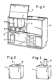
- the drink machine shown in Fig. 1 is used to mix CO2 gas-enriched and kept ready water inside the device housing 1 with a beverage concentrate within a mixing trough 2 and to dispense the resulting soft drink into a drinking vessel 3.
- three types of beverage concentrates are used in three storage containers 4 in the vending machines above the mixing trough 2 in such a way that their dispensing openings are directed downwards.
- Each of these storage containers 4 is assigned a metering chamber dispensing device 6 on a connecting piece 5 of the dispensing opening.
- This metering chamber output device contains a control slide which is equipped with a ferromagnetic armature.
- Electromagnets are arranged in the housing 1, which can generate a magnetic field in the area of the receiving gaps 7 for the metering chamber output devices 6, as a result of which the control slide within the metering chamber output device 6 is influenced.
- a metered portion of beverage concentrate is fed to the mixing trough 2, in which the mixing operation is carried out with carbonated water likewise metered into the mixing trough 2.
- the housing chamber 9, which can be covered with a flap 8 and in which the storage containers 4 are accommodated, is connected to the cooling circuit of a cooling device, so that the beverage concentrates are stored in a cooled state and are thus available for the mixed drink.
- FIG. 2 shows a storage container 4 for concentrate liquids as it is supplied from the bottler to the user.
- the dispensing opening located within the connecting piece 5 is closed by a film cover 10.
- 3 shows a storage container 4 for a beverage concentrate with a metering chamber dispensing device 6 placed on the connecting piece 5.
- the details of the storage container 4 and the metering chamber dispenser 6 for beverage concentrates can be seen from the sectional view according to FIG. 4.
- the storage container 4 consists of a film bag 11 with essentially flexible walls. These walls of the film bag 11 are connected in an annular manner to the connecting piece 5 of the storage container 4.
- This foil bag is surrounded by essentially dimensionally stable, air-permeable container walls 12 in the form of a cuboid shown in FIGS. 2 and 3.
- Cardboard is preferably used as the material for the container walls 12.
- These walls 12 form a unit and are also attached to the connecting piece 5 of the storage container 4 via the wall of the film bag 11.
- the metering chamber output unit 6 is formed by a metering chamber housing 14 which is expanded on the input side by a housing cap 13 and in which a tubular control slide 15 is arranged such that it can be displaced in height.
- the housing cap 13 is an integrated component of the connecting piece 5 of the storage container 4.
- the metering chamber housing 14 is connected to the housing cap 13 by means of short screw threads 29 distributed over the circumference and sealed with respect to this housing cap 13 by a sealing washer 16.
- the sealing ring 17 is provided for sealing to the outside, since 13 openings 18 are provided in the upper end wall of the housing cap for manufacturing reasons in the manufacture of the screw threads 25.
- the inlet-side flow opening 19 and the outlet-side flow opening 20 are arranged axially centrally in the housing cap 13 and at the lower end of the dosing chamber housing 14.
- valve closure disks 21, 22 are carried on the control slide 15, which, depending on the end position of the control slide 14, close the flow opening 19 on the input side or - as shown in FIG. 4 - the flow opening 20 on the output side alternately.
- the control slide 15 is essentially tubular and carries the inlet-side valve closure disk 21 in a cylindrical attachment 23 with openings 24. Above this valve closure disk 21, cross-shaped guide ribs 25 protrude into the inlet-side flow opening 19 as guide elements.
- the control slide 15 is equipped with a ring 26 made of ferromagnetic material which, as a submersible anchor within an electromagnet system housed in the device housing 1, is influenced by excitation of a magnetic field in such a way that the control slide 15 from the position shown, in which the flow opening 20 on the outlet side is closed, is lifted into the upper position in which the inlet opening 19 is closed.
- longitudinal guide ribs 27 are arranged so that good sliding properties between the control slide 15 and the wall of the metering chamber housing 14 are given.
- beverage concentrate present in the storage container 4 can flow into the interior of the metering chamber dispenser 6 through its inlet-side flow opening 19 due to its own gravity.
- the volume of air present in the metering chamber output device 6 flows into the storage container 4.
- This inflowing air is originally warmer than the beverage concentrate, which is normally refrigerated, results in a volume deficit after this air has cooled. Since the wall 11 of the film sack is flexible and the dimensionally stable wall does not hermetically seal this film sack, this volume deficit is already countered by a slight sagging of this film sack, so that no negative pressure occurs within the storage container 4. Temperature differences caused by intermittent cooling processes and thus volume changes within the storage container 4 are also compensated for by the flexibility of the film bag 11.
- FIG. 5 shows the same housing cap 13 as can also be seen in FIG. 4.
- Fig. 6 shows a housing cap 13 ⁇ with beveled walls 28 ⁇ , which converge conically to the flow opening 19 ⁇ . This results in a change in volume in this area and thus for the entire metering chamber dispensing device 6 compared to the use of a housing cap 13 according to FIG. Since these housing caps 13 and 13 ⁇ are integrated into the connecting piece 5 of the container 4, there is a direct reference to the nature of the beverage concentrate used. A further reduction in volume in the metering chamber dispenser 6 is possible by inserting an additional tube insert into the control piston 15.
- Predetermined breaking points 30 serve to ensure that after the metering chamber housing 14 has been removed from the housing cap, the latter is separated from its flange and is therefore no longer functional for a further connection.
Landscapes
- Engineering & Computer Science (AREA)
- Mechanical Engineering (AREA)
- Physics & Mathematics (AREA)
- Fluid Mechanics (AREA)
- General Physics & Mathematics (AREA)
- Devices For Dispensing Beverages (AREA)
- Beverage Vending Machines With Cups, And Gas Or Electricity Vending Machines (AREA)
- Sampling And Sample Adjustment (AREA)
- Package Specialized In Special Use (AREA)
- Medicines Containing Material From Animals Or Micro-Organisms (AREA)
- Accessories For Mixers (AREA)
Priority Applications (1)
| Application Number | Priority Date | Filing Date | Title |
|---|---|---|---|
| AT87109455T ATE56197T1 (de) | 1986-07-07 | 1987-07-01 | Anordnung zum bereithalten und zur dosierten abgabe von fluessigkeiten. |
Applications Claiming Priority (2)
| Application Number | Priority Date | Filing Date | Title |
|---|---|---|---|
| DE19863622777 DE3622777A1 (de) | 1986-07-07 | 1986-07-07 | Anordnung zum bereithalten und zur dosierten abgabe von fluessigkeiten |
| DE3622777 | 1986-07-07 |
Publications (2)
| Publication Number | Publication Date |
|---|---|
| EP0252420A1 true EP0252420A1 (fr) | 1988-01-13 |
| EP0252420B1 EP0252420B1 (fr) | 1990-09-05 |
Family
ID=6304576
Family Applications (1)
| Application Number | Title | Priority Date | Filing Date |
|---|---|---|---|
| EP87109455A Expired - Lifetime EP0252420B1 (fr) | 1986-07-07 | 1987-07-01 | Agencement pour la mise à la disposition et le dosage d'un liquide |
Country Status (12)
| Country | Link |
|---|---|
| US (1) | US5022558A (fr) |
| EP (1) | EP0252420B1 (fr) |
| JP (1) | JPH0637231B2 (fr) |
| KR (1) | KR960004729B1 (fr) |
| AT (1) | ATE56197T1 (fr) |
| AU (1) | AU594793B2 (fr) |
| CA (1) | CA1308078C (fr) |
| DD (1) | DD261349A5 (fr) |
| DE (2) | DE3622777A1 (fr) |
| ES (1) | ES2017965B3 (fr) |
| GR (1) | GR3000876T3 (fr) |
| ZA (1) | ZA874831B (fr) |
Cited By (6)
| Publication number | Priority date | Publication date | Assignee | Title |
|---|---|---|---|---|
| EP0358360A1 (fr) * | 1988-08-17 | 1990-03-14 | The Coca-Cola Company | Emballage amovible pour sirop |
| EP0418927A1 (fr) * | 1989-09-22 | 1991-03-27 | BOSCH-SIEMENS HAUSGERÄTE GmbH | Dispositif de distribution de doses de liquides |
| EP0445264A4 (en) * | 1989-09-22 | 1992-03-18 | The Coca-Cola Company | Dosing system and method |
| DE9303504U1 (de) * | 1993-03-10 | 1993-07-08 | Athanassiadis, Georgios, 8000 München | Dosiervorrichtung mit einem Ausgießer zur Abgabe eines bestimmten Flüssigkeitsvolumens |
| AU753149B2 (en) * | 1998-08-11 | 2002-10-10 | Technosearch Pty. Limited | Improvements in liquid discharge container side |
| US11641862B2 (en) | 2013-05-24 | 2023-05-09 | Ali S.p.A.—Carpigiani Group | Machine and method for making and dispensing liquid, semi-liquid and/or semi-solid food products |
Families Citing this family (6)
| Publication number | Priority date | Publication date | Assignee | Title |
|---|---|---|---|---|
| DK1567445T3 (da) * | 2002-11-22 | 2012-07-16 | Lesaffre & Cie | Indretning og fremgangsmåde til dosering af gærcreme |
| US7658213B1 (en) | 2005-09-29 | 2010-02-09 | Anderson Chemical Company | Fluid dispensing system |
| USD611376S1 (en) | 2009-03-12 | 2010-03-09 | Bemis Manufacturing Company | Portion of a metering device |
| DE102013212809A1 (de) | 2013-07-01 | 2015-01-08 | Brainlink Gmbh | Getränkezubereitungssystem mit Einwegbehälter |
| DE202019004089U1 (de) * | 2019-10-04 | 2021-01-11 | Stefan Schlack | Hubsystem zur Dosierung von einem Fluid aus einem Behälter und Behälter für ein Fluid |
| US11709084B2 (en) * | 2020-06-29 | 2023-07-25 | Delaware Capital Formation, Inc. | Multi-reservoir liquid dispenser and associated methods |
Citations (5)
| Publication number | Priority date | Publication date | Assignee | Title |
|---|---|---|---|---|
| US3460723A (en) * | 1966-08-24 | 1969-08-12 | Autic Dev Ltd | Liquid measures |
| US3667499A (en) * | 1970-05-04 | 1972-06-06 | Sta Rite Industries | Liquid dispensing system |
| FR2489803A1 (fr) * | 1980-09-09 | 1982-03-12 | Bosch Siemens Hausgeraete | Soupape de reglage, en particulier pour la delivrance de concentres de boissons dans les appareils automatiques distributeurs de boissons |
| FR2520471A1 (fr) * | 1982-01-26 | 1983-07-29 | Naar Raymond | Robinet verseur pour emballage souple contenant un liquide |
| AT373564B (de) * | 1980-01-24 | 1984-02-10 | Artmann Kurt | Portionierer fuer getraenke |
Family Cites Families (15)
| Publication number | Priority date | Publication date | Assignee | Title |
|---|---|---|---|---|
| DE837215C (de) * | 1950-03-05 | 1952-04-21 | Erwin Mogg | Ausgiesser fuer Fluessigkeiten zur Abgabe gemessener Mengen aus Flaschen |
| GB1168465A (en) * | 1965-11-19 | 1969-10-29 | Malpas Charles H | Improvements in Bulk Containers |
| US3666150A (en) * | 1968-11-07 | 1972-05-30 | Steli Konsult | Arrangement for delivering predetermined quantities of liquid and solid material |
| US4076147A (en) * | 1976-05-04 | 1978-02-28 | Schmit Justin M | Liquid container having a plastic film pouch and a piercing element to open the plastic film pouch |
| JPS5566938U (fr) * | 1978-10-30 | 1980-05-08 | ||
| US4375864A (en) * | 1980-07-21 | 1983-03-08 | Scholle Corporation | Container for holding and dispensing fluid |
| DE3131650C2 (de) * | 1981-03-26 | 1985-02-14 | DAGMA Deutsche Automaten- und Getränkemaschinen GmbH & Co KG, 2067 Reinfeld | Vorrichtung zum Abgeben von viskosen Konzentraten veränderlicher Viskosität in genau dosierbaren Mengen von veränderlich einstellbarem Volumen, insb. für Getränkeautomaten |
| GB2098963A (en) * | 1981-05-25 | 1982-12-01 | Douwe Egberts Tabaksfab | Method and apparatus or metering beverage concentrates |
| JPS6058804A (ja) * | 1983-09-12 | 1985-04-05 | 株式会社東芝 | 円筒状部材の製作方法 |
| US4723688A (en) * | 1983-11-03 | 1988-02-09 | Munoz Edward A | Beverage container and dispenser |
| US4709835A (en) * | 1984-03-13 | 1987-12-01 | Coca-Cola Company | Dispenser pouch for beverage syrups and concentrates |
| DE3409142A1 (de) * | 1984-03-13 | 1985-09-26 | Bosch-Siemens Hausgeräte GmbH, 7000 Stuttgart | Anordnung zur dosierten abgabe von fluessigkeiten |
| DE3412240A1 (de) * | 1984-04-02 | 1985-10-31 | William C. Catasauqua Pa. Christine | Lochdorn mit ventil fuer flexible beutel |
| DE3412545A1 (de) * | 1984-04-04 | 1985-10-17 | Gardena Kress + Kastner Gmbh, 7900 Ulm | Automatisch steuerbare ventileinrichtung |
| US4893731A (en) * | 1988-12-20 | 1990-01-16 | The Coca-Cola Company | Collapsible bag with evacuation passageway and method for making the same |
-
1986
- 1986-07-07 DE DE19863622777 patent/DE3622777A1/de not_active Ceased
-
1987
- 1987-07-01 AT AT87109455T patent/ATE56197T1/de not_active IP Right Cessation
- 1987-07-01 ES ES87109455T patent/ES2017965B3/es not_active Expired - Lifetime
- 1987-07-01 EP EP87109455A patent/EP0252420B1/fr not_active Expired - Lifetime
- 1987-07-01 DE DE8787109455T patent/DE3764733D1/de not_active Expired - Lifetime
- 1987-07-03 ZA ZA874831A patent/ZA874831B/xx unknown
- 1987-07-03 CA CA000541274A patent/CA1308078C/fr not_active Expired - Lifetime
- 1987-07-06 DD DD87304676A patent/DD261349A5/de not_active IP Right Cessation
- 1987-07-06 KR KR1019870007180A patent/KR960004729B1/ko not_active Expired - Fee Related
- 1987-07-06 AU AU75243/87A patent/AU594793B2/en not_active Ceased
- 1987-07-07 JP JP62170827A patent/JPH0637231B2/ja not_active Expired - Fee Related
-
1988
- 1988-05-03 US US07/189,827 patent/US5022558A/en not_active Expired - Fee Related
-
1990
- 1990-09-27 GR GR90400426T patent/GR3000876T3/el unknown
Patent Citations (5)
| Publication number | Priority date | Publication date | Assignee | Title |
|---|---|---|---|---|
| US3460723A (en) * | 1966-08-24 | 1969-08-12 | Autic Dev Ltd | Liquid measures |
| US3667499A (en) * | 1970-05-04 | 1972-06-06 | Sta Rite Industries | Liquid dispensing system |
| AT373564B (de) * | 1980-01-24 | 1984-02-10 | Artmann Kurt | Portionierer fuer getraenke |
| FR2489803A1 (fr) * | 1980-09-09 | 1982-03-12 | Bosch Siemens Hausgeraete | Soupape de reglage, en particulier pour la delivrance de concentres de boissons dans les appareils automatiques distributeurs de boissons |
| FR2520471A1 (fr) * | 1982-01-26 | 1983-07-29 | Naar Raymond | Robinet verseur pour emballage souple contenant un liquide |
Cited By (6)
| Publication number | Priority date | Publication date | Assignee | Title |
|---|---|---|---|---|
| EP0358360A1 (fr) * | 1988-08-17 | 1990-03-14 | The Coca-Cola Company | Emballage amovible pour sirop |
| EP0418927A1 (fr) * | 1989-09-22 | 1991-03-27 | BOSCH-SIEMENS HAUSGERÄTE GmbH | Dispositif de distribution de doses de liquides |
| EP0445264A4 (en) * | 1989-09-22 | 1992-03-18 | The Coca-Cola Company | Dosing system and method |
| DE9303504U1 (de) * | 1993-03-10 | 1993-07-08 | Athanassiadis, Georgios, 8000 München | Dosiervorrichtung mit einem Ausgießer zur Abgabe eines bestimmten Flüssigkeitsvolumens |
| AU753149B2 (en) * | 1998-08-11 | 2002-10-10 | Technosearch Pty. Limited | Improvements in liquid discharge container side |
| US11641862B2 (en) | 2013-05-24 | 2023-05-09 | Ali S.p.A.—Carpigiani Group | Machine and method for making and dispensing liquid, semi-liquid and/or semi-solid food products |
Also Published As
| Publication number | Publication date |
|---|---|
| ATE56197T1 (de) | 1990-09-15 |
| JPH0637231B2 (ja) | 1994-05-18 |
| DE3622777A1 (de) | 1988-02-04 |
| CA1308078C (fr) | 1992-09-29 |
| EP0252420B1 (fr) | 1990-09-05 |
| GR3000876T3 (en) | 1991-11-15 |
| DD261349A5 (de) | 1988-10-26 |
| US5022558A (en) | 1991-06-11 |
| ES2017965B3 (es) | 1991-03-16 |
| AU7524387A (en) | 1988-01-14 |
| AU594793B2 (en) | 1990-03-15 |
| DE3764733D1 (de) | 1990-10-11 |
| KR880001519A (ko) | 1988-04-23 |
| ZA874831B (en) | 1988-02-24 |
| KR960004729B1 (ko) | 1996-04-12 |
| JPS6382992A (ja) | 1988-04-13 |
Similar Documents
| Publication | Publication Date | Title |
|---|---|---|
| DE3346165C2 (de) | Sprühmitteleinsatz für Sprühpistolen | |
| DE69117050T2 (de) | Ventilanordnung in einem sirupspender | |
| EP0252421B1 (fr) | Distributeur de liquides avec chambre de dosage | |
| EP0252420B1 (fr) | Agencement pour la mise à la disposition et le dosage d'un liquide | |
| EP0208941B1 (fr) | Obturateur doseur | |
| EP0558954A1 (fr) | Pompe doseuse pour de produits visqueux, en particulier pâteux | |
| DE69029320T2 (de) | Dosierungsvorrichtung | |
| DE29905147U1 (de) | Über Luftdruck entleerbarer Behälter | |
| DE2544671B2 (de) | Behälter zur dosierten Abgabe von Flüssigkeiten | |
| DE69208252T2 (de) | Flasche und ventilanordnung | |
| DE2449861A1 (de) | Einrichtung zum ausschenken von qualitaetsweinen o.dgl. | |
| DE3315031C2 (de) | Verfahren und Vorrichtung zum Herstellen von Gemischen pharmazeutischer Flüssigkeiten | |
| DE8905681U1 (de) | Dosieradapter | |
| DE69700881T2 (de) | Gerät zum kühlen und/oder zum vergasen einer flüssigkeit | |
| DE69029750T2 (de) | Verfahren zum sterilen Verpacken eines flüssigen oder halb-flüssigen Produktes in einem aseptischen Behälter oder Flakon und für dieses Verfahren verwendeter Behälter oder Flakon | |
| WO1998015684A1 (fr) | Distributeur de pate | |
| DE3033873C2 (de) | Dosierventil, insbesondere zur Abgabe von Getränkekonzentraten in Getränkeautomaten | |
| DE29721534U1 (de) | Misch- und Dosierbehälter | |
| EP0106971B1 (fr) | Dispositif pour mesurer le volume de liquides, notamment du lait | |
| DE8618131U1 (de) | Anordnung zum Bereithalten und zur dosierten Abgabe von Flüssigkeiten | |
| DE19751154C2 (de) | Einrichtung zum Dosieren eines pastenförmigen Produktes | |
| DE19645532A1 (de) | Verschließfähiger, wiederverwendbarer Ausgießer für Verpackungen und Behälter in denen eine fließfähige Substanz oder Flüssigkeit enthalten ist | |
| WO2003057589A1 (fr) | Dispositif de distribution pour decharger une substance liquide, visqueuse ou pateuse contenue dans un recipient | |
| DE102018007299B4 (de) | Getränkebehälter mit mehreren Kammern | |
| EP0077910A1 (fr) | Vanne de dosage, spécialement pour débiter des liquides visqueux |
Legal Events
| Date | Code | Title | Description |
|---|---|---|---|
| PUAI | Public reference made under article 153(3) epc to a published international application that has entered the european phase |
Free format text: ORIGINAL CODE: 0009012 |
|
| AK | Designated contracting states |
Kind code of ref document: A1 Designated state(s): AT BE CH DE ES FR GB GR IT LI LU NL SE |
|
| 17P | Request for examination filed |
Effective date: 19880427 |
|
| 17Q | First examination report despatched |
Effective date: 19890410 |
|
| GRAA | (expected) grant |
Free format text: ORIGINAL CODE: 0009210 |
|
| AK | Designated contracting states |
Kind code of ref document: B1 Designated state(s): AT BE CH DE ES FR GB GR IT LI LU NL SE |
|
| REF | Corresponds to: |
Ref document number: 56197 Country of ref document: AT Date of ref document: 19900915 Kind code of ref document: T |
|
| ET | Fr: translation filed | ||
| REF | Corresponds to: |
Ref document number: 3764733 Country of ref document: DE Date of ref document: 19901011 |
|
| GBT | Gb: translation of ep patent filed (gb section 77(6)(a)/1977) | ||
| ITF | It: translation for a ep patent filed | ||
| REG | Reference to a national code |
Ref country code: GR Ref legal event code: FG4A Free format text: 3000876 |
|
| PLBE | No opposition filed within time limit |
Free format text: ORIGINAL CODE: 0009261 |
|
| STAA | Information on the status of an ep patent application or granted ep patent |
Free format text: STATUS: NO OPPOSITION FILED WITHIN TIME LIMIT |
|
| ITTA | It: last paid annual fee | ||
| 26N | No opposition filed | ||
| EPTA | Lu: last paid annual fee | ||
| EAL | Se: european patent in force in sweden |
Ref document number: 87109455.3 |
|
| PGFP | Annual fee paid to national office [announced via postgrant information from national office to epo] |
Ref country code: LU Payment date: 19951201 Year of fee payment: 9 |
|
| PGFP | Annual fee paid to national office [announced via postgrant information from national office to epo] |
Ref country code: SE Payment date: 19960614 Year of fee payment: 10 |
|
| PGFP | Annual fee paid to national office [announced via postgrant information from national office to epo] |
Ref country code: GR Payment date: 19960628 Year of fee payment: 10 |
|
| PG25 | Lapsed in a contracting state [announced via postgrant information from national office to epo] |
Ref country code: LU Free format text: LAPSE BECAUSE OF NON-PAYMENT OF DUE FEES Effective date: 19960701 |
|
| PGFP | Annual fee paid to national office [announced via postgrant information from national office to epo] |
Ref country code: ES Payment date: 19960712 Year of fee payment: 10 |
|
| PGFP | Annual fee paid to national office [announced via postgrant information from national office to epo] |
Ref country code: BE Payment date: 19960717 Year of fee payment: 10 |
|
| REG | Reference to a national code |
Ref country code: CH Ref legal event code: NV Representative=s name: RITSCHER & SEIFERT PATENTANWAELTE VSP |
|
| PG25 | Lapsed in a contracting state [announced via postgrant information from national office to epo] |
Ref country code: SE Effective date: 19970702 Ref country code: ES Free format text: THE PATENT HAS BEEN ANNULLED BY A DECISION OF A NATIONAL AUTHORITY Effective date: 19970702 |
|
| PG25 | Lapsed in a contracting state [announced via postgrant information from national office to epo] |
Ref country code: GR Free format text: LAPSE BECAUSE OF NON-PAYMENT OF DUE FEES Effective date: 19970731 Ref country code: BE Free format text: LAPSE BECAUSE OF NON-PAYMENT OF DUE FEES Effective date: 19970731 |
|
| BERE | Be: lapsed |
Owner name: COCA-COLA CY Effective date: 19970731 Owner name: BOSCH-SIEMENS HAUSGERATE G.M.B.H. Effective date: 19970731 |
|
| EUG | Se: european patent has lapsed |
Ref document number: 87109455.3 |
|
| REG | Reference to a national code |
Ref country code: ES Ref legal event code: FD2A Effective date: 20001204 |
|
| REG | Reference to a national code |
Ref country code: GB Ref legal event code: IF02 |
|
| PGFP | Annual fee paid to national office [announced via postgrant information from national office to epo] |
Ref country code: GB Payment date: 20050621 Year of fee payment: 19 |
|
| PGFP | Annual fee paid to national office [announced via postgrant information from national office to epo] |
Ref country code: AT Payment date: 20050628 Year of fee payment: 19 |
|
| PG25 | Lapsed in a contracting state [announced via postgrant information from national office to epo] |
Ref country code: IT Free format text: LAPSE BECAUSE OF NON-PAYMENT OF DUE FEES;WARNING: LAPSES OF ITALIAN PATENTS WITH EFFECTIVE DATE BEFORE 2007 MAY HAVE OCCURRED AT ANY TIME BEFORE 2007. THE CORRECT EFFECTIVE DATE MAY BE DIFFERENT FROM THE ONE RECORDED. Effective date: 20050701 |
|
| PGFP | Annual fee paid to national office [announced via postgrant information from national office to epo] |
Ref country code: FR Payment date: 20050712 Year of fee payment: 19 |
|
| PGFP | Annual fee paid to national office [announced via postgrant information from national office to epo] |
Ref country code: NL Payment date: 20050714 Year of fee payment: 19 Ref country code: DE Payment date: 20050714 Year of fee payment: 19 Ref country code: CH Payment date: 20050714 Year of fee payment: 19 |
|
| PG25 | Lapsed in a contracting state [announced via postgrant information from national office to epo] |
Ref country code: GB Free format text: LAPSE BECAUSE OF NON-PAYMENT OF DUE FEES Effective date: 20060701 Ref country code: AT Free format text: LAPSE BECAUSE OF NON-PAYMENT OF DUE FEES Effective date: 20060701 |
|
| PG25 | Lapsed in a contracting state [announced via postgrant information from national office to epo] |
Ref country code: LI Free format text: LAPSE BECAUSE OF NON-PAYMENT OF DUE FEES Effective date: 20060731 Ref country code: CH Free format text: LAPSE BECAUSE OF NON-PAYMENT OF DUE FEES Effective date: 20060731 |
|
| PG25 | Lapsed in a contracting state [announced via postgrant information from national office to epo] |
Ref country code: NL Free format text: LAPSE BECAUSE OF NON-PAYMENT OF DUE FEES Effective date: 20070201 Ref country code: DE Free format text: LAPSE BECAUSE OF NON-PAYMENT OF DUE FEES Effective date: 20070201 |
|
| REG | Reference to a national code |
Ref country code: CH Ref legal event code: PL |
|
| GBPC | Gb: european patent ceased through non-payment of renewal fee |
Effective date: 20060701 |
|
| NLV4 | Nl: lapsed or anulled due to non-payment of the annual fee |
Effective date: 20070201 |
|
| REG | Reference to a national code |
Ref country code: FR Ref legal event code: ST Effective date: 20070330 |
|
| PG25 | Lapsed in a contracting state [announced via postgrant information from national office to epo] |
Ref country code: FR Free format text: LAPSE BECAUSE OF NON-PAYMENT OF DUE FEES Effective date: 20060731 |