EP0252495A1 - Entstapelapparat für flache Produkte - Google Patents
Entstapelapparat für flache Produkte Download PDFInfo
- Publication number
- EP0252495A1 EP0252495A1 EP87109802A EP87109802A EP0252495A1 EP 0252495 A1 EP0252495 A1 EP 0252495A1 EP 87109802 A EP87109802 A EP 87109802A EP 87109802 A EP87109802 A EP 87109802A EP 0252495 A1 EP0252495 A1 EP 0252495A1
- Authority
- EP
- European Patent Office
- Prior art keywords
- objects
- jogging
- advance
- magazine
- unstacking
- Prior art date
- Legal status (The legal status is an assumption and is not a legal conclusion. Google has not performed a legal analysis and makes no representation as to the accuracy of the status listed.)
- Granted
Links
- 230000007704 transition Effects 0.000 claims abstract description 19
- 238000011144 upstream manufacturing Methods 0.000 claims abstract description 5
- 238000000926 separation method Methods 0.000 claims description 3
- 238000010408 sweeping Methods 0.000 claims 1
- 230000009471 action Effects 0.000 description 6
- 238000013519 translation Methods 0.000 description 5
- 238000012546 transfer Methods 0.000 description 3
- 238000007664 blowing Methods 0.000 description 2
- 238000001514 detection method Methods 0.000 description 2
- 230000002730 additional effect Effects 0.000 description 1
- 230000001174 ascending effect Effects 0.000 description 1
- 230000005540 biological transmission Effects 0.000 description 1
- 239000011248 coating agent Substances 0.000 description 1
- 238000000576 coating method Methods 0.000 description 1
- 230000000694 effects Effects 0.000 description 1
- 230000002349 favourable effect Effects 0.000 description 1
- 239000000463 material Substances 0.000 description 1
- 238000012986 modification Methods 0.000 description 1
- 230000004048 modification Effects 0.000 description 1
- 238000012856 packing Methods 0.000 description 1
- 229920003023 plastic Polymers 0.000 description 1
- 239000004033 plastic Substances 0.000 description 1
- 238000005498 polishing Methods 0.000 description 1
- 229920000915 polyvinyl chloride Polymers 0.000 description 1
- 239000004800 polyvinyl chloride Substances 0.000 description 1
- 230000000284 resting effect Effects 0.000 description 1
- 230000000717 retained effect Effects 0.000 description 1
- 238000007789 sealing Methods 0.000 description 1
- 238000012549 training Methods 0.000 description 1
Images


Classifications
-
- B—PERFORMING OPERATIONS; TRANSPORTING
- B65—CONVEYING; PACKING; STORING; HANDLING THIN OR FILAMENTARY MATERIAL
- B65H—HANDLING THIN OR FILAMENTARY MATERIAL, e.g. SHEETS, WEBS, CABLES
- B65H1/00—Supports or magazines for piles from which articles are to be separated
- B65H1/02—Supports or magazines for piles from which articles are to be separated adapted to support articles on edge
- B65H1/025—Supports or magazines for piles from which articles are to be separated adapted to support articles on edge with controlled positively-acting mechanical devices for advancing the pile to present the articles to the separating device
-
- B—PERFORMING OPERATIONS; TRANSPORTING
- B65—CONVEYING; PACKING; STORING; HANDLING THIN OR FILAMENTARY MATERIAL
- B65H—HANDLING THIN OR FILAMENTARY MATERIAL, e.g. SHEETS, WEBS, CABLES
- B65H2701/00—Handled material; Storage means
- B65H2701/10—Handled articles or webs
- B65H2701/19—Specific article or web
- B65H2701/1916—Envelopes and articles of mail
Definitions
- the present invention relates to the unstacking of flat objects, with a view to their removal one by one from a stack and their unitary distribution.
- These flat objects can in particular be postal folds.
- a device performing their unstacking ensures the automatic feeding of an indexing or readdressing and / or sorting machine for these folds.
- devices for unstacking flat objects essentially comprise a magazine for storing folds in a stack and an unstacking head at the end of a magazine.
- the unstacking head is equipped with suction and transfer means for the terminal fold of the stack.
- the store is, for its part, equipped with means for driving objects in a stack toward the head and means for presenting the terminal fold in front of the unstacking head.
- the unstacking head can be constituted by a suction cup animated with a tilting movement advantageously according to a back and forth stroke and a back and forth translation movement, with which a stop is associated for the final fold before removing it from the stack. It can also be constituted by a wall with suction orifices with which is associated a drum for speeding up the fold or by a belt or a drum for suction and speeding.
- the means of suitable presentation of the objects facing the unstacking head which drain the storage warehouse must meet many objectives, in particular, in the face of the constraints to be taken into account in the treatment of postal envelopes which may have very different characteristics between them .
- constraints to be taken into account we can cite in particular: - the disparity of weight and the disparity of format of the folds of a batch to be treated, - the disparity in the characteristics of the ply material, which may be made of paper or plastic for example and leading to not very smooth, porous, glazed or very smooth folds, - the disparity in constitution or consistency of the folds which may range from a simple folded sheet with sealing points, or from a simple reply card, to filled envelopes or documents in tape or wrapping and / or addressing film.
- the means for presenting the pleats in front of the unstacking head must therefore ensure, as the pleats advance towards the unstacking head, in particular, the side jogging of the pleats, which must be presented at least in the end zone of the stack aligned on one of their edges, as well as the separation of the folds from each other in this same end zone. This allows the head to make sure and correct grip of the terminal fold, but only of this single fold regardless of the characteristics of the terminal fold and those of the fold that follows it.
- These presentation means may include a lateral jogging edge on the magazine and sets of rollers mounted in the bottom of the magazine and driven in rotation to push the folds against the lateral jogging edge. They may also include means for blowing air jets on the free edges of the folds, in particular the upper edge of the folds, to separate the folds in the terminal area of the stack and / or retain the fold which follows the terminal fold to collect.
- the store can also be equipped with means giving an inclination to the folds in its terminal area so that the terminal fold is presented with the foot against the front the stop or the suction wall of the unstacking head.
- These latter means can be constituted by a set of motorized belts or a blowing ramp acting on the feet of the folds in this terminal area.
- the object of the present invention is to provide a device for unstacking objects which can have very different characteristics between them, leading by simple and very functional means. reliable with particularly improved performance.
- the present invention relates to a device for unstacking flat objects comprising a magazine receiving said objects in stack, a unstacking head at the end of the magazine, means for advancing said objects in stack on the magazine, towards the unstacking head and, in the terminal part of the magazine facing the unstacking head, a lateral edge and associated rollers for jogging objects and means for separating said objects present in front of the unstacking head, characterized in that said jogging edge comprises, from upstream to downstream on said terminal part of the magazine, a first so-called edge of transition and of straightening of the objects arranged inclined relative to the advance of said objects towards said unstacking head, and a second edge called of reference of jogging relative to said head, substantially parallel to the advance of the objects towards said head and arranged in an offset, towards the outside of the store, on said transition and straightening bank.
- a feed screw and a screw for delaying objects are interposed between the jogging rollers with which they are associated with regard to the transition and straightening bank and the reference bank of jogging.
- the transition and straightening bank has an increasing inclination from upstream to downstream, with the upper edge of its terminal part more inclined than its lower edge.
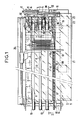
- the unstacking device comprises a magazine 1 for storing postal folds to be unstacked and a unstacking head 2 mounted at the end or before the magazine.
- the unstacking head 2 is illustrated of the suction cup type 3 mounted on an arm 4 pivoting facing the terminal fold of the stack and movable in translation laterally in front of the stack.
- a stop 5 for the foot of the terminal fold of the stack is associated with the suction cup 3.
- This type of unstacking head is as such known. Its control means has therefore simply been shown schematically in 6, it drives the suction cup in a back and forth tilting movement, indicated by the double arrow 7, for the removal of the terminal fold from the stack, the foot of which passes over the stop 5, then in a forward and backward translation movement, indicated by the double arrow 8, for the lateral transfer of the terminal fold taken.
- This unstacking head is mounted in front of the open front face of the magazine on which the simple stop 5 for the base fold end of the stack is defined.
- Tray 1 is of the type with manual loading of a stack of folds; it is open at least on its upper side which is not referenced, advantageously has its bottom 9 inclined to the horizontal, with an ascending slope from back to front and has a retaining pallet 10 at the rear of the stack. He receives an unorganized pile of pleats to be deposed resting on edge on its bottom and retained by the rear pallet. It has an internal lateral flank 11 retaining, if necessary, the stack of folds during loading.
- This store is organized, according to its length considered from the rear of the store, into three zones denoted Z1, Z2, Z3.
- the zone Z1 corresponds to the major part of its length, it constitutes a zone known as advance of the folds in stack towards the unstacking head.
- the zone Z zone of short length is the terminal zone in front of the unstacking head, it constitutes a so-called unstacking waiting zone.
- the zone Z2 is the intermediate zone it is called the transition and straightening zone of the folds; it receives the folds as they appear from the zone Z1 and simultaneously ensures their jogging and their straightening during their passage towards the waiting zone for unstacking Z3 for their presentation as favorable as possible for unstacking in front of the unstacking head .
- this store is differently equipped according to its areas.
- drive means ensure the advance of the stack of folds as they have been loaded.
- These means consist of a set of endless conveyor belts 12 mounted in the bottom of the store, coming in slight projection above the bottom. These belts 12 are stretched between drive pulleys 13 carried by a drive shaft 14 at the rear of the magazine and return pulleys 15 carried by a return shaft 16, substantially at the end part of the zone of Z1 advances.
- An endless drive chain 17 runs along the length of zones Z1, Z2 and Z3. It is stretched between a pinion 18 carried by the rear shaft 14 and a deflection roller 19 mounted at the end of the magazine, at the front of the shaft 16. It is coupled to a motor 20 by a pinion 21. It transmits the motorization with the belts 12, by the shaft 14 and the hens 13, for advancing the folds in the stack, as they were loaded. This advance is indicated by the arrow F.
- the retaining pallet 10 at the rear of the stack is also coupled to the chain 17, for its advance in synchronism with the stack of plies.
- This pallet is slidably mounted along a lateral guide 25 on the magazine and has a finger or lug 26 for hooking between the links of the chain 17.
- This protruding finger or lug at the bottom of the pallet ensures the advance of the pallet according to arrow F practically up to the stop 5, at which the chain, fleeing on its idler roller 19 under the magazine, escapes it.
- the return of the pallet to the rear of the magazine for a new loading of the magazine is ensured manually with a slight pivoting of the pallet avoiding during this rear return the catch of his finger on the chain while stopped.
- a lateral jogging edge 30 gives the jogging reference for the plies relative to the unstacking head.
- another lateral jogging edge 31 ensures the transition between the internal lateral edge 11 of the magazine and the reference lateral edge 30. This edge is profiled as will be seen below to also ensure the straightening of the folds abutted against it and appearing too inclined, in order to ensure their optimal presentation in front of the unstacking head as soon as they pass through the zone Z3 waiting for unstacking.
- This edge 31 is fixed to the internal lateral flank 11 of the magazine; to this end, it has a vertical end portion fixed to the internal lateral flank 11 in the zone Z1 and then is inclined, with respect to the advance of the folds according to arrow F, essentially along the zone Z2. Its end in zone Z2 is offset from the edge 30 of the jogging reference of zone Z3, which is more external to the magazine and extends behind the bank 31 in zone Z2.
- the jogging reference edge 30 is vertical.
- edges 31 and 30 are associated with two jogging rollers 35 and 36 and two screws 37 and 38 with helical threads with reverse pitch from one screw to the other and called advance and delay screws folds.
- rollers and screws are mounted at the end of the magazine, with the screws interposed between the rollers. They are of axis parallel in advance according to the arrow F of the folds; they extend the bottom 9 of the magazine and the means for advancing the folds 12 which equip the bottom 9, up to the stop 5 while being in slight relief above the level of the bottom 9.
- a bottom front plate 39 is associated with the rollers and screws 35, 36 and 37, 38; this cut plate defines slots inserted in the intervals between rollers and screws, and extends the bottom 9.
- the threaded screw 37 following the roller 35 in the direction transverse to the magazine, is the screw for advancing the folds. It is threaded over the zone Z2, ie substantially over two thirds of its length; its terminal portion belonging to zone Z3 is smooth and at its periphery substantially at the level of that of the roller 37.
- This advance screw 37 is disposed substantially opposite the unstacking head 2.
- the other threaded screw 38 following the roller 35 and the feed screw 37, which is the fold delay screw, is only threaded in its end position belonging to zone Z3 and at the end of zone Z2. Its main portion, belonging to the zone Z2 and corresponding substantially to thirds of its length, is smooth and has its periphery which comes at the level of the jogging rollers and contributes to jogging.
- the second jogging roller 36 extends between the chain 17 and the delay screw 38, substantially on the external side of the magazine.
- the two jogging rollers 35 and 36 and the two advance and delay screws 37 and 38 are rotated from the same geared motor 40.
- a flat belt 41 and pulleys 42 with which tensioners 43 are associated ensure their training.
- the speed of rotation of the rollers and screws is chosen to obtain a linear speed of advance in the zone Z2 greater than that due to the straps in the zone Z1 and a linear speed of delay in the zone Z3 of the same order of magnitude than that in zone Z1.
- a photoelectric cell 45 and an associated lamp 46 ensure the detection of folds in the unstacking waiting zone Z3.
- the lamp 46 is mounted above the side jogging edge 30 of the zone Z3 practically at the end of the edge 31, the photoelectric cell is mounted on the opposite side, substantially at the end of the stop 5; they define an axis of detection of the folds crossing obliquely the zone Z3.
- This cell controls, when the beam emitted by the lamp is interrupted and then not picked up, in particular when there are folds in the zone Z3, the stopping of the motor 20 ensuring the advance of the folds and in the contrary case , its start-up. It also controls the stopping of this engine when the magazine is completely empty after a destacking operation, under these conditions the pallet having arrived in the zone Z3 and coming to interrupt the beam of the lamp 46.
- a second stop 50 in front of the stop 5, defines with the latter a chute for receiving the fold gripped by the suction cup 3 and for guiding the fold during its transfer into translation by suction cup.
- the fold entered which is transferred in translation along the arrow 8 between the stops 5 and 50, is then taken care of by a belt system generally designated by the reference 51, for its ejection and possible treatment.
- FIGS. 4 and 5 there is illustrated separately and on a larger scale the bank of transmission and straightening 31, seen from the front and from above.
- this bank 31 first of all has a vertical end tab 53 for attachment to the internal lateral flank 11 of the magazine.
- Horizontal buttonholes 54 provided on this tab 53 allow adjustment of the positioning of the edge at the end of the internal lateral flank of the magazine.
- the edge 31 proper is understood beyond the latching lug 53, it is inclined on the latching lug to extend towards the outside of the store and also widens over the height of the store.
- This inclined part has a first flat portion 55 adjoining the vertical hooking tab and a second curved portion 56 substantially along a frustoconical surface.
- the flat portion 55 forms with the hooking lug 53 a bias edge 58 after folding, on the face of the bank 31 facing the interior of the store.
- the folding angle, noted A is advantageously chosen to be of the order of 20 degrees, it gives the inclination of the edge relative to the advance of the folds according to arrow F.
- the lower edge of this planar portion 55 is parallel at the bottom of the magazine, its upper edge 59 is inclined to flare the bank towards the front of the magazine.
- the curved portion 56 extends the planar portion 55, without any really visible transition therefrom. This transition is shown diagrammatically by the dotted line 57.
- the portion 56 results from preforming, then from polishing with the portion 55.
- the radius of curvature of its lower edge is substantially double that of its upper edge, to accentuate the inclination, towards the outside of the store, of the upper part of this portion relative to that of its lower part and thus reduce height the effort, even small, of sliding of the folds on this terminal portion of the bank 31.
- the radii of curvature R1 and R2 of its lower and upper edges tangent to the line 57 have been noted.
- the internal face of the store of this bank 31 is covered with a coating or with a non-stick film not shown, such as a polyvinyl chloride film.
- the advance of the folds as they have been loaded is ensured according to the arrow F by the belts 12.
- these are stressed by the action of the slight transverse force exerted on their foot, by friction on the jogging rollers, for jogging the folds against the inclined flat portion of the bank 31, and simultaneously by the advancing action exerted on their foot by the advancing screw.
- the jogging rollers and the smooth portion of the advance screw hold the folds against the jogging reference edge.
- the delay screw 31 continues its action on the folds; it gives the terminal fold a biased positioning of a few degrees relative to the stop 5, to avoid any possible packing of folds in this unstacking waiting zone Z3 and a possible thrust which can lead to bonding of the terminal fold against the suction cup in rest position.
Landscapes
- Engineering & Computer Science (AREA)
- Mechanical Engineering (AREA)
- Sheets, Magazines, And Separation Thereof (AREA)
- Feeding Of Articles By Means Other Than Belts Or Rollers (AREA)
Applications Claiming Priority (2)
| Application Number | Priority Date | Filing Date | Title |
|---|---|---|---|
| FR8610007A FR2601342B1 (fr) | 1986-07-09 | 1986-07-09 | Dispositif de depilage d'objets plats |
| FR8610007 | 1986-07-09 |
Publications (2)
| Publication Number | Publication Date |
|---|---|
| EP0252495A1 true EP0252495A1 (de) | 1988-01-13 |
| EP0252495B1 EP0252495B1 (de) | 1990-10-10 |
Family
ID=9337262
Family Applications (1)
| Application Number | Title | Priority Date | Filing Date |
|---|---|---|---|
| EP87109802A Expired - Lifetime EP0252495B1 (de) | 1986-07-09 | 1987-07-07 | Entstapelapparat für flache Produkte |
Country Status (5)
| Country | Link |
|---|---|
| US (1) | US4757985A (de) |
| EP (1) | EP0252495B1 (de) |
| CA (1) | CA1289155C (de) |
| DE (1) | DE3765474D1 (de) |
| FR (1) | FR2601342B1 (de) |
Families Citing this family (32)
| Publication number | Priority date | Publication date | Assignee | Title |
|---|---|---|---|---|
| US5219432A (en) * | 1987-06-18 | 1993-06-15 | Compagnie Generale D'automatisme Cga Hgs | Device for unstacking flat objects |
| US4891088A (en) * | 1987-10-16 | 1990-01-02 | Bell & Howell Company | Document forwarding system |
| US4928946A (en) * | 1988-05-25 | 1990-05-29 | Bell & Howell Company | Vertical feed mechanism for documents |
| US5225665A (en) * | 1990-07-27 | 1993-07-06 | General Signal Corporation | Ticket originating and processing device for transit vehicle |
| US5092575A (en) * | 1990-09-05 | 1992-03-03 | Pitney Bowes Inc. | Portable apparatus for supporting sheets |
| US5116039A (en) * | 1990-09-05 | 1992-05-26 | Pitney Bowes Inc. | Apparatus for feeding sheets from a stack thereof |
| US5197590A (en) * | 1991-04-30 | 1993-03-30 | Prim Hall Enterprises Inc. | Hopper loader |
| US5297785A (en) * | 1992-08-28 | 1994-03-29 | Bell & Howell Phillipsburg Company | Pre-feed shingling device for flat-article feeder |
| FR2700529B1 (fr) * | 1993-01-19 | 1995-02-24 | Cga Hbs | Machine de traitement de courrier ayant un retaqueur mécanique à rouleaux. |
| DE19547292A1 (de) * | 1995-12-19 | 1997-06-26 | Aeg Electrocom Gmbh | Vorrichtung und Verfahren zum Zwischenstapeln von Sendungen |
| CA2246655A1 (en) * | 1996-02-21 | 1997-08-28 | Boewe, Bell & Howell Postal Systems Company | Magazine apparatus and method for loading documents |
| US5829742A (en) * | 1996-02-21 | 1998-11-03 | Bell & Howell Postal Systems Inc. | In-feed magazine apparatus and method for loading documents |
| US5934866A (en) * | 1997-01-30 | 1999-08-10 | Gelco International L.L.C. | Plate feeder apparatus |
| US6024533A (en) * | 1998-09-30 | 2000-02-15 | Gelco International L.L.C. | Battery plate feeding and handling apparatus |
| US6315286B1 (en) | 1999-12-07 | 2001-11-13 | Pitney Bowes Inc. | Jogger system for a mixed mail cancellation feeder |
| US6270070B1 (en) | 1999-12-21 | 2001-08-07 | Pitney Bowes Inc. | Apparatus and method for detecting and correcting high stack forces |
| US6217020B1 (en) | 1999-12-21 | 2001-04-17 | Pitney Bowes Inc. | Method and apparatus for detecting proper mailpiece position for feeding |
| US6354587B1 (en) * | 2000-05-24 | 2002-03-12 | Lockheed Corp | Follower mechanism for flat article handling system |
| US20050077217A1 (en) * | 2003-03-28 | 2005-04-14 | Hillerich Thomas A. | Carrier for mail and/or the like thin objects |
| US7195236B2 (en) * | 2003-03-28 | 2007-03-27 | Northrop Grumman Corporation | Automated induction systems and methods for mail and/or other objects |
| US20060000752A1 (en) * | 2003-03-28 | 2006-01-05 | Northrop Grumman Corporation | Stack correction system and method |
| US20040245714A1 (en) * | 2003-05-13 | 2004-12-09 | Ryan Patrick J. | Enhanced object-feeder pre-processing system |
| DE10360692A1 (de) * | 2003-12-19 | 2005-07-14 | Böwe Bell + Howell GmbH | Verfahren und Vorrichtung zur Vereinzelung von Briefen |
| US7249762B1 (en) * | 2004-05-27 | 2007-07-31 | Unisys Corporation | System for feeding and transporting documents |
| US20060099065A1 (en) * | 2004-08-27 | 2006-05-11 | Northrop Grumman Corporation | Preparation operator flex-station for carrier preparation |
| US7467792B2 (en) * | 2004-09-24 | 2008-12-23 | Northrop Grumman Corporation | Anti-toppling device for mail with retractable protrusion |
| US7553119B2 (en) * | 2006-02-24 | 2009-06-30 | Northrop Grumman Systems Corporation | Mail tray unloader with shuttle transfer through system comprising tilting |
| JP5274999B2 (ja) * | 2007-12-12 | 2013-08-28 | 日立オムロンターミナルソリューションズ株式会社 | 紙幣取扱装置 |
| US7766171B2 (en) | 2008-02-28 | 2010-08-03 | Northrop Grumman Systems Corporation | Rigid storage tray for flat and letter mail |
| DE102013212423A1 (de) * | 2013-06-27 | 2014-12-31 | Siemens Aktiengesellschaft | Vorrichtung und Verfahren zum Entschichten und Fördern von in Stapeln angeordneten Gegenständen |
| US10087024B2 (en) * | 2015-02-20 | 2018-10-02 | DMT Solutions Global Corp. | Envelope feeder with selective suction cup assist |
| FR3054796B1 (fr) * | 2016-08-08 | 2018-07-13 | Solystic | Machine de tri postal avec un tasseur de sortie de tri muni d'une roue a helice a demontage rapide |
Citations (5)
| Publication number | Priority date | Publication date | Assignee | Title |
|---|---|---|---|---|
| US2191586A (en) * | 1938-04-23 | 1940-02-27 | Johnson Automatic Sealer Co Lt | Carton feeding mechanism |
| US3966193A (en) * | 1975-03-12 | 1976-06-29 | Pitney-Bowes, Inc. | Mail handling stacking and feeding apparatus |
| US3995851A (en) * | 1975-10-02 | 1976-12-07 | Burroughs Corporation | Document jogger transport |
| US4183517A (en) * | 1977-12-27 | 1980-01-15 | Harris Corporation | Apparatus and method for delivering signatures to a gatherer |
| US4295645A (en) * | 1980-02-19 | 1981-10-20 | Burroughs Corporation | Document hopper with eccentric floor cylinders and a front auger |
Family Cites Families (3)
| Publication number | Priority date | Publication date | Assignee | Title |
|---|---|---|---|---|
| US3035834A (en) * | 1959-03-02 | 1962-05-22 | Burroughs Corp | Sheet stack advance mechanism |
| US4299379A (en) * | 1978-02-21 | 1981-11-10 | E-Systems, Inc. | Moving carriage buffer/feeder |
| US4621798A (en) * | 1984-05-11 | 1986-11-11 | Bell & Howell Company | Envelope feeding mechanism for mail sorting machines |
-
1986
- 1986-07-09 FR FR8610007A patent/FR2601342B1/fr not_active Expired
-
1987
- 1987-07-07 DE DE8787109802T patent/DE3765474D1/de not_active Expired - Fee Related
- 1987-07-07 EP EP87109802A patent/EP0252495B1/de not_active Expired - Lifetime
- 1987-07-08 CA CA000541631A patent/CA1289155C/fr not_active Expired - Fee Related
- 1987-07-08 US US07/071,125 patent/US4757985A/en not_active Expired - Fee Related
Patent Citations (5)
| Publication number | Priority date | Publication date | Assignee | Title |
|---|---|---|---|---|
| US2191586A (en) * | 1938-04-23 | 1940-02-27 | Johnson Automatic Sealer Co Lt | Carton feeding mechanism |
| US3966193A (en) * | 1975-03-12 | 1976-06-29 | Pitney-Bowes, Inc. | Mail handling stacking and feeding apparatus |
| US3995851A (en) * | 1975-10-02 | 1976-12-07 | Burroughs Corporation | Document jogger transport |
| US4183517A (en) * | 1977-12-27 | 1980-01-15 | Harris Corporation | Apparatus and method for delivering signatures to a gatherer |
| US4295645A (en) * | 1980-02-19 | 1981-10-20 | Burroughs Corporation | Document hopper with eccentric floor cylinders and a front auger |
Also Published As
| Publication number | Publication date |
|---|---|
| FR2601342B1 (fr) | 1988-09-23 |
| DE3765474D1 (de) | 1990-11-15 |
| CA1289155C (fr) | 1991-09-17 |
| FR2601342A1 (fr) | 1988-01-15 |
| EP0252495B1 (de) | 1990-10-10 |
| US4757985A (en) | 1988-07-19 |
Similar Documents
| Publication | Publication Date | Title |
|---|---|---|
| EP0252495B1 (de) | Entstapelapparat für flache Produkte | |
| EP0191351B1 (de) | Vorrichtung zum Trennen von flachen Gegenständen mit unterschiedlichen Abmessungen | |
| CA2027892C (fr) | Magasin de stockage et d'alimentation d'articles plats a depiler | |
| EP0122817B1 (de) | Verfahren und Vorrichtung zum automatischen Beschicken einer Maschine zur Behandlung von flachen Gegenständen | |
| EP0195348A1 (de) | Entstapler für flache Gegenstände | |
| CA2092243C (fr) | Dispositif d'amenage d'une pile d'objets plats sur chant vers une tete de depilage de systeme de tri automatique et procede de mise en oeuvre dece dispositif | |
| EP0589789A1 (de) | Vorrichtung zum Entstapeln von flachen Gegenständen mit Vorrichtung zum Ausrichten der Vorderkante | |
| EP0507662A1 (de) | Vorrichtung zum Stapeln von flachen Gegenständen, wie Postbriefumschläge | |
| FR2713993A1 (fr) | Appareil destiné à commander la position d'une enveloppe dans une machine à insérer. | |
| EP0244308B1 (de) | Maschine zum Aufnehmen und Stapeln von geschnittenen Bögen | |
| EP2277810A1 (de) | Versorgungsvorrichtung mit verbesserter Adhärenz | |
| EP0333596A1 (de) | Vorrichtung zum Stapeln von flachen Gegenständen, wie Briefe | |
| EP0087340B1 (de) | Vorrichtung zum Ablenken und Stapeln von Umschlägen | |
| WO1997018957A1 (fr) | Systeme de depilage et d'ouverture d'enveloppes | |
| US5188504A (en) | Envelope opener and load separator | |
| FR2598975A1 (fr) | Dispositif d'ouverture d'enveloppes. | |
| FR2726506A1 (fr) | Trieuse a agrafage incorpore | |
| EP0280619A2 (de) | Vorrichtung zum Zusammensetzen von Zuschnitten, insbesondere im Hinblick auf die Herstellung von Verpackungen | |
| FR2601347A1 (fr) | Dispositif pour placer debout des elements en forme de feuille | |
| EP0316247A2 (de) | Maschine zur selbsttätigen Abgabe von Schalen | |
| CA2132800C (fr) | Magasin d'approvisionnement en objets plats et dispositif de depilage d'objets plats equipe de ce magasin | |
| EP1120288A1 (de) | Vorrichtung zum optimierten Verschliessen von Briefklappen | |
| EP1524224B1 (de) | Schneidvorrichtung für blattförmige Rohlinge | |
| FR2686868A1 (fr) | Dispositif de rigidification et d'ejection de feuillets de faible epaisseur. | |
| FR2721297A1 (fr) | Dispositif de dépilage d'objets minces empilés. |
Legal Events
| Date | Code | Title | Description |
|---|---|---|---|
| PUAI | Public reference made under article 153(3) epc to a published international application that has entered the european phase |
Free format text: ORIGINAL CODE: 0009012 |
|
| AK | Designated contracting states |
Kind code of ref document: A1 Designated state(s): DE FR GB |
|
| 17P | Request for examination filed |
Effective date: 19880711 |
|
| 17Q | First examination report despatched |
Effective date: 19890825 |
|
| GRAA | (expected) grant |
Free format text: ORIGINAL CODE: 0009210 |
|
| AK | Designated contracting states |
Kind code of ref document: B1 Designated state(s): DE FR GB |
|
| REF | Corresponds to: |
Ref document number: 3765474 Country of ref document: DE Date of ref document: 19901115 |
|
| GBT | Gb: translation of ep patent filed (gb section 77(6)(a)/1977) | ||
| PLBE | No opposition filed within time limit |
Free format text: ORIGINAL CODE: 0009261 |
|
| STAA | Information on the status of an ep patent application or granted ep patent |
Free format text: STATUS: NO OPPOSITION FILED WITHIN TIME LIMIT |
|
| 26N | No opposition filed | ||
| PGFP | Annual fee paid to national office [announced via postgrant information from national office to epo] |
Ref country code: FR Payment date: 19920527 Year of fee payment: 6 |
|
| PGFP | Annual fee paid to national office [announced via postgrant information from national office to epo] |
Ref country code: DE Payment date: 19920615 Year of fee payment: 6 |
|
| PGFP | Annual fee paid to national office [announced via postgrant information from national office to epo] |
Ref country code: GB Payment date: 19920625 Year of fee payment: 6 |
|
| PG25 | Lapsed in a contracting state [announced via postgrant information from national office to epo] |
Ref country code: GB Effective date: 19930707 |
|
| GBPC | Gb: european patent ceased through non-payment of renewal fee |
Effective date: 19930707 |
|
| PG25 | Lapsed in a contracting state [announced via postgrant information from national office to epo] |
Ref country code: FR Effective date: 19940331 |
|
| PG25 | Lapsed in a contracting state [announced via postgrant information from national office to epo] |
Ref country code: DE Effective date: 19940401 |
|
| REG | Reference to a national code |
Ref country code: FR Ref legal event code: ST |