EP0252715A2 - Pompe ou moteur à fluide préssurisé et à piston radial - Google Patents
Pompe ou moteur à fluide préssurisé et à piston radial Download PDFInfo
- Publication number
- EP0252715A2 EP0252715A2 EP87305988A EP87305988A EP0252715A2 EP 0252715 A2 EP0252715 A2 EP 0252715A2 EP 87305988 A EP87305988 A EP 87305988A EP 87305988 A EP87305988 A EP 87305988A EP 0252715 A2 EP0252715 A2 EP 0252715A2
- Authority
- EP
- European Patent Office
- Prior art keywords
- main body
- plane
- casing
- taper
- cover
- Prior art date
- Legal status (The legal status is an assumption and is not a legal conclusion. Google has not performed a legal analysis and makes no representation as to the accuracy of the status listed.)
- Granted
Links
Images




Classifications
-
- F—MECHANICAL ENGINEERING; LIGHTING; HEATING; WEAPONS; BLASTING
- F15—FLUID-PRESSURE ACTUATORS; HYDRAULICS OR PNEUMATICS IN GENERAL
- F15B—SYSTEMS ACTING BY MEANS OF FLUIDS IN GENERAL; FLUID-PRESSURE ACTUATORS, e.g. SERVOMOTORS; DETAILS OF FLUID-PRESSURE SYSTEMS, NOT OTHERWISE PROVIDED FOR
- F15B11/00—Servomotor systems without provision for follow-up action; Circuits therefor
- F15B11/02—Systems essentially incorporating special features for controlling the speed or actuating force of an output member
-
- F—MECHANICAL ENGINEERING; LIGHTING; HEATING; WEAPONS; BLASTING
- F01—MACHINES OR ENGINES IN GENERAL; ENGINE PLANTS IN GENERAL; STEAM ENGINES
- F01B—MACHINES OR ENGINES, IN GENERAL OR OF POSITIVE-DISPLACEMENT TYPE, e.g. STEAM ENGINES
- F01B13/00—Reciprocating-piston machines or engines with rotating cylinders in order to obtain the reciprocating-piston motion
- F01B13/04—Reciprocating-piston machines or engines with rotating cylinders in order to obtain the reciprocating-piston motion with more than one cylinder
- F01B13/06—Reciprocating-piston machines or engines with rotating cylinders in order to obtain the reciprocating-piston motion with more than one cylinder in star arrangement
- F01B13/061—Reciprocating-piston machines or engines with rotating cylinders in order to obtain the reciprocating-piston motion with more than one cylinder in star arrangement the connection of the pistons with the actuated or actuating element being at the outer ends of the cylinders
Definitions
- This invention to a fluid energy converter used as fluid pump or fluid motor.
- a rear cover is fitted to the opening end of its casing, and a cylinder barrel disposed within said casing is supported on this rear cover by way of an eccentric pintle.
- a large misaligning force in the radial direction may occur between said casing main body and rear cover. What is more, smooth operation is spoiled unless the casing and the rear cover are coupled in a correctly positioned state.
- a spigot was provided between the casing main body and the rear cover, and a flange coupling part was disposed at its outer side, and the two parts are accurately coupled together by placing a bolt or other fixing means in this flange coupling part.
- This invention is therefore intended to solve these problems securely and easily.
- This invention in order to achieve said object, is characterized by the screw-fitting structure by the helical taper plane provided in the coupling part of the casing main body and cover.
- the fluid energy transducer of this invention is composed by helically forming a taper plane at an angle of 45° or less with respect to the axial center on the inner circumference or outer circumference of the opening end part of the casing main body, forming a helical taper plane at a same angle as said taper plane on the cover and a stopping plane to stop the opening end of the casing main body, and screwing the taper plane forming part of the casing main body up to the position where the opening end is stopped on said stopping plane.
- the casing main body and cover may be coupled by a simple operation similar to screw fitting. Still more, by fitting the opening end of the casing main body on the stopping plane of the cover, the positioning of the two parts in the axial direction may be accurately achieved.
- the casing main body and cover can be securely and accurately joined together.
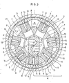
- Fig. 1 to Fig. 5 relate to an embodiment of this invention, in which Fig. 1 is a longitudinal sectional view, Fig. 2 is a sectional view of II-II in Fig. 1, Fig. 3 is a lateral sectional view, Fig. 4 is a partial sectional view showing a magnified view of arrow IV part in Fig. 1, and Fig. 5 is an explanatory diagram showing the mode of use.
- Fig. 6 is an explantory diagram corresponding to Fig. 5 to indicate a prior art.
- the fluid energy converter shown in Fig. 1 to Fig. 3 has a structure as disclosed in the Japanese Laid-open Patent No. 58-77179. That is, this energy converter is composed of casing 1, a torque ring 4 possessing inner flat planes 3 respectively at the inside of the positions corresponding to plural first static pressure bearings 2 rotatably fitted relatively through said static pressure bearings 2 provided on the inner circumference la of this casing, plural pistons 6 being disposed inside of this torque ring 4 with its end fitted to said inner flat planes 3 through second static pressure bearings 5, a cylinder barrel 8 holding these pistons 6 in a slidable manner and forming a free space 7 for entry and discharge of fluid in these pistons 6, a pintle 9 for rotatable supporting said cylinder barrel 8 being disposed reciprocatably in the direction orthogonal to the axial center m of said casing 1 and torque ring 4, and fluid passages 11, 12 forming a pair to communicate with the space 7 of which volume is increased and with the space 7
- the fluid to fill up said spaces 7 is led into corresponding first and second static pressure bearings by way of the fluid passages 13, 14, and it is designed to develop a couple in the torque ring 4 around the rotation axial center m by the static pressure of the fluid led into the first static pressure bearing 2 and the static pressure of the fluid led into the second static pressure bearing 5.
- the casing 1 of such fluid energy converter is composed of a casing main body 21, and a rear cover 22 fitted to the opening end of this casing main body.
- the casing main body 21 is shaped like a cup to accommodate said torque ring 4, piston 6, and cylinder barrel 8, and its rear end is opened.
- a taper plane 23 is formed in the inner circumference of the opening end 21a of this casing main body 1.
- This taper plane has an angle ⁇ of 45° or less with repsect to the axial center m of this casing main body 1, with a specified width, and it is formed helically. That is, this taper plane 23 has a helical taper surface.
- a steep slope 24 of a specified width is formed between the top edge and bottom edge of this taper plane 23.
- the rear cover 22 is shaped like a disc to support the cylinder barrel 8 by way of the pintle 9, and it has a trapezoidal groove 22a in which the base end part 9a of the pintle 9 is fitted slidable.
- This rear cover 22 has an annular stopping plane 25 for stopping the opening end 21b of the casing main body 21, and a circular buging part 26 formed inside this stopping plane 25.
- This taper plane 27 has the same angle ⁇ with respect to the axial center m of the casing main body 21, with a specified width, and is formed helically in the same pitch as that of said taper plane 23.
- the taper plane 23 forming area of the casing 21 is tightened by screwing up to the positiontion where the opening end 21 is fixed on the stopping plane 25.
- the casing main body 21 can be positioned by abutting its opening end 21b against the stopping plane 25 of the rear cover 22, the repeatability of positioning in the axial direction will be also excellent.
- first and second fluid passages 11, 12 of one fluid energy converter I1, and the first and second fluid passages (not shown) of the other fluid energy converter I2 are connected with each other by way of first and second communicating routes 28, 29 formed at both sides of the rear cover 22, thereby composing a liquid pressure transmission of so-called HST type.
- first and second communicating routes 28, 29 formed at both sides of the rear cover 22, thereby composing a liquid pressure transmission of so-called HST type.
- the casing main bodies a and rear covers b of the fluid energy coverters II1, II2 are positioned by the spigots c, and by placing bolts e into the flange connection parts d provided outside, the casing main bodies a and rear covers b are joined, which means it is difficult to reduce the spacing distance Lb between the two casing main bodies a.
- the outside diameter can be notably reduced, and the entire equipment may be reduced in size and weight.
- the taper plane is formed inside the opening end of the casing main body, which is not, however, limitative.
- a spiral taper plane may be formed outside the casing main body, and a taper plane fitting with this taper plane may be formed inside the dent part provided in the rear cover.
- the internal structure of the fluid energy transducer is not limited to the above consitution, and it may be also possible, for example, to apply an ordinary radial piston type pump/motor.
- This invention having such organization, is intended to position and joint the casing main body and cover accurately, without requirement of high precision in machining or difficulty in assembing work, and if a large misaligning force in the radial direction is applied between the casing main body and cover, its posi- tioning state will not be spoiled, so that it is possible to present an excellent fluid energy converter reduced in both size and weight by spontaneously reducing the maximum outside diameter of the entire equipment.
Landscapes
- Engineering & Computer Science (AREA)
- Mechanical Engineering (AREA)
- General Engineering & Computer Science (AREA)
- Physics & Mathematics (AREA)
- Fluid Mechanics (AREA)
- Hydraulic Motors (AREA)
- Reciprocating Pumps (AREA)
- Actuator (AREA)
Applications Claiming Priority (2)
| Application Number | Priority Date | Filing Date | Title |
|---|---|---|---|
| JP1986104403U JPH073023Y2 (ja) | 1986-07-07 | 1986-07-07 | 流体エネルギ変換機 |
| JP104403/86 | 1986-07-07 |
Publications (3)
| Publication Number | Publication Date |
|---|---|
| EP0252715A2 true EP0252715A2 (fr) | 1988-01-13 |
| EP0252715A3 EP0252715A3 (en) | 1989-02-22 |
| EP0252715B1 EP0252715B1 (fr) | 1992-03-11 |
Family
ID=14379752
Family Applications (1)
| Application Number | Title | Priority Date | Filing Date |
|---|---|---|---|
| EP87305988A Expired - Lifetime EP0252715B1 (fr) | 1986-07-07 | 1987-07-07 | Pompe ou moteur à fluide préssurisé et à piston radial |
Country Status (5)
| Country | Link |
|---|---|
| EP (1) | EP0252715B1 (fr) |
| JP (1) | JPH073023Y2 (fr) |
| KR (1) | KR910007262B1 (fr) |
| CN (1) | CN1012211B (fr) |
| DE (1) | DE3777262D1 (fr) |
Families Citing this family (1)
| Publication number | Priority date | Publication date | Assignee | Title |
|---|---|---|---|---|
| JP3719990B2 (ja) | 2002-02-15 | 2005-11-24 | 株式会社デンソー | 圧縮機 |
Family Cites Families (4)
| Publication number | Priority date | Publication date | Assignee | Title |
|---|---|---|---|---|
| US2620736A (en) * | 1945-12-28 | 1952-12-09 | John W Overbeke | Fluid handling mechanism |
| DE1608626B1 (de) * | 1963-12-10 | 1969-09-11 | Sigri Elektrographit Gmbh | Gesicherte Schraubverbindung von zwei Kohlenkoerpern |
| CA1051329A (fr) * | 1975-10-08 | 1979-03-27 | Horace D. Holmes | Filetage verrouillant |
| US4307816A (en) * | 1980-03-06 | 1981-12-29 | Hersey Products, Inc. | Meter closure |
-
1986
- 1986-07-07 JP JP1986104403U patent/JPH073023Y2/ja not_active Expired - Lifetime
-
1987
- 1987-07-06 CN CN87104630A patent/CN1012211B/zh not_active Expired
- 1987-07-07 DE DE8787305988T patent/DE3777262D1/de not_active Expired - Fee Related
- 1987-07-07 KR KR1019870007211A patent/KR910007262B1/ko not_active Expired
- 1987-07-07 EP EP87305988A patent/EP0252715B1/fr not_active Expired - Lifetime
Also Published As
| Publication number | Publication date |
|---|---|
| JPS6310271U (fr) | 1988-01-23 |
| KR910007262B1 (ko) | 1991-09-24 |
| DE3777262D1 (de) | 1992-04-16 |
| EP0252715B1 (fr) | 1992-03-11 |
| CN87104630A (zh) | 1988-02-03 |
| KR880001937A (ko) | 1988-04-28 |
| CN1012211B (zh) | 1991-03-27 |
| JPH073023Y2 (ja) | 1995-01-30 |
| EP0252715A3 (en) | 1989-02-22 |
Similar Documents
| Publication | Publication Date | Title |
|---|---|---|
| JPH0143514Y2 (fr) | ||
| US4981390A (en) | Tolerance ring with retaining means | |
| US4074946A (en) | Shaft-rotor coupling | |
| US3957381A (en) | Coaxial, double-cone, frictional hub-to-shaft connector | |
| CA1236141A (fr) | Glands pour raccords de tuyauterie | |
| KR100274755B1 (ko) | 축과 회전체의 마찰식 체결구 | |
| US5226798A (en) | Gear ring pump for internal-combustion engines and automatic transmissions | |
| US4232562A (en) | Lead screw linear actuator | |
| US4460289A (en) | Clamp coupling | |
| US3935934A (en) | Releasable axial clutch | |
| US4867042A (en) | Casing and cover for fluid energy converter | |
| EP0252715B1 (fr) | Pompe ou moteur à fluide préssurisé et à piston radial | |
| US3083645A (en) | Gear pump or the like | |
| EP0218377B1 (fr) | Accouplements élastiques | |
| JPS6124571B2 (fr) | ||
| US5356236A (en) | Device for connecting two elements in rotation | |
| US3124361A (en) | Pump drive assembly with fluid seal | |
| US4948288A (en) | Locking arrangement for a machine part on a shaft | |
| US4115016A (en) | Shaft fastening assembly | |
| JP3906318B2 (ja) | 容積形液圧機械 | |
| US4295750A (en) | Shaft-component connection means | |
| GB1580540A (en) | Toothed rotary coupling | |
| US6264567B1 (en) | Rotation connection for connecting unaligned machine elements | |
| FI71820C (fi) | Anordning foer oeverfoerande av vridmoment fraon en drivande axel till en driven axel, i synnerhet en frikoppling. | |
| KR950006257A (ko) | 내치기어 펌프 |
Legal Events
| Date | Code | Title | Description |
|---|---|---|---|
| PUAI | Public reference made under article 153(3) epc to a published international application that has entered the european phase |
Free format text: ORIGINAL CODE: 0009012 |
|
| AK | Designated contracting states |
Kind code of ref document: A2 Designated state(s): DE FR IT |
|
| PUAL | Search report despatched |
Free format text: ORIGINAL CODE: 0009013 |
|
| AK | Designated contracting states |
Kind code of ref document: A3 Designated state(s): DE FR IT |
|
| 17P | Request for examination filed |
Effective date: 19890817 |
|
| 17Q | First examination report despatched |
Effective date: 19891208 |
|
| GRAA | (expected) grant |
Free format text: ORIGINAL CODE: 0009210 |
|
| AK | Designated contracting states |
Kind code of ref document: B1 Designated state(s): DE FR IT |
|
| REF | Corresponds to: |
Ref document number: 3777262 Country of ref document: DE Date of ref document: 19920416 |
|
| ET | Fr: translation filed | ||
| ITF | It: translation for a ep patent filed | ||
| PLBE | No opposition filed within time limit |
Free format text: ORIGINAL CODE: 0009261 |
|
| STAA | Information on the status of an ep patent application or granted ep patent |
Free format text: STATUS: NO OPPOSITION FILED WITHIN TIME LIMIT |
|
| 26N | No opposition filed | ||
| PGFP | Annual fee paid to national office [announced via postgrant information from national office to epo] |
Ref country code: FR Payment date: 19970709 Year of fee payment: 11 |
|
| PGFP | Annual fee paid to national office [announced via postgrant information from national office to epo] |
Ref country code: DE Payment date: 19970714 Year of fee payment: 11 |
|
| PG25 | Lapsed in a contracting state [announced via postgrant information from national office to epo] |
Ref country code: FR Free format text: LAPSE BECAUSE OF NON-PAYMENT OF DUE FEES Effective date: 19990331 |
|
| PG25 | Lapsed in a contracting state [announced via postgrant information from national office to epo] |
Ref country code: DE Free format text: LAPSE BECAUSE OF NON-PAYMENT OF DUE FEES Effective date: 19990501 |
|
| REG | Reference to a national code |
Ref country code: FR Ref legal event code: ST |
|
| PG25 | Lapsed in a contracting state [announced via postgrant information from national office to epo] |
Ref country code: IT Free format text: LAPSE BECAUSE OF NON-PAYMENT OF DUE FEES;WARNING: LAPSES OF ITALIAN PATENTS WITH EFFECTIVE DATE BEFORE 2007 MAY HAVE OCCURRED AT ANY TIME BEFORE 2007. THE CORRECT EFFECTIVE DATE MAY BE DIFFERENT FROM THE ONE RECORDED. Effective date: 20050707 |