EP0252745A2 - Gerät zum Steuern relativer Verschiebungen - Google Patents
Gerät zum Steuern relativer Verschiebungen Download PDFInfo
- Publication number
- EP0252745A2 EP0252745A2 EP87306090A EP87306090A EP0252745A2 EP 0252745 A2 EP0252745 A2 EP 0252745A2 EP 87306090 A EP87306090 A EP 87306090A EP 87306090 A EP87306090 A EP 87306090A EP 0252745 A2 EP0252745 A2 EP 0252745A2
- Authority
- EP
- European Patent Office
- Prior art keywords
- arm
- stopper
- movement
- sample
- pivot
- Prior art date
- Legal status (The legal status is an assumption and is not a legal conclusion. Google has not performed a legal analysis and makes no representation as to the accuracy of the status listed.)
- Withdrawn
Links
Images


Classifications
-
- G—PHYSICS
- G01—MEASURING; TESTING
- G01Q—SCANNING-PROBE TECHNIQUES OR APPARATUS; APPLICATIONS OF SCANNING-PROBE TECHNIQUES, e.g. SCANNING PROBE MICROSCOPY [SPM]
- G01Q10/00—Scanning or positioning arrangements, i.e. arrangements for actively controlling the movement or position of the probe
- G01Q10/04—Fine scanning or positioning
-
- B—PERFORMING OPERATIONS; TRANSPORTING
- B82—NANOTECHNOLOGY
- B82Y—SPECIFIC USES OR APPLICATIONS OF NANOSTRUCTURES; MEASUREMENT OR ANALYSIS OF NANOSTRUCTURES; MANUFACTURE OR TREATMENT OF NANOSTRUCTURES
- B82Y35/00—Methods or apparatus for measurement or analysis of nanostructures
-
- H—ELECTRICITY
- H01—ELECTRIC ELEMENTS
- H01J—ELECTRIC DISCHARGE TUBES OR DISCHARGE LAMPS
- H01J37/00—Discharge tubes with provision for introducing objects or material to be exposed to the discharge, e.g. for the purpose of examination or processing thereof
- H01J37/02—Details
- H01J37/20—Means for supporting or positioning the object or the material; Means for adjusting diaphragms or lenses associated with the support
-
- Y—GENERAL TAGGING OF NEW TECHNOLOGICAL DEVELOPMENTS; GENERAL TAGGING OF CROSS-SECTIONAL TECHNOLOGIES SPANNING OVER SEVERAL SECTIONS OF THE IPC; TECHNICAL SUBJECTS COVERED BY FORMER USPC CROSS-REFERENCE ART COLLECTIONS [XRACs] AND DIGESTS
- Y10—TECHNICAL SUBJECTS COVERED BY FORMER USPC
- Y10S—TECHNICAL SUBJECTS COVERED BY FORMER USPC CROSS-REFERENCE ART COLLECTIONS [XRACs] AND DIGESTS
- Y10S977/00—Nanotechnology
- Y10S977/84—Manufacture, treatment, or detection of nanostructure
- Y10S977/849—Manufacture, treatment, or detection of nanostructure with scanning probe
- Y10S977/86—Scanning probe structure
- Y10S977/872—Positioner
Definitions
- This invention relates to a relative displacement control apparatus and, although the invention is not so restricted, it relates more particularly to apparatus which permits relative displacements between a sample and a detecting means as required e.g. in the operations of an optical instrument, an analyzing instrument and scanning tunneling microscopes.
- a relative displacement control apparatus comprising fixed structure carrying a stopper or "foot”; arm means which are movable about a pivot with respect to the fixed structure; and movement effecting means for effecting pivotal movement of the arm means into engagement with the stopper or foot.
- Such an apparatus has been incorporated in a scanning tunneling microscope for permitting relative displacement between a sample and a probe and has been disclosed in J.Vac.Sci. Technol.A.Vol.4, No.3, May/Jun 1986 entitled “A Simplified Scanning Tunneling Microscope for Surface Science Studies".
- the translational reduction of input movement to output movement is proportional to the ratio of the foot-to-probe distance ⁇ l to the foot-to-pivot distance l.
- a relative displacement control apparatus comprising fixed structure carrying a stopper; arm means which are pivotally movable with respect to the fixed structure; and movement effecting means for effecting pivotal movement of the arm means into engagement with the stopper characterised in that the arm means have at least first and second relatively movable portions of which the first portion is connected to the fixed structure about a pivot axis and of which the second portion is engageable with the stopper, the movement effecting means being operable so that, during a first part of its operation, it moves the arm means as a whole from a position in which the latter is spaced from the stopper to a position in which it engages the stopper and, during a second part of its operation, it effects pivotal movement of the second portion about the stopper and relative movement of the first and second portions.
- the apparatus is provided with sample holding means and sample detecting or examining means, one of said means being carried by the fixed structure and the other of said means being carried by the said second portion of the arm means.
- the said first and second portions of the arm means are preferably constituted by first and second arms which are connected together by pivot means.
- the said other of said means may be carried by the second arm adjacent an end of the latter remote from the pivot means.
- Resilient means are preferably provided for urging the first and second arms into alignment with each other.
- the movement effecting means preferably engages a part of the first arm.
- the distance between the said part of the first arm and the pivot axis is preferably substantially greater than the distance between the pivot means and the pivot axis.
- the distance between the stopper and the pivot means is preferably substantially greater than the distance between the said part of the first arm and the pivot axis.
- the stopper can preferably be adjusted in both vertical and horizontal directions with respect to the fixed structure.
- the movement effecting means may comprise a jack.
- the movement effecting means may also comprise piezo-electric drive means which engage the jack, control means being provided such that the said first part of the operation may be effected by the jack, and the said second part of the operation may be effected by the piezo-electric drive means.
- Adjustment means may be provided for adjusting the position of the sample detecting or examining means with respect to the member carrying the latter.
- the adjustment means may comprise a piezo-electric actuator.
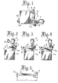
- Fig. 1 there is shown a known tunneling scanning microscope which incorporates apparatus comprising a base 1 a in which are slidably mounted two rods 3 which are supported in respective journal bearings 2. Pivotally secured to the rods 3 at a pivot axis 6 a is an arm 6 which is provided with means for carrying a sample 8.
- the rods 3 may be moved by a screw jack 10 in the direction of the arrow so as to allow the arm 6, under the control of a stop 5, to pivot from a position shown in Fig. 2, in which the sample 8 is spaced from a foot or stopper 7 carried by the base 1 a , to a position shown in Fig. 3 in which there is contact between the sample 8 and the stopper 7 and between the arm 6 and a stopper 4 carried by the rods 3.
- the sample 8 is disposed relatively close to a scanning probe 9.
- Movement of the sample 8 from the Fig. 3 to the Fig. 4 position effects fine adjustment of the distance between the sample 8 and the scanning probe 9.
- the extent to which the sample 8 moves with respect to the scanning probe 9 as a result of a predetermined amount of movement of the rods 3 is substantially reduced once contact occurs between the sample 8 and the stopper 7. Thereafter the movement of the sample 8 is reduced to ⁇ l/l of its previous value, where l is the distance of the stopper 7 from the pivot axis 6 a , and ⁇ l is the distance between the stopper 7 and the scanning probe 9 (see Fig. 5).
- the only way in which the ratio ⁇ l/l can be reduced so as to permit a finer degree of adjustment of the position of the sample 8 with respect to the scanning probe 9 is to increase the length of the arm 6, which is not practicable if the apparatus is required to be small.
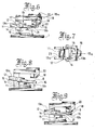
- Fig. 6 and Fig. 7 show a base 1 and a main support 11 firmly secured thereto, and a flexible arm assembly 13 pivotally held by a pin joint means or dowel pin 12 which is mounted in a plurality of bearings 23 arranged in the main support 11.
- the arm assembly consists of two arm members, namely a first arm member 13 a and a second arm member 13 b , which are connected together at a pivot means 14, and a plurality of leaf springs 15 which impose a load on the two arm members 13 a , 13 b and urge them towards a position, as shown in Fig. 6, in which they are aligned with each other.
- the second arm member 13 b is free to pivot about the axis of the pivot means 14.
- each of the arms 13 a , 13 b is U-shaped in plan, the arm 13 a having a projection 13 c which is engaged by a jack means 21.
- the limbs of the arm 13 b carry a pair of pivots which constitute the pivot means 14 and which pivotally engage the limbs of the arm 13 a .
- a sample holder 16 is mounted adjacent to the free end of the second arm 13 b , and a sample 8 is shown as being fixed to the sample holder 16.
- a rigid stationary arm 17 is firmly fixed at the top of the main support 11, the flexible arm assembly 13 being disposed opposite to the rigid arm 17.
- a "foot” or stopper 18 is attached to a foot holder 18 a which is mounted on the rigid arm 17, the foot 18 being disposed opposite to the flexible arm assembly 13. Fine adjustment of the foot 18, both horizontally over the arm assembly 13 and also vertically, is possible by a foot location adjusting means 22.
- a fine pointed scanning tip 20 is mounted on a scanning tip 3-D actuator means 19 which is firmly attached to the rigid arm 17 at a place adjacent to the foot 18.
- the jack means 21 is rigidly mounted on the base 1 for applying motion to a point on the projection 13 c of the arm member 13 a , which we refer to here as the first point of load. Movements of the components in this embodiment are illustrated in Fig. 8, Fig. 9, Fig. 10 and Fig. 11.
- the motion of the jack means 21 is reduced by a first lever action to the ratio of " b “ to " a ", “ b “ being the distance between the axis of the pin joint 12 and the axis of the pivot means 14 which we refer to here as the first working point; and " a “ being the distance between the axis of the pin joint means 12 and a point on the projection 13 c of the arm 13 a which we refer to here as the first point of load on the first arm member 13 a at which the jack means 21 applies motion thereto.
- the distances a , b are shown in Fig. 11 which is, however, a purely diagrammatic drawing.
- this reduced motion is further reduced by a second lever action of the second arm member 13 b which has a point of load at the place in common with the first working point which we refer to here as the second point of load, and which pivots about the foot 18.
- the foot-to-scanning tip separation of ⁇ l (Fig. 11) and the distance c between the axis of the pivot means 14 and the foot 18, give a translational reduction of ⁇ l/c. Therefore, the double-lever-action gives a total translational reduction of ( b / a ) X ( ⁇ l/ c ).
- the measurements of a , b , c , and ⁇ l are set at 25mm, 10mm, 40mm, and 1mm respectively. This set of measurements thus gives a translational reduction of 100 to 1.
- FIG. 12 An alternative design is shown in Fig. 12 as having inverted positions between the sample 8 and the scanning tip 20.
- the design of Fig. 12 provides the same translational reduction and same precise and fine control over the scanning tip-to-sample distance as in the embodiment of Figs. 6 to 11.
- Figs. 13 to 17 show another embodiment of the present invention having a piezo-electric drive means 24 placed on top of the jack means 21 for providing more precise vibration-free control over the fine approach between the sample 8 and the scanning tip 20.
- the piezo-electric drive means 24 placed on top of the jack means 21 is actuated so as to produce extremely fine motion at the first point of load, thus providing precise and minute control over the scanning tip to sample distance.
- Fig. 13 and Fig. 14 show a base 1 and a main support 11 firmly secured thereto and an arm assembly 13 pivotally held by a pin joint means 12 which is mounted in a plurality of bearings 23 arranged in the main support 11.
- the arm assembly 13 consists of two arm members, i.e. a first arm member 13 a and a second arm member 13 b , a pivot means 14 connecting the first arm member 13 a and the second arm member 13 b together, and a plurality of leaf springs 15 such that the two arm members 13 a ,13 b are spring-loaded thereby.
- the first and second arm members, 13 a and 13 b are free to pivot about the pivot means 14.
- a sample holder 16 is mounted adjacent to the free end of the second arm 13 b , and a sample 8 is shown as being fixed to the sample holder 16.
- the piezo-electric drive means 24 which is connected to a control power source 25 and a control member 25 a , is placed on top of the jack means 21.
- a rigid arm 17 is firmly fixed at the top of the main support 11, and a foot 18 is attached to a foot holder 18 a mounted on the rigid arm 17. The foot 18 can be finely adjusted horizontally along the arm assembly and vertically.
- a fine pointed scanning tip 20 is mounted on a scanning tip fine drive means 19 which is firmly attached to the rigid arm 17 at a place adjacent to the foot 18.
- the jack means 21 is firmly mounted on the base 1 for providing motion to a point of load in the arm assembly 13 which we refer to here as the first point of load.
- the motion of the jack means 21 at the first point of load on the arm member 13 a is reduced, so far as its application to the arm member 13 b is concerned, through a double-lever-action to fine displacement between the scanning tip 20 and the sample 8 in the manner previously described with reference to the accompanying Figs. 6 to 11.
- Motion at the first point of load during rather large pivoting of the arm 13, i.e. coarse approach is provided by the jack means 21.
- motion at the first point of load is produced by energizing the piezo-electric drive means 24 which is mounted on the arm member 13 b and contacts the jack means 21.
- a multilayer piezo-actuator (a multilayer PZT actuator) of 10mm in diameter and 5mm thick may be used as the piezo-electric drive means.
- the amount of displacement of the multilayer piezo-actuator can be controlled precisely and finely in proportion to the magnitude of the voltage applied thereto. Displacement of the multilayer piezo-actuator is reduced to the ratio of 100 to 1 in the case of this embodiment.
- Fig. 18 An alternative design is shown in Fig. 18 which is generally similar to that of Figs. 13 to 17.
- the design of Fig. 18 has inverted positions between the sample 8 and the scanning tip 20 but nevertheless produces the same translational reduction and fine and precise control over the sample to scanning tip distance.
- Figs. 19 to 23 there is shown another embodiment of the present invention having a multilayer piezo-electric actuator 26 placed between a scanning tip 3-D actuator means 19 and a rigid arm 17 for providing precise minute displacement during the fine approach between the sample 8 and the fine pointed scanning tip 20.
- Fig. 19 and Fig. 20 show a base 1 and a main support 11 firmly fixed thereto and an arm assembly 13 pivotally held by a pin joint means 12 which is mounted in a plurality of bearings 23 arranged in the main support 11.
- the arm assembly 13 consists of two arm members, 13 a and 13 b , which are spring-loaded by a plurality of leaf springs 15 at the joint and pivot about a pivot means 14 in one direction.
- a sample holder 16 is mounted adjacent to the free end of the arm member 13 b , and a sample 8 is shown as being fixed to the sample holder 16.
- a multilayer piezo-electric actuator 26 placed between the rigid arm 17 and the scanning tip 3-D actuator means 19.
- the actuator 26 is disposed in a circuit comprising a power source 27 and control 27 a .
- the rigid arm 17 is firmly fixed on top of the main support 11, and a foot 18 is attached to a foot holder 18 a mounted on the rigid arm 17.
- the foot 18 can be finely adjusted horizontally over the arm assembly and vertically.
- the fine pointed scanning tip 20 is secured to the scanning tip 3-D actuator means 19 which is itself firmly attached to the rigid arm 17 in close proximity to the foot 18.
- a jack means 21 is firmly fixed on the base 1 for applying motion to the arm assembly 13.
- the motions of the arm assembly during the coarse pivotal movement, and the approach of the sample to the scanning tip are effected by the jack means 21.
- motion to be applied to the first point of load is produced by energizing the multilayer piezo-electric actuator 26 which is placed between the rigid arm 17 and the scanning tip 3-D actuator means 19.
- a multilayer piezo actuator of 10 mm in diameter and 5mm thick may be used.
- Fig. 24 An alternative design is shown in Fig. 24 which is generally similar to that of Figs. 19-23.
- the design of Fig. 24 has inverted positions between the sample 8 and the scanning tip 20 but nevertheless produces the same translational reduction and same fine and precise control over the sample to scanning tip distance.
Landscapes
- Chemical & Material Sciences (AREA)
- Analytical Chemistry (AREA)
- Nuclear Medicine, Radiotherapy & Molecular Imaging (AREA)
- Health & Medical Sciences (AREA)
- General Health & Medical Sciences (AREA)
- General Physics & Mathematics (AREA)
- Physics & Mathematics (AREA)
- Radiology & Medical Imaging (AREA)
- Engineering & Computer Science (AREA)
- Nanotechnology (AREA)
- Crystallography & Structural Chemistry (AREA)
- Length Measuring Devices With Unspecified Measuring Means (AREA)
- Mechanical Control Devices (AREA)
Applications Claiming Priority (6)
| Application Number | Priority Date | Filing Date | Title |
|---|---|---|---|
| JP16414686A JPH0612379B2 (ja) | 1986-07-11 | 1986-07-11 | 微小位置決め装置 |
| JP164146/86 | 1986-07-11 | ||
| JP16414586A JPH0612378B2 (ja) | 1986-07-11 | 1986-07-11 | 微小位置決め装置 |
| JP164145/86 | 1986-07-11 | ||
| JP289157/86 | 1986-12-04 | ||
| JP28915786A JPH0652487B2 (ja) | 1986-12-04 | 1986-12-04 | 微小位置決め機構 |
Publications (2)
| Publication Number | Publication Date |
|---|---|
| EP0252745A2 true EP0252745A2 (de) | 1988-01-13 |
| EP0252745A3 EP0252745A3 (de) | 1990-01-24 |
Family
ID=27322279
Family Applications (1)
| Application Number | Title | Priority Date | Filing Date |
|---|---|---|---|
| EP87306090A Withdrawn EP0252745A3 (de) | 1986-07-11 | 1987-07-09 | Gerät zum Steuern relativer Verschiebungen |
Country Status (2)
| Country | Link |
|---|---|
| US (1) | US4866271A (de) |
| EP (1) | EP0252745A3 (de) |
Cited By (3)
| Publication number | Priority date | Publication date | Assignee | Title |
|---|---|---|---|---|
| US4853810A (en) * | 1985-11-19 | 1989-08-01 | International Business Machines Corporation | Method and apparatus for controlling the flying height of the head in a magnetic storage unit |
| US4925139A (en) * | 1989-04-28 | 1990-05-15 | International Business Machines Corporation | Mechanical stage support for a scanning tunneling microscope |
| EP0349911A3 (de) * | 1988-07-03 | 1991-07-17 | Forschungszentrum Jülich Gmbh | Mikromanipulator |
Families Citing this family (18)
| Publication number | Priority date | Publication date | Assignee | Title |
|---|---|---|---|---|
| EP0304893B1 (de) * | 1987-08-25 | 1995-07-19 | Canon Kabushiki Kaisha | Codiereinrichtung |
| JP2909828B2 (ja) * | 1989-07-05 | 1999-06-23 | セイコーインスツルメンツ株式会社 | 複合走査型トンネル顕微鏡 |
| US5055680A (en) * | 1990-04-03 | 1991-10-08 | Lk Technologies, Inc. | Scanning tunneling microscope |
| US5394741A (en) * | 1990-07-11 | 1995-03-07 | Olympus Optical Co., Ltd. | Atomic probe microscope |
| US5245863A (en) * | 1990-07-11 | 1993-09-21 | Olympus Optical Co., Ltd. | Atomic probe microscope |
| US5155361A (en) * | 1991-07-26 | 1992-10-13 | The Arizona Board Of Regents, A Body Corporate Acting For And On Behalf Of Arizona State University | Potentiostatic preparation of molecular adsorbates for scanning probe microscopy |
| US5440920A (en) * | 1994-02-03 | 1995-08-15 | Molecular Imaging Systems | Scanning force microscope with beam tracking lens |
| US5515719A (en) * | 1994-05-19 | 1996-05-14 | Molecular Imaging Corporation | Controlled force microscope for operation in liquids |
| US5753814A (en) * | 1994-05-19 | 1998-05-19 | Molecular Imaging Corporation | Magnetically-oscillated probe microscope for operation in liquids |
| US5513518A (en) * | 1994-05-19 | 1996-05-07 | Molecular Imaging Corporation | Magnetic modulation of force sensor for AC detection in an atomic force microscope |
| US5866805A (en) * | 1994-05-19 | 1999-02-02 | Molecular Imaging Corporation Arizona Board Of Regents | Cantilevers for a magnetically driven atomic force microscope |
| US5675154A (en) * | 1995-02-10 | 1997-10-07 | Molecular Imaging Corporation | Scanning probe microscope |
| US5621210A (en) * | 1995-02-10 | 1997-04-15 | Molecular Imaging Corporation | Microscope for force and tunneling microscopy in liquids |
| US5750989A (en) * | 1995-02-10 | 1998-05-12 | Molecular Imaging Corporation | Scanning probe microscope for use in fluids |
| US5654546A (en) * | 1995-11-07 | 1997-08-05 | Molecular Imaging Corporation | Variable temperature scanning probe microscope based on a peltier device |
| US5821545A (en) * | 1995-11-07 | 1998-10-13 | Molecular Imaging Corporation | Heated stage for a scanning probe microscope |
| US6744268B2 (en) * | 1998-08-27 | 2004-06-01 | The Micromanipulator Company, Inc. | High resolution analytical probe station |
| US6198299B1 (en) * | 1998-08-27 | 2001-03-06 | The Micromanipulator Company, Inc. | High Resolution analytical probe station |
Family Cites Families (5)
| Publication number | Priority date | Publication date | Assignee | Title |
|---|---|---|---|---|
| CH643397A5 (de) * | 1979-09-20 | 1984-05-30 | Ibm | Raster-tunnelmikroskop. |
| DE3570012D1 (en) * | 1985-01-29 | 1989-06-08 | Ibm | Field-emission scanning auger electron microscope |
| DE3572030D1 (en) * | 1985-03-07 | 1989-09-07 | Ibm | Scanning tunneling microscope |
| US4665313A (en) * | 1985-06-28 | 1987-05-12 | International Business Machines Corporation | Apparatus and method for displaying hole-electron pair distributions induced by electron bombardment |
| US4724318A (en) * | 1985-11-26 | 1988-02-09 | International Business Machines Corporation | Atomic force microscope and method for imaging surfaces with atomic resolution |
-
1987
- 1987-07-09 EP EP87306090A patent/EP0252745A3/de not_active Withdrawn
- 1987-07-10 US US07/071,994 patent/US4866271A/en not_active Expired - Lifetime
Non-Patent Citations (2)
| Title |
|---|
| IBM TECHNICAL DISCLOSURE BULLETIN, vol. 28, no. 10, March 1986, pages 4356-4357, New York, US: "Simplified scanning tunnelling microscope for surface topography measurements" * |
| JOURNAL OF VACUUM SCIENCE & TECHNOLOGY A, vol. 4, no. 3, May-June 1986, part II, second series, pages 1320-1323, American Vacuum Society, New York, NY, US; J.E. DEMUTH et al.: "A simplified scanning tunneling microscope for surface science studies" * |
Cited By (3)
| Publication number | Priority date | Publication date | Assignee | Title |
|---|---|---|---|---|
| US4853810A (en) * | 1985-11-19 | 1989-08-01 | International Business Machines Corporation | Method and apparatus for controlling the flying height of the head in a magnetic storage unit |
| EP0349911A3 (de) * | 1988-07-03 | 1991-07-17 | Forschungszentrum Jülich Gmbh | Mikromanipulator |
| US4925139A (en) * | 1989-04-28 | 1990-05-15 | International Business Machines Corporation | Mechanical stage support for a scanning tunneling microscope |
Also Published As
| Publication number | Publication date |
|---|---|
| EP0252745A3 (de) | 1990-01-24 |
| US4866271A (en) | 1989-09-12 |
Similar Documents
| Publication | Publication Date | Title |
|---|---|---|
| EP0252745A2 (de) | Gerät zum Steuern relativer Verschiebungen | |
| EP0864181B1 (de) | Flacher abtasttisch für rastersonden-mikroskopie | |
| US6809306B2 (en) | Scanning unit and scanning microscope having the same | |
| US6612160B2 (en) | Apparatus and method for isolating and measuring movement in metrology apparatus | |
| EP0475564A1 (de) | Fein-Abtastmechanismus für Atomkraft-Mikroskop | |
| US5286977A (en) | Positioning device | |
| JP2005517911A (ja) | 走査型プローブ顕微鏡 | |
| US4762996A (en) | Coarse approach positioning device | |
| US5438206A (en) | Positioning device | |
| US6021665A (en) | Cantilever tracking type scanning probe microscope | |
| Bergander et al. | Micropositioners for microscopy applications based on the stick-slip effect | |
| EP0394914B1 (de) | Mechanische Objektplatte, insbesondere für ein Tunneleffektmikroskop | |
| EP0843151B1 (de) | Abtastgerät für Probenmikroskop | |
| JPS6052230A (ja) | 微動ステ−ジ機構 | |
| EP0252174B1 (de) | Grobstellanordnung | |
| Zhang et al. | A linear piezomotor of high stiffness and nanometer resolution | |
| JP2001022445A (ja) | 変位拡大機構 | |
| JP3369892B2 (ja) | 微小位置決め装置用の位置決め器 | |
| CN110082232A (zh) | 一种加持装置及显微镜 | |
| JP2008051690A (ja) | 光学式変位検出機構及びそれを用いた表面情報計測装置 | |
| JP2001133382A (ja) | 走査型プローブ顕微鏡 | |
| JPH05256642A (ja) | 原子間力顕微鏡 | |
| JP4362326B2 (ja) | 超精密移動台装置 | |
| JP2000099154A (ja) | 変位拡大機構 | |
| JPH09113520A (ja) | 可動部の支持装置及びその支持方法、並びに原子間力顕微と走査型トンネル顕微鏡との動作を兼ねた複合装置 |
Legal Events
| Date | Code | Title | Description |
|---|---|---|---|
| PUAI | Public reference made under article 153(3) epc to a published international application that has entered the european phase |
Free format text: ORIGINAL CODE: 0009012 |
|
| AK | Designated contracting states |
Kind code of ref document: A2 Designated state(s): DE FR GB |
|
| PUAL | Search report despatched |
Free format text: ORIGINAL CODE: 0009013 |
|
| AK | Designated contracting states |
Kind code of ref document: A3 Designated state(s): DE FR GB |
|
| 17P | Request for examination filed |
Effective date: 19900604 |
|
| 17Q | First examination report despatched |
Effective date: 19920626 |
|
| STAA | Information on the status of an ep patent application or granted ep patent |
Free format text: STATUS: THE APPLICATION IS DEEMED TO BE WITHDRAWN |
|
| 18D | Application deemed to be withdrawn |
Effective date: 19940201 |
|
| RIN1 | Information on inventor provided before grant (corrected) |
Inventor name: SAKAI, FUMIKI Inventor name: MURAKAMI, HIROSHIMINISTRY OF INT. TRADE AND IND. Inventor name: BANDO, HIROSHIMINISTRY OF INT. TRADE AND IND. Inventor name: MIZUTANI, WATARUMINISTRY OF INT. TRADE AND IND. Inventor name: WAKIYAMA, SHIGERU Inventor name: WAKATSUKI, TAKASHI Inventor name: ONO, MASATOSHIMINISTRY OF INT. TRADE AND IND. |