EP0252807A1 - Einrichtung zur Detektion und räumlichen Ortung durch interferometrische Messung von Blitzentladungen in Echtzeit und auf weite Entfernung - Google Patents
Einrichtung zur Detektion und räumlichen Ortung durch interferometrische Messung von Blitzentladungen in Echtzeit und auf weite Entfernung Download PDFInfo
- Publication number
- EP0252807A1 EP0252807A1 EP87401519A EP87401519A EP0252807A1 EP 0252807 A1 EP0252807 A1 EP 0252807A1 EP 87401519 A EP87401519 A EP 87401519A EP 87401519 A EP87401519 A EP 87401519A EP 0252807 A1 EP0252807 A1 EP 0252807A1
- Authority
- EP
- European Patent Office
- Prior art keywords
- stations
- antennas
- information
- time
- location
- Prior art date
- Legal status (The legal status is an assumption and is not a legal conclusion. Google has not performed a legal analysis and makes no representation as to the accuracy of the status listed.)
- Granted
Links
Images


Classifications
-
- G—PHYSICS
- G01—MEASURING; TESTING
- G01S—RADIO DIRECTION-FINDING; RADIO NAVIGATION; DETERMINING DISTANCE OR VELOCITY BY USE OF RADIO WAVES; LOCATING OR PRESENCE-DETECTING BY USE OF THE REFLECTION OR RERADIATION OF RADIO WAVES; ANALOGOUS ARRANGEMENTS USING OTHER WAVES
- G01S5/00—Position-fixing by co-ordinating two or more direction or position line determinations; Position-fixing by co-ordinating two or more distance determinations
- G01S5/0009—Transmission of position information to remote stations
-
- G—PHYSICS
- G01—MEASURING; TESTING
- G01S—RADIO DIRECTION-FINDING; RADIO NAVIGATION; DETERMINING DISTANCE OR VELOCITY BY USE OF RADIO WAVES; LOCATING OR PRESENCE-DETECTING BY USE OF THE REFLECTION OR RERADIATION OF RADIO WAVES; ANALOGOUS ARRANGEMENTS USING OTHER WAVES
- G01S3/00—Direction-finders for determining the direction from which infrasonic, sonic, ultrasonic or electromagnetic waves, or particle emission, not having a directional significance, are being received
- G01S3/02—Direction-finders for determining the direction from which infrasonic, sonic, ultrasonic or electromagnetic waves, or particle emission, not having a directional significance, are being received using radio waves
- G01S3/14—Systems for determining direction or deviation from predetermined direction
- G01S3/46—Systems for determining direction or deviation from predetermined direction using antennas spaced apart and measuring phase or time difference between signals therefrom, i.e. path-difference systems
- G01S3/48—Systems for determining direction or deviation from predetermined direction using antennas spaced apart and measuring phase or time difference between signals therefrom, i.e. path-difference systems the waves arriving at the antennas being continuous or intermittent and the phase difference of signals derived therefrom being measured
-
- G—PHYSICS
- G01—MEASURING; TESTING
- G01S—RADIO DIRECTION-FINDING; RADIO NAVIGATION; DETERMINING DISTANCE OR VELOCITY BY USE OF RADIO WAVES; LOCATING OR PRESENCE-DETECTING BY USE OF THE REFLECTION OR RERADIATION OF RADIO WAVES; ANALOGOUS ARRANGEMENTS USING OTHER WAVES
- G01S5/00—Position-fixing by co-ordinating two or more direction or position line determinations; Position-fixing by co-ordinating two or more distance determinations
- G01S5/02—Position-fixing by co-ordinating two or more direction or position line determinations; Position-fixing by co-ordinating two or more distance determinations using radio waves
- G01S5/04—Position of source determined by a plurality of spaced direction-finders
-
- G—PHYSICS
- G01—MEASURING; TESTING
- G01W—METEOROLOGY
- G01W1/00—Meteorology
- G01W1/16—Measuring atmospheric potential differences, e.g. due to electrical charges in clouds
-
- Y—GENERAL TAGGING OF NEW TECHNOLOGICAL DEVELOPMENTS; GENERAL TAGGING OF CROSS-SECTIONAL TECHNOLOGIES SPANNING OVER SEVERAL SECTIONS OF THE IPC; TECHNICAL SUBJECTS COVERED BY FORMER USPC CROSS-REFERENCE ART COLLECTIONS [XRACs] AND DIGESTS
- Y02—TECHNOLOGIES OR APPLICATIONS FOR MITIGATION OR ADAPTATION AGAINST CLIMATE CHANGE
- Y02A—TECHNOLOGIES FOR ADAPTATION TO CLIMATE CHANGE
- Y02A90/00—Technologies having an indirect contribution to adaptation to climate change
- Y02A90/10—Information and communication technologies [ICT] supporting adaptation to climate change, e.g. for weather forecasting or climate simulation
Definitions
- the present invention relates to the field of detection and spatial localization by interferometric measurement, in real time and over a long distance, of lightning discharges, and more particularly it relates to an installation, for such detection and localization, which comprises at least two angular landfill location stations, located at a medium distance from each other, each station comprising: / at least two fixed antennas for receiving at least one electromagnetic radiation of predetermined wavelength generated by lightning discharges, and / means for interferometric processing of the signals delivered by the antennas, arranged to provide information representative of the site and / or of the azimuth of the source of electromagnetic radiation constituted by the lightning discharge.
- a measurement of this type makes it possible to locate the source in a cone centered on the axis passing through the two antennas and of angle at the apex ⁇ .
- a second interferometric base i.e. a third antenna (since the same antenna is used as a reference for phase), allows you to find the original direction of the source, in azimuth and in elevation. From the azimuth and site information obtained at two location stations, it is then possible, by deferred time calculation, to determine, by triangulation, the spatial position of the source.
- a known installation for spatial location of lightning discharges comprises two stations for angular location of the discharges, each of the stations comprising two sets of three antennas.
- the first set consists of three antennas which are mutually separated by a relatively large distance (for example 10 m for an operating frequency of 300 MHz); it allows precise localization of the source but with a large number of ambiguities (since the phase measurement is made to within 2 ⁇ ).
- the second set consists of three mutually separate antennas of a relatively short distance (for example 0.5 m) and makes it possible to resolve the ambiguities of localization of the first system.
- interferometric localization is freed from dependence on the shapes. of lightning signal waves, by measurements relating only to the phase of the signal. This allows measurements on large dynamics (typically 80 dB), which adapts perfectly to the large variations in signal level due to the emission dynamics of the sources, as well as to the large extent of the monitoring domain.
- the invention therefore essentially aims to design an installation for the detection and spatial localization, in real time and over a long distance, of lightning discharges making it possible to ensure an operational monitoring function with a technical structure and minimum maintenance.
- each station further comprises: / threshold validation means sensitive to at least one quantity of electromagnetic radiation received (in particular its emission density and / or its amplitude), arranged to deliver a control signal if said quantity is greater than a preset threshold, / information sorting means placed under the dependence of the above threshold validation means, for selecting the angular information provided by the interferometric processing means, only when the said quantity is greater than its preset value, / means for training and processing digital data arranged so that each of these digital data consists of information representative of the site and / or the azimuth, selected by the sorting means and by information representing the date of the lightning discharge, / temporary storage means of the digital data thus constituted, these storage means retaining said digital data for a time depending on the possible transmission rate, / and means for transmitting, in a transmission line, digital data; said installation being further characterized in that it comprises: - transmission lines respectively connecting the above-mentioned location stations to a digital data acquisition
- the installation comprises at least three non-mutually aligned location stations, which it also comprises means for determining the two stations capable of providing, on a given date, the spatial position with the best accuracy, and that the sorting means of the digital data acquisition center are arranged to select pairs of information of the same date collected by the two stations providing the best accuracy on this date.
- the location stations respectively have time bases synchronized from a common synchronization source and means for taking into account the respective delays undergone by the synchronization signals in the respective transmission lines.
- the common synchronization source includes means for generating synchronization signals of substantially square shape, having a frequency of approximately 1 Hz, of duty cycle substantially equal to 1 and frequency modulated, and storage means which contain corresponding values at an elementary period of the modulation frequency and which are sent by a clock signal constituted by the above signal synchronization
- connection means are provided between the aforementioned common synchronization source and the respective time bases of the location stations for transmitting to said time bases the output signals of the storage means
- - and each time base of a location station includes: / means for filtering and shaping the received signal, / means for determining the instants of frequency change of said received signal, / selection means for selecting from this signal a stable synchronization signal, / delay means, coupled with the aforementioned means for taking into account the delay introduced by the duration of the transmission in the aforementioned link means with respect to the duration of transmission in the link means with the other location stations, / and means for outputting a time base synchronized and compensated signal.
- the threshold validation means are sensitive in particular to the emission density and include: counting means arranged to carry out a counting for a predetermined duration T from the time they are started, means for detecting the presence, on the receiving antennas, of electromagnetic radiation to be detected, trigger means, controlled by the above detection means, for triggering the start of the above counting means, - comparator means for comparing the output signal of the counting means at the end of a time T with a predetermined threshold, - And means for storing the result of this comparison having a first voltage level if the count is less than the predetermined threshold or a second voltage level if the count is greater than said threshold.
- each location station In the case where it is desired to perform an omnidirectional detection, it is possible to have each location station have three simple omnidirectional antennas in azimuth, these antennas being arranged in a triangle and being chosen from the monopole types ⁇ / 4 on plane, monopole 5 ⁇ / 8 on plane or dipole ⁇ / 2 ( ⁇ being the wavelength of the electromagnetic radiation to be detected). In this case, to avoid coupling problems between antennas, it is desirable that the antennas have a relatively low directivity in elevation, in particular less than or equal to 3 dB.
- each location station comprises directional antennas in azimuth, in particular arranged for detection in a limited angular range or else arranged for a isotropic detection in azimuth by combination of several antennas pointed in complementary directions.
- the antennas of each station are mutually spaced about half a wavelength from the radiation to be detected.
- the installation according to the invention may include means for determining the differences in arrival times, at the data acquisition center, of the digital data coming from different location stations. and that the computing means are arranged to use this time difference information of arrival together with the other sorted and associated site and / or azimuth information, so that it is possible to locate the source of electromagnetic radiation constituted by the lightning discharge from a system ambiguous antennas, but providing better angular resolution.
- the installation also includes calibration means, including an emitter of electromagnetic radiation of the frequency to be detected and means for detecting and calculating the proper phase shift of the installation, which makes it possible to correct the measurements.
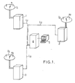
- FIG. 1 The installation for spatial detection and localization by interferometric means, in real time and at a long distance from lightning discharges is shown, as a whole and very schematically, in FIG. 1.
- the installation includes a certain number of measurement stations, represented here three in number respectively referenced 1, 2 and 3, respectively equipped with antennas I1, I2, I3, which are connected by transmission lines L1, L2 and L3 to a central data acquisition unit 4, itself connected to a real-time data processing unit 5.
- a certain number of measurement stations represented here three in number respectively referenced 1, 2 and 3, respectively equipped with antennas I1, I2, I3, which are connected by transmission lines L1, L2 and L3 to a central data acquisition unit 4, itself connected to a real-time data processing unit 5.
- the location of the thunderstorm activity being done by triangulation, the geometry of implantation of the measurement stations is to be optimized according to the extent of the field of observation, as well as the availability of the implantation sites.
- VHF-UHF radiation sources associated with lightning the level of the VHF-UHF radiation sources associated with lightning, the altitude of these sources (typically 0 to 10 km) as well as the altitude of each receiving station. For typical situations, this detection distance can be estimated from 150 km to 200 km.
- the distance between stations will be comparable to the dimensions of the observation area (typically 100 to 200 km).
- Two stations are sufficient when the observation range is outside the axis of the stations; three are preferable since the area covers areas between the stations.
- the receiver operating frequency can be chosen in the VHF-UHF range, for example in the vicinity of 140 MHz (hence a half wavelength on the order of 1 meter).
- This frequency range provides access to sources of radiation present in all phases of lightning, and therefore allows the localization of all atmospheric discharge phenomena such as the precursor mechanisms of lightning strikes on the ground, the return wave of the cloud-ground arc, or the intra-cloud mechanisms.
- the three antennas 61 to 63 respectively provide three pairs of magnitudes, respectively the amplitude A1, A2 and A3 and the phase ⁇ 1, ⁇ 2 and ⁇ 3, of the detected electromagnetic radiation.
- the output signals from the three antennas are sent to an interferometric processing unit 15, comprising filtering, amplification and frequency change means (at 16), then VHF receiver means (at 17), and finally means analog phase processing (in 18) providing the cosine (cos ⁇ 12) and the sine (sin ⁇ 12) of the phase shift angle between the signals received by the antennas 61 and 62 and the cosine (cos ⁇ 13) and the sine ( sin ⁇ 13) of the phase shift angle between the signals received by the antennas 61 and 63.
- an interferometric processing unit 15 comprising filtering, amplification and frequency change means (at 16), then VHF receiver means (at 17), and finally means analog phase processing (in 18) providing the cosine (cos ⁇ 12) and the sine (sin ⁇ 12) of the phase shift angle between the signals received by the antennas 61 and 62 and the cosine (cos ⁇ 13) and the sine ( sin ⁇ 13) of the phase shift angle between the signals received by the antennas
- Such an interferometric processing unit 15 is already known.
- the three antennas 61 to 63, of the monopole type ⁇ / 4 on plan, are respectively connected to three filters 19 paired in phase typically having a bandwidth of 10 MHz centered on a frequency of 140 MHz.
- These filters 19 are respectively connected to three frequency changing devices 20 also connected to a frequency generator 21 of 170 MHz typically.
- the frequency change devices 20 are respectively connected to three intermediate frequency filters 22 paired in phase and typically having a bandwidth of 1 MHz centered on the frequency of 30 MHz.
- These filters are connected to three limiting amplifiers 23 typically having a limiting dynamic range of 80 dB, which are themselves connected to three distributors 24.
- the latter are connected to four mixers 25 either directly for the two mixers of the cosine channels, or by ⁇ / 2 26 phase shifter (for one of their inputs) for the two sinus mixer.
- the mixers are finally connected respectively to four low frequency filters 27, having a typical bandwidth of around 0-5 kHz, themselves connected respectively to four output amplifiers 28.
- the signals supplied by the interferometric processing unit 15 are then processed digitally, in a digital processing unit 29.
- the digital processing unit 29 firstly comprises a digitization and processing circuit 30 which respectively ensures the analog / digital conversion of the information cos ⁇ 12, sin ⁇ 12, cos ⁇ 13 and sin ⁇ 13 and the calculation of the angular direction in elevation and / or azimuth of the radiation source relative to the station.
- the amplitude selection makes it possible to give an acquisition threshold and therefore to define a measurement quality (by indirect selection of the minimum signal-to-noise ratio). It can also be seen as a means of limiting the scope.
- emission density relates directly to the emission mechanisms associated with atmospheric discharges.
- This emission density can be defined in the time resolution window of the measurement as the percentage of time during which the radiation is present (for example number of microseconds of emission in the analysis window of 100 ⁇ s).
- This selection mode associated with a finely resolved measurement in time provides access to the spatial extension of the discharges.
- Lightning discharges indeed present, during the process, intense emissions lasting several hundreds of microseconds and extending over distances that can exceed ten kilometers.
- the possibility of sampling these discharges at several points (one for each hundred ⁇ s), associated with the knowledge of the emission density allows a reconstruction of the path of the discharge and therefore leads to the knowledge of the extension of the region lightning strike.
- the large temporal resolution of the measurement also makes it possible to limit the probability of occurrence, spatially distinct discharges in the same time window.
- the selection criterion on the emission density can allow the elimination of sporadic spurious signals.
- FIG. 7 represents the electronic diagram of an exemplary embodiment of the validation circuit.
- the signal emission density detection circuit 32 includes an AND gate 35, an input of which is connected to a clock H ⁇ (not shown) delivering a signal of period T / N, T being the period of recurrence of the measurements and 1 / N being the desired resolution for these measurements; the other input of the AND gate 35 receives a logic signal VALEM which is worth 1 when there is emission of radiation and 0 otherwise.
- the output of the AND gate 35 is connected to an input of a counter 36, the reset input of which is connected to a clock H providing a signal of period T.
- the output of the counter 36 is connected to the input of the validation circuit 33, in other words to the input of a comparator 37, the other input of which is connected to the threshold programming circuit 34.
- the comparator output 37 is connected at the input of a flip-flop 38 of type D whose clock input receives the clock signal H of period T.
- this emission density value can be kept as a characterization element as indicated below.
- the angular direction in azimuth and / or in elevation of the radiation source relative to the station is then calculated, taking into account any necessary corrections (calibrations, couplings between antennas, effects of environment, etc.).
- the digital data thus formed are then transmitted (transmission circuit 41) in any suitable manner, for example via a modulator 42 of appropriate speed and a normal or special telephone line 43, to the central data acquisition unit 4.
- the storage of the data in 39 makes it possible to spread out over time the supply of the data to be transmitted to the transmission means: the latter therefore do not have to have too large a transmission capacity and their cost is reduced by as much.
- the central data acquisition unit 4 receives simultaneously, via example of the respective telephone lines 431, 432 and 433 and of the respective demodulators 441, 442 and 443, the digital data coming from the measurement stations 1, 2 and 3, data which are assigned to acquisition circuits 451, 452 and 453 respectively.
- a sorting unit 46 performs a time sorting of the data thus received and keeps only the digital data of the same date common to at least two stations and this data is rearranged, then stored in memory at 47 before being supplied to the unit. 5 real-time data processing.
- the presence of the storage means 47 therefore makes it possible, here again, to spread the transmission of data over time to the processing unit 5 and therefore to adapt this transmission to the computing capacity of this unit 5, which can be less widely dimensioned and can therefore be less costly.
- the management of the data acquisition unit 4 is synchronized at the same rate as the processing units of the angular location stations (link 48).
- the real-time data processing unit 5, shown in FIG. 9, includes a calculation unit 49 which receives and reads (at 50) the data coming from the acquisition unit 4, takes into account the various calibration data which are communicated to it (at 51) and performs (at 52) the proper calculation of the location of the radiation source (lightning discharge).
- the central computer chooses the two stations, among the three, which allow the best location (the criterion retained being that the source to be located is outside the axis of the two stations selected), the information coming from the third then serving means of control.
- the results of the calculation are finally formatted (in 53) of appropriately, then directed to display means (for example real-time display on screen 54a printing real-time data in 54b, storing real-time data in 54c, etc.).
- each measurement station is equipped with a clock controlled by a quartz oscillator, intended to date the events occurring at each of the stations.
- a quartz oscillator intended to date the events occurring at each of the stations.
- Each measurement made in a station is then assigned a date which will be used for the counting to determine the sets of synchronous measurements.
- the stability of the oscillators used is not sufficient, it is necessary to synchronize them periodically (for example once per second) by resetting the associated clock counters (40 in fig. 2).
- the reset "tops" are sent simultaneously to each station from a transmission box located at the level of the central unit and a reception box provided in each station ensures the shaping and creates a delay. intended to compensate for the differential delays brought by the different line lengths between the central unit and the respective stations.
- the synchronization signals are sent on dedicated lines (2 wires) connecting each of the stations to the central unit.
- the synchronization signals transmitted are square signals of frequency 1 Hz, duty cycle 1 and frequency modulated (level 0 is modulated by a frequency f1 -for example 1000 Hz- and level 1 is modulated by a frequency f2 -par example 2000 Hz-.
- the output of the divider by two circuit 59 is connected to a divider circuit by 128, 64, itself followed by a divider circuit by 1000, 60, including the output, providing a trigger signal at the frequency of 1 Hz and duty cycle 1, is connected on the one hand to the other input of the AND gate 61 and, after inversion (inverter circuit 66), to the other input of the AND gate 60 and, on the other hand, after shaping, at the reset input of the divider circuit by 128, 63.
- the three AND gates 60, 61 and 62 constitute a tripped inverter circuit supplying the divider circuit by 128, 63, a signal whose frequency is alternately from 256 kHz and 128 kHz for 500 ms.
- the divider by 128, 63 is wired as a 7-bit binary counter and, at the output, an address bus is connected to the address input of an EPROM memory 67 with 128 elements whose output is connected to a digital-analog converter 68 connected at the output to three transmission lines to the three measurement stations 1, 2 and 3 respectively.
- an adjustable synchronization circuit comprises a first monostable flip-flop 69 whose input receives the output signal, at a frequency of 1 Hz, from the divider by 1000, 65, while its trigger input is connected to the output of the divider par 2, 59, and receives the 128 kHz frequency signal.
- the output of this first monostable flip-flop is connected to the input of a second monostable flip-flop 70 whose trigger input is connected to the output of the divider by 4, 58, and receives the frequency signal 256 kHz.
- each monostable flip-flop 69, 70 is connected a circuit, respectively 71, 72, making it possible to adjust the duration of the output pulse, so that the output signal is, after amplification, a frequency synchronization signal 1 Hz sent with an adjustable delay to the central unit to synchronize the operation of this one with the three measuring stations.
- FIG. 11 shows the diagram of a box 72 for receiving the synchronization signals, which equips each of the stations 1, 2 and 3.
- the synchronization pulses received are, after amplification, sent to a bandpass filter 73, then put in 74 shape, before being applied to the input of a monostable flip-flop 75 adjustable by an adjustment circuit 75a and, simultaneously, to an input of a flip-flop 76 of type D from which the clock input receives the output signal of the monostable flip-flop 75.
- the inverting output of flip-flop 76 of type D is connected to the input of another monostable flip-flop 77 adjustable by an adjustment circuit 77a.
- flip-flop 77 The output of flip-flop 77 is applied to the clock input of another flip-flop 78 of type D whose inverting output is looped over input D and whose non-inverting output is connected to an input of a door AND 79, the other input of which receives the output signal from the monostable flip-flop 75 inverted by an AND gate 80.
- the output of the AND gate 79 is connected to the input of yet another monostable flip-flop 81, adjustable by a circuit 81a, whose output, after amplification, provides the synchronization pulses necessary for the operation of the measuring station.
- the output of the monostable flip-flop 81 is connected to the reset input of the flip-flop 78 of type D.
- a quartz clock 82 supplies a signal at the frequency of 1 MHz which, after being divided by two by a divider circuit 83 (500 kHz), is, on the one hand, applied to the clock input of the monostable flip-flop 75 and, on the other hand, after a new division by five by the divider circuit 84 (100 kHz), is applied to the respective clock inputs of the monostable flip-flops 77 and 81.
- the circuit formed by the monostable flip-flop 75 and the D-type flip-flop 76 detects the instant of frequency change in the synchronization signal received.
- the circuit formed by the monostable flip-flop 77 and the D-type flip-flop 78 makes it possible to select a subsequent pulse (for example the fifth after this frequency change), the first pulses immediately following the frequency change being affected by jittering. ) and cannot be used as a reference.
- the pulse thus selected triggers the monostable flip-flop 81 which is programmable so as to allow compensation for the differential delay introduced by the different transmission times between the transmission unit and the respective reception units of the various measurement stations.
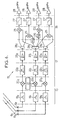
- the monostable flip-flops used are digital monostable flip-flops, the diagram of which is provided in FIG. 12.
- Each digital monostable flip-flop comprises a D type flip-flop 82 whose clock input constitutes the input of the digital monostable flip-flop, which input is also connected to an input of an AND gate 83 preventing re-triggering of the monostable.
- the inverting output of the flip-flop 82 is looped over its input and also connected to the other input of the AND gate 83, while its non-inverting output is connected to an input of a NAND gate 84 whose other input is connected to the clock input H of the digital monostable flip-flop circuit.
- the output of the door NOT AND 84 is connected to the input a counting circuit, consisting of two prepositionable decimal counters 85 and 86 (for example the one available under the reference Texas Instrument 74 192) connected in series, with a prepositioning circuit 87, allowing a display of the desired delay, acting on the weight bits 1, 2, 4, 8, 16, 32, 64 and 128.
- the output of the counter constituting the output of the digital monostable flip-flop, is connected to the reset input of flip-flop 82 of type D.
- the output of the AND gate 83 is connected, via an inverting gate 88, to the clock inputs of the counters 85 and 86.
- the counter counts between 1 and 255. If T is the period of the clock signal H, the delay which it will be possible to introduce on the signal d input can be between 1T and 255T with an error less than or equal to T.
- FIG. 11 An example of such a calibration control circuit is shown at 89 in FIG. 11. It comprises a divider by sixty 90 circuit, the input of which is connected to the output of the monostable flip-flop 81 and the output of which is connected to a programmable divider circuit, constituted for example by two up-down counters 91, 92 controlled by a prepositioning circuit 93; the output of this programmable divider circuit is connected, on the one hand, to the clock inputs of the up-down counters 91, 92 and to the reset input of the divider 90 and, on the other hand, to the clock input of a type D flip-flop 94 whose inverting output is looped over the input and whose reset input is connected to the output of the monostable flip-flop 81.
- a programmable divider circuit constituted for example by two up-down counters 91, 92 controlled by a prepositioning circuit 93; the output of this programmable divider circuit is connected, on the one hand, to the clock input
- the output of flip-flop 94 constitutes, after adaptation, the calibration command output of the station, connected to a transmitter e1, e2 and e3 placed in the antenna I1, I2 and I3 respectively of stations 1, 2 and 3 (fig. 1).
- a calibration sequence of 1 second duration is thus triggered every p minutes, the number p being manually programmable (in 93) from 0 to 255 minutes.
- this installation which has just been described with reference to FIGS. 1 to 12 makes it possible to ensure the remote detection of any notable electrical activity liable to move towards a site; this activity is linked either to convective fronts, or to isolated moving cells; this first function is essentially a medium-term monitoring and forecasting function, for example of the order of an hour or a few hours, the nominal detection distance from the active area being for example of the order of 150 km .
- the existing electrical activity is detected by the electromagnetic radiation created by lightning strikes which can be established at more or less long time intervals (from a few seconds to a few minutes).
- the associated equipment must be able to provide a location point per lightning detected (possibly several if the lightning is sufficiently energetic and of large extent); the point will be defined by its distance from the meteorological center and by its azimuth.
- the detection distance will for example be of the order of 150 km, therefore homogeneous with the radar observation distances.
- the data will be processed in two ways: - the determination of the number n of points per unit of time will make it possible to evaluate the importance of the electrical activity observed; - the evolution of the distribution of location points as a function of time will provide information on the risks that the thunderstorm system may move towards the proximity of the site in question.
- This data will allow the control center to inform operational managers of the site to be protected to: - continue or interrupt operations deemed dangerous (manipulation of propellants, pyrotechnic devices, etc.); - launch or not operations taking place over fairly long times (several hours); - assess the risks of a lightning strike during the flight of a flying device (direct or near lightning strike) even if the electrical activity above the site is not particularly marked.
Landscapes
- Engineering & Computer Science (AREA)
- Physics & Mathematics (AREA)
- General Physics & Mathematics (AREA)
- Radar, Positioning & Navigation (AREA)
- Remote Sensing (AREA)
- Environmental & Geological Engineering (AREA)
- Life Sciences & Earth Sciences (AREA)
- Atmospheric Sciences (AREA)
- Biodiversity & Conservation Biology (AREA)
- Ecology (AREA)
- Environmental Sciences (AREA)
- Position Fixing By Use Of Radio Waves (AREA)
- Radar Systems Or Details Thereof (AREA)
- Arrangements For Transmission Of Measured Signals (AREA)
Applications Claiming Priority (2)
| Application Number | Priority Date | Filing Date | Title |
|---|---|---|---|
| FR8610091 | 1986-07-10 | ||
| FR8610091A FR2601460B1 (fr) | 1986-07-10 | 1986-07-10 | Installation pour la detection et la localisation spatiale par mesure interferometrique, en temps reel et a grande distance, des decharges de foudre |
Publications (2)
| Publication Number | Publication Date |
|---|---|
| EP0252807A1 true EP0252807A1 (de) | 1988-01-13 |
| EP0252807B1 EP0252807B1 (de) | 1992-05-13 |
Family
ID=9337317
Family Applications (1)
| Application Number | Title | Priority Date | Filing Date |
|---|---|---|---|
| EP87401519A Expired - Lifetime EP0252807B1 (de) | 1986-07-10 | 1987-07-01 | Einrichtung zur Detektion und räumlichen Ortung durch interferometrische Messung von Blitzentladungen in Echtzeit und auf weite Entfernung |
Country Status (8)
| Country | Link |
|---|---|
| US (1) | US4841304A (de) |
| EP (1) | EP0252807B1 (de) |
| JP (1) | JPH077076B2 (de) |
| AU (1) | AU597393B2 (de) |
| CA (1) | CA1285052C (de) |
| DE (1) | DE3778982D1 (de) |
| ES (1) | ES2030747T3 (de) |
| FR (1) | FR2601460B1 (de) |
Cited By (6)
| Publication number | Priority date | Publication date | Assignee | Title |
|---|---|---|---|---|
| AU597393B2 (en) * | 1986-07-10 | 1990-05-31 | Office National D'etudes Et De Recherches Aerospatiales | Installation for the detection and location by interferometry, in real time and at great distance of lightning strikes |
| FR2688892A1 (fr) * | 1989-10-13 | 1993-09-24 | Thomson Csf | Procede et dispositif pour la localisation d'emetteurs radio. |
| US7508187B2 (en) | 2004-10-25 | 2009-03-24 | Aplicaciones Tecnologicas, S.A. | Device and system for the measurement of an external electrostatic field, and system and method for the detection of storms |
| EP3129867A4 (de) * | 2014-04-10 | 2017-12-27 | Massachusetts Institute of Technology | Funkfrequenzortung |
| FR3086765A1 (fr) * | 2018-10-01 | 2020-04-03 | Selerys | Procede d'evaluation de la maturite d'une cellule nuageuse et systeme associe |
| FR3107771A1 (fr) * | 2020-02-27 | 2021-09-03 | Selerys | Système et procédé de détection et de localisation d’une source de rayonnement électromagnétique |
Families Citing this family (22)
| Publication number | Priority date | Publication date | Assignee | Title |
|---|---|---|---|---|
| US4996473A (en) * | 1986-08-18 | 1991-02-26 | Airborne Research Associates, Inc. | Microburst/windshear warning system |
| US5057820A (en) * | 1989-05-01 | 1991-10-15 | Airborne Research Associates, Inc. | Optical warning system |
| US5036334A (en) * | 1990-02-08 | 1991-07-30 | The Research Foundation Of State University Of New York | Lightning direction finder controller (LDFC) |
| JPH0533151U (ja) * | 1991-10-11 | 1993-04-30 | 東北電力株式会社 | 自動撮影装置 |
| US5263368A (en) * | 1992-04-27 | 1993-11-23 | Skyscan Technologies, Inc. | Hand-held lightning detection and ranging device |
| US5621410A (en) * | 1992-11-05 | 1997-04-15 | New Mexico Tech Research Foundation | Remote prediction of lightning hazards |
| US5469169A (en) * | 1993-11-30 | 1995-11-21 | University Corporation For Atmospheric Research | Receiver for bistatic doppler radar network |
| US5471211A (en) * | 1993-11-30 | 1995-11-28 | University Corporation For Atmospheric Research | Receiver antenna for bistatic doppler radar network |
| US5757322A (en) * | 1995-04-03 | 1998-05-26 | Aircell, Inc. | Cellular weather information system for aircraft |
| US5771020A (en) * | 1995-07-26 | 1998-06-23 | Airborne Research Associates, Inc. | Lightning locating system |
| CA2232683C (en) * | 1996-05-08 | 2000-10-17 | Global Atmospherics, Inc. | Systems for determining fault location on power distribution lines |
| US5729144A (en) * | 1996-12-02 | 1998-03-17 | Cummins; Kenneth L. | Systems and methods for determining location of a fault on an electric utility power distribution system |
| AU2003213052A1 (en) * | 2002-02-13 | 2003-09-04 | Vaisala, Inc. | Lightning detection and data acquisition system |
| RU2230336C2 (ru) * | 2002-08-07 | 2004-06-10 | Южно-Уральский государственный университет | Однопунктовая система местоопределения гроз в ближней зоне |
| DE102004000024B4 (de) * | 2003-08-20 | 2017-11-23 | Nowcast Gmbh | System und Verfahren zum Erfassen, Übermitteln und Auswerten von durch elektromagnetische Strahlung anfallenden Daten und Informationen |
| US7970542B2 (en) * | 2007-04-17 | 2011-06-28 | Toa Systems, Inc. | Method of detecting, locating, and classifying lightning |
| US8525725B2 (en) * | 2010-03-09 | 2013-09-03 | Lockheed Martin Corporation | Method and system for position and track determination |
| JP6601678B2 (ja) * | 2016-02-22 | 2019-11-06 | 中部電力株式会社 | 雷撃検知装置及び雷撃検知方法 |
| CN106093601A (zh) * | 2016-08-09 | 2016-11-09 | 中国气象科学研究院 | 一种目标闪电电场变化信号采集系统及方法 |
| FR3075390B1 (fr) * | 2017-12-20 | 2020-09-18 | Selerys | Systeme de detection interferometrique de foudre |
| US12206187B2 (en) | 2020-06-18 | 2025-01-21 | Sony Group Corporation | Antenna device for wireless positioning |
| CN111913073B (zh) * | 2020-07-15 | 2023-06-13 | 国网四川省电力公司电力科学研究院 | 一种10kV配电线路雷击故障模糊定位方法和装置 |
Citations (7)
| Publication number | Priority date | Publication date | Assignee | Title |
|---|---|---|---|---|
| US3325813A (en) * | 1964-01-23 | 1967-06-13 | Sanders Associates Inc | Phase measuring direction finder |
| US3789411A (en) * | 1967-03-24 | 1974-01-29 | Dassault Electronique | Radiolocation system |
| US3973262A (en) * | 1973-11-24 | 1976-08-03 | International Standard Electric Corporation | Radio direction finder with means for reducing sensitivity to multipath propogation errors |
| US4115732A (en) * | 1976-10-14 | 1978-09-19 | The University Of Arizona Foundation | Detection system for lightning |
| FR2520511A1 (fr) * | 1982-01-22 | 1983-07-29 | Dapa Systemes | Procede de localisation automatique d'ondes radioelectriques incidentes et dispositif pour sa mise en oeuvre |
| DE3315739A1 (de) * | 1983-04-30 | 1984-10-31 | Licentia Patent-Verwaltungs-Gmbh, 6000 Frankfurt | Peil- und ortungssystem |
| EP0161940A2 (de) * | 1984-05-17 | 1985-11-21 | Electricity Association Services Limited | Funkpeilung zur Ortung von Blitzeinschlägen |
Family Cites Families (10)
| Publication number | Priority date | Publication date | Assignee | Title |
|---|---|---|---|---|
| US3229289A (en) * | 1963-06-27 | 1966-01-11 | North American Aviation Inc | Microwave monopulse simulation apparatus |
| NL6812918A (de) * | 1968-09-10 | 1970-03-12 | ||
| US3754263A (en) * | 1972-01-28 | 1973-08-21 | Nasa | Lightning tracking system |
| US3886554A (en) * | 1973-04-23 | 1975-05-27 | Motorola Inc | Method and apparatus for improving the accuracy of a vehicle location system |
| US4215345A (en) * | 1978-08-31 | 1980-07-29 | Nasa | Interferometric locating system |
| SU836611A1 (ru) * | 1979-07-16 | 1981-06-07 | Предприятие П/Я Г-4421 | Устройство дл определени местопо-лОжЕНи гРОз B ближНЕй зОНЕ |
| US4543580A (en) * | 1982-01-15 | 1985-09-24 | Atlantic Scientific Corporation | System for lightning ground stroke position by time of arrival discrimination |
| US4594543A (en) * | 1982-11-16 | 1986-06-10 | South African Inventions Development Corporation | Lightning warning system |
| FR2601460B1 (fr) * | 1986-07-10 | 1988-12-02 | Onera (Off Nat Aerospatiale) | Installation pour la detection et la localisation spatiale par mesure interferometrique, en temps reel et a grande distance, des decharges de foudre |
| US4801942A (en) * | 1986-08-18 | 1989-01-31 | Airborne Research Associates, Inc. | Interferometeric lightning ranging system |
-
1986
- 1986-07-10 FR FR8610091A patent/FR2601460B1/fr not_active Expired
-
1987
- 1987-07-01 EP EP87401519A patent/EP0252807B1/de not_active Expired - Lifetime
- 1987-07-01 ES ES198787401519T patent/ES2030747T3/es not_active Expired - Lifetime
- 1987-07-01 DE DE8787401519T patent/DE3778982D1/de not_active Expired - Lifetime
- 1987-07-07 CA CA000541439A patent/CA1285052C/en not_active Expired - Lifetime
- 1987-07-09 AU AU75503/87A patent/AU597393B2/en not_active Expired
- 1987-07-10 JP JP62172747A patent/JPH077076B2/ja not_active Expired - Lifetime
-
1988
- 1988-11-28 US US07/277,434 patent/US4841304A/en not_active Expired - Lifetime
Patent Citations (8)
| Publication number | Priority date | Publication date | Assignee | Title |
|---|---|---|---|---|
| US3325813A (en) * | 1964-01-23 | 1967-06-13 | Sanders Associates Inc | Phase measuring direction finder |
| US3789411A (en) * | 1967-03-24 | 1974-01-29 | Dassault Electronique | Radiolocation system |
| US3973262A (en) * | 1973-11-24 | 1976-08-03 | International Standard Electric Corporation | Radio direction finder with means for reducing sensitivity to multipath propogation errors |
| US4115732A (en) * | 1976-10-14 | 1978-09-19 | The University Of Arizona Foundation | Detection system for lightning |
| US4115732B1 (de) * | 1976-10-14 | 1986-12-30 | ||
| FR2520511A1 (fr) * | 1982-01-22 | 1983-07-29 | Dapa Systemes | Procede de localisation automatique d'ondes radioelectriques incidentes et dispositif pour sa mise en oeuvre |
| DE3315739A1 (de) * | 1983-04-30 | 1984-10-31 | Licentia Patent-Verwaltungs-Gmbh, 6000 Frankfurt | Peil- und ortungssystem |
| EP0161940A2 (de) * | 1984-05-17 | 1985-11-21 | Electricity Association Services Limited | Funkpeilung zur Ortung von Blitzeinschlägen |
Cited By (7)
| Publication number | Priority date | Publication date | Assignee | Title |
|---|---|---|---|---|
| AU597393B2 (en) * | 1986-07-10 | 1990-05-31 | Office National D'etudes Et De Recherches Aerospatiales | Installation for the detection and location by interferometry, in real time and at great distance of lightning strikes |
| FR2688892A1 (fr) * | 1989-10-13 | 1993-09-24 | Thomson Csf | Procede et dispositif pour la localisation d'emetteurs radio. |
| US7508187B2 (en) | 2004-10-25 | 2009-03-24 | Aplicaciones Tecnologicas, S.A. | Device and system for the measurement of an external electrostatic field, and system and method for the detection of storms |
| EP3129867A4 (de) * | 2014-04-10 | 2017-12-27 | Massachusetts Institute of Technology | Funkfrequenzortung |
| US9958529B2 (en) | 2014-04-10 | 2018-05-01 | Massachusetts Institute Of Technology | Radio frequency localization |
| FR3086765A1 (fr) * | 2018-10-01 | 2020-04-03 | Selerys | Procede d'evaluation de la maturite d'une cellule nuageuse et systeme associe |
| FR3107771A1 (fr) * | 2020-02-27 | 2021-09-03 | Selerys | Système et procédé de détection et de localisation d’une source de rayonnement électromagnétique |
Also Published As
| Publication number | Publication date |
|---|---|
| US4841304A (en) | 1989-06-20 |
| EP0252807B1 (de) | 1992-05-13 |
| FR2601460A1 (fr) | 1988-01-15 |
| JPH077076B2 (ja) | 1995-01-30 |
| FR2601460B1 (fr) | 1988-12-02 |
| ES2030747T3 (es) | 1992-11-16 |
| CA1285052C (en) | 1991-06-18 |
| AU597393B2 (en) | 1990-05-31 |
| JPS6336184A (ja) | 1988-02-16 |
| DE3778982D1 (de) | 1992-06-17 |
| AU7550387A (en) | 1988-01-14 |
Similar Documents
| Publication | Publication Date | Title |
|---|---|---|
| EP0252807B1 (de) | Einrichtung zur Detektion und räumlichen Ortung durch interferometrische Messung von Blitzentladungen in Echtzeit und auf weite Entfernung | |
| EP2550509B1 (de) | Verfahren und system zur zeitsynchronisation von signalphasen aus entsprechenden messvorrichtungen | |
| EP0120775B1 (de) | Entfernungs- und Dopplermessung mittels einer Laseranordnung mit Pulszeitraffung | |
| FR2742876A1 (fr) | Procede de determination du taux de precipitation par radar a double polarisation et radar meteorologique le mettant en oeuvre | |
| EP2535733B1 (de) | Kompaktsystem zur Hochdruck-Höhenmessung | |
| EP0852734B1 (de) | Verfahren und vorrichtung für geodäsie und/oder bilderzeugung mittels bearbeitung von satellitensignalen | |
| FR2661561A1 (fr) | Systeme d'antenne de radiogoniometrie a couverture omnidirectionnelle. | |
| EP0022410B1 (de) | Sondiergerät zum Bestimmen und Messen relativer Phänomene in der Umgebung des Erdballs | |
| EP4022338B1 (de) | Geolokalisierung eines funksenders durch genaue modellierung der ionosphärischen ausbreitung | |
| FR3056764A1 (fr) | Procede de calibration par transpondeur d'un instrument radar de mesure de distance et/ou de puissance et/ou de datation | |
| EP3538916B1 (de) | Verfahren zum testen der elektromagnetischen verträglichkeit eines radardetektors mit mindestens einem impulssignalsender an bord | |
| WO2010142876A1 (fr) | Procédé et système d'imagerie radiométrique à synthèse d'ouverture spatio-temporelle | |
| WO2010069934A1 (fr) | Procede de correction de l'altitude barometrique d'aeronefs mis en oeuvre dans un systeme de controle du trafic aerien | |
| WO2010069683A1 (fr) | Recepteur numerique large bande comprenant un mecanisme de detection de signaux | |
| FR2550347A1 (fr) | Perfectionnements aux radars doppler a impulsions | |
| WO2008155252A1 (fr) | Procédé et dispositif de détermination de l' angle de relèvement dans un système de radionavigation de type tacan | |
| Emelyanov et al. | Development of methodological, hardware, and software of the incoherent scatter radar of Institute of Ionosphere (Kharkiv, Ukraine) | |
| EP0055636B1 (de) | Abweichungsempfänger für Sekundärradar | |
| WO2015144649A1 (fr) | Procédé de détection d'un signal cible dans un signal de mesure d'un instrument embarqué dans un engin spatial et système de mesure | |
| FR3107771A1 (fr) | Système et procédé de détection et de localisation d’une source de rayonnement électromagnétique | |
| EP0012056B1 (de) | Abstands-Messvorrichtung und deren Verwendung bei einem Verfolgungsradar | |
| EP3538917B1 (de) | Verfahren zum testen der elektromagnetischen verträglichkeit eines radardetektors mit mindestens einem impulssignalgeber an bord | |
| EP3538919B1 (de) | Verfahren zum testen der elektromagnetischen verträglichkeit eines radardetektors mit mindestens einem impulssignalgeber an bord | |
| FR2731801A1 (fr) | Procede et dispositif a rejection de bruit, de signaux parasites etendus en gisement-distance et de brouilleurs continus sinusoidaux pour radars doppler | |
| FR2742875A1 (fr) | Systeme de satellites de mesure interferometrique |
Legal Events
| Date | Code | Title | Description |
|---|---|---|---|
| PUAI | Public reference made under article 153(3) epc to a published international application that has entered the european phase |
Free format text: ORIGINAL CODE: 0009012 |
|
| AK | Designated contracting states |
Kind code of ref document: A1 Designated state(s): DE ES GB IT SE |
|
| 17P | Request for examination filed |
Effective date: 19880111 |
|
| 17Q | First examination report despatched |
Effective date: 19900705 |
|
| GRAA | (expected) grant |
Free format text: ORIGINAL CODE: 0009210 |
|
| AK | Designated contracting states |
Kind code of ref document: B1 Designated state(s): DE ES GB IT SE |
|
| ITF | It: translation for a ep patent filed | ||
| REF | Corresponds to: |
Ref document number: 3778982 Country of ref document: DE Date of ref document: 19920617 |
|
| GBT | Gb: translation of ep patent filed (gb section 77(6)(a)/1977) | ||
| ITTA | It: last paid annual fee | ||
| REG | Reference to a national code |
Ref country code: ES Ref legal event code: FG2A Ref document number: 2030747 Country of ref document: ES Kind code of ref document: T3 |
|
| PLBE | No opposition filed within time limit |
Free format text: ORIGINAL CODE: 0009261 |
|
| STAA | Information on the status of an ep patent application or granted ep patent |
Free format text: STATUS: NO OPPOSITION FILED WITHIN TIME LIMIT |
|
| 26N | No opposition filed | ||
| EAL | Se: european patent in force in sweden |
Ref document number: 87401519.1 |
|
| REG | Reference to a national code |
Ref country code: GB Ref legal event code: IF02 |
|
| PGFP | Annual fee paid to national office [announced via postgrant information from national office to epo] |
Ref country code: SE Payment date: 20060619 Year of fee payment: 20 |
|
| PGFP | Annual fee paid to national office [announced via postgrant information from national office to epo] |
Ref country code: GB Payment date: 20060623 Year of fee payment: 20 |
|
| PGFP | Annual fee paid to national office [announced via postgrant information from national office to epo] |
Ref country code: DE Payment date: 20060629 Year of fee payment: 20 |
|
| PGFP | Annual fee paid to national office [announced via postgrant information from national office to epo] |
Ref country code: ES Payment date: 20060717 Year of fee payment: 20 |
|
| PGFP | Annual fee paid to national office [announced via postgrant information from national office to epo] |
Ref country code: IT Payment date: 20060731 Year of fee payment: 20 |
|
| REG | Reference to a national code |
Ref country code: GB Ref legal event code: PE20 |
|
| EUG | Se: european patent has lapsed | ||
| REG | Reference to a national code |
Ref country code: ES Ref legal event code: FD2A Effective date: 20070702 |
|
| PG25 | Lapsed in a contracting state [announced via postgrant information from national office to epo] |
Ref country code: GB Free format text: LAPSE BECAUSE OF EXPIRATION OF PROTECTION Effective date: 20070630 |
|
| PG25 | Lapsed in a contracting state [announced via postgrant information from national office to epo] |
Ref country code: ES Free format text: LAPSE BECAUSE OF EXPIRATION OF PROTECTION Effective date: 20070702 |