EP0252861A1 - Toilette mit Vorrichtung zum Waschen, Desinfizieren und Trocknen der Sitze der Toilettenschüssel - Google Patents
Toilette mit Vorrichtung zum Waschen, Desinfizieren und Trocknen der Sitze der Toilettenschüssel Download PDFInfo
- Publication number
- EP0252861A1 EP0252861A1 EP87420188A EP87420188A EP0252861A1 EP 0252861 A1 EP0252861 A1 EP 0252861A1 EP 87420188 A EP87420188 A EP 87420188A EP 87420188 A EP87420188 A EP 87420188A EP 0252861 A1 EP0252861 A1 EP 0252861A1
- Authority
- EP
- European Patent Office
- Prior art keywords
- door
- installation according
- installation
- flap
- cleaning
- Prior art date
- Legal status (The legal status is an assumption and is not a legal conclusion. Google has not performed a legal analysis and makes no representation as to the accuracy of the status listed.)
- Granted
Links
Images


Classifications
-
- A—HUMAN NECESSITIES
- A47—FURNITURE; DOMESTIC ARTICLES OR APPLIANCES; COFFEE MILLS; SPICE MILLS; SUCTION CLEANERS IN GENERAL
- A47K—SANITARY EQUIPMENT; ACCESSORIES THEREFOR, e.g. TOILET ACCESSORIES
- A47K13/00—Seats or covers for all kinds of closets
- A47K13/24—Parts or details not covered in, or of interest apart from, groups A47K13/02 - A47K13/22
- A47K13/30—Seats having provisions for heating, deodorising or the like, e.g. ventilating, noise-damping or cleaning devices
- A47K13/302—Seats with cleaning devices
Definitions
- the present invention relates to a toilet installation with a device for cleaning the flaps of the toilet bowl, that is to say an installation in which each flap is replaced by a flap that is cleaned, disinfected and dried after each use. .
- This installation is of the type in which there is provided at the rear and above the toilet, a box in addition to a water tank for flushing the toilet installation and a tank of disinfectant and cleaning, a mechanism for removing the flap which has just been used, and replacing it with a clean and disinfected flap, this mechanism essentially comprising two endless chains or the like with which an electric motor is associated drive and to each of which each flap is linked by its rear edge, means for guiding the flaps along their path in the box, means automatically controlling the opening of a door allowing the flaps and the washing means to pass of each flap brought inside the box comprising in particular a spraying ramp arranged inside the box.
- the object of the present invention is therefore to remedy these drawbacks and to provide a toilet installation in which the door provided at the front of the box is tightly locked in the closed position and can be opened automatically when the cleaning cycle.
- Another object of the present invention is to provide means making it possible to use normal network water, while maintaining sufficient pressure to allow effective cleaning of the flaps.
- locking means are provided on the door and the box to lock the door in the closed position, a seal being interposed between the door and the box, these locking means being able to be neutralized, at the start of the cleaning cycle, by associated unlocking means carried by at least one of the chains.
- These door locking means are advantageously formed by at least one hook mounted on the door and by at least one bolt rotatably mounted on the box and able to be tilted out of its engagement position in the hook by a fixed cleat on the chain.
- Means are also provided for controlling the opening of the door and for locking it in the open position.
- These means comprise at least one bent rocker harnessed by one of its ends and by means of a link to the upper edge of the door, pivotally mounted around a median axis, and the other end of which is stressed by a cam, this rocker being able to pivot the door upwards when it is stressed by a profile of the cam and a pawl intended to cooperate with a part of the rocker to block the latter in the open position of the door.
- the filling of the flush is controlled by a start regulator which prevents too strong pressure drop does not detract from the washing efficiency of the flaps.
- the toilet installation according to the invention essentially comprises a toilet bowl 1 forming a seat and provided with a flap 2, as well as a box 3 located at the rear and at the top of bowl 1.
- the box 3 which is preferably made of injected plastic, has a front door 4 which has a recess 4a making it possible to raise the flap 2 placed vertically on the seat, which facilitates the maintenance of the bowl 1.
- This box 3 is also provided at its upper part with a closing cover 5 which pivots forward and the opening of which allows access in particular to the reservoir of disinfectant and cleaning product.
- the box 3 also has, at the bottom of its lateral flanks, vents 9 for ventilation.
- the front door 4 of the box is articulated by its upper end at 10 on the front face of the box 3 and the cover 5 is also articulated on the front face of the box 3 at a point of articulation 11 next to that of door 4.
- This figure 2 shows different positions of the flap 2 during the cleaning cycle: in 2 is indicated the flap leaving the seat of the installation of toilets to be cleaned inside the box, by 12 knocking it down during cleaning and drying inside this box 3 and by 22 the clean and dry flap, which is put in place on the bowl 1.
- the installation comprises two flaps 2 which are fixed at regular intervals, on two endless drive chains 13 arranged on each side of the box 3.
- the box 3 is internally subdivided into 3 main compartments 3a, 3b, 3c, a compartment 3a at the front of the box for cleaning and drying the flaps 2,12,22, a compartment 3b for the flush tank and disinfectant and a compartment 3c containing the control members of the cleaning and flap drive cycle.
- the compartment 3b constitutes a water tank inside which there is an electromagnetic control flushing system 14 and a filling system by float 15 of types known per se .
- a transfer motor 16 which controls the rotation of the endless chains 13 as well as the electronic circuit and in particular a control card 17 of the motor and of the cleaning operation, which controls the starting and / or stopping the engine and the course of the cleaning cycle.
- This compartment 3c is obviously waterproof.
- compartment 3c there is, in another compartment, a turbine fan 18 which, preferably, is equipped with a heating element and whose role is to accelerate the drying of the flaps 2,12,22 which come from 'be cleaned.
- a turbine fan 18 which, preferably, is equipped with a heating element and whose role is to accelerate the drying of the flaps 2,12,22 which come from 'be cleaned.
- FIG. 7 shows particularly well, access from the top to the product refill 20 can be achieved particularly well by opening the cover 5.
- a magnetic float 21 which follows the level 23 of product in this tank and cooperates with two magnetic sensors 24,25 arranged at the top and bottom of the tank 19 to indicate the level of product 23 in the tank.
- the electronic circuit associated with these sensors 24,25 is designed so that, when the float 21 moves away from the first high level sensor 24, the green light 7 flashes which is normally lit continuously as soon as the installation is in working order. Its flashing indicates that the refill 20 is empty.
- the red LED 8 is normally lit continuously during the entire operating cycle of the installation, that is to say when the green LED 7 is itself off.
- the red light 8 placed on the box flashes, this flashing indicating the absence of disinfectant liquid and corresponding to a shutdown of the installation, so as not to carry out a cleaning cycle without cleaning product.
- the reservoir 19 also includes a vent 26 for venting allowing good flow of the product.
- FIGS 3 and 4 illustrate the principle of opening and closing the front door 4.
- the output shaft 16a of the transfer motor transmits its rotational movement to a transmission shaft 27 via a chain 28.
- This transmission shaft 27 drives itself by means of two pairs of wheels toothed 27a, 29 and chains 30, two toothed wheels 31 arranged laterally, that is to say on each of the sides of the box 3.
- the toothed wheel 31 rotates the endless chain 13, the latter describing its movement around a shoe 33, pinion 34 and tensioner roller 35.
- the arrows 36 indicate the direction of rotation, which is that of the hour, of this chain 13.
- the two flaps 2 are fixed at equal distance from each other on the chain 13.
- each of these flaps 2 is provided laterally, on its rear edge, with two axes 37 (only one of which is shown in this FIG. 6) each allowing its attachment at two articulation points 38 of the links of one of the chains 13.
- each seat 2 can pivot freely around of its hinge pin 37 on the chain 13.
- each axis 37 is, moreover, fixed a support 39 which is, therefore, integral with the flap 2 and which carries two rollers 40 rotatably mounted on this support 39.
- rollers 40 are intended to cooperate with guide rails 52 arranged in the front part of the box 3, when the flap 2 descends after cleaning.
- the rails 52 are at a variable spacing from each other and the longitudinal axis 39a of each support 39 makes an angle of about 118 ° with the plane of the associated flap 2, which makes it possible to cause the progressive flap of the flap 2 which leaves and to prevent it from striking the door 4 or the flap 2 which returns when it leaves.
- Each chain 13 also has two catches 41 for unlocking the door 4 and two catches 42 for unlocking a pawl 43 which keeps the door 4 in the open position, these catches 41,42 being distributed alternately along each chain 13.
- the locking of the door 4 in the closed position is ensured, on each side of the box 3, by a bolt 45 which pivots about a horizontal axis 46 fixed on the wall of the box 3 (see Figures 3 and 5) and which is able to engage in a hook 47 disposed along the recess 4a of the door 4.
- Each bolt 45 is, moreover, provided with a projection 45a able to cooperate with one of the lugs 41 to pivot the latch 45 upwards and release the hook 47.
- the chain 13 is supported by a guide 73.
- the door 4 is locked in the open position on each side of the box using the pawl 43 and a bent rocker 48, pivotally mounted around a median axis 48a, fixed to the internal wall of the box 3.
- the bent lever 48 carries, at one of its ends, a roller 48b which rolls on a cam 51 while its other end is articulated, by means of a link 50, at the upper end 49 of the door , itself articulated at 10 on the side wall of the box.
- the pawl 43 is pivotally mounted about a horizontal axis 54 and it is designed so as to remain vertical under the effect of its own weight, as shown in FIG. 4 in the absence of any stress.
- This pawl 43 has, at its upper part, a recess 43a which cooperates with a boss 48c formed laterally on the bent lever 48 to lock the latter in the open position of the door 4; it also has at its lower part a projection 43b which cooperates, by its practically vertical internal flank, with one of the catches 42 of the chain 13, this cleat causing the pawl 43 to tilt counterclockwise and its release from flip-flop 48 to allow closing of door 4.
- the angled rocker 48 is, in addition, urged by the cam 51 of substantially ovoid shape, which is integral in rotation with the toothed wheel 31 and which performs three turns while the chain 13 makes a half-turn which corresponds to a cycle transfer, that is to say exchange of the two flaps.
- this cam 51 causes the bent lever 48 to tilt clockwise (see FIG. 4) to cause the opening of the door 4 by means of the rod 50.
- the door 4 of the box 3 is closed and locked by means of the bolts 45 of the box engaged in the associated hooks 47 of the door, a seal (not shown) in the drawing placed along the edge of the door 4 and compressed between it and the outer wall of the box 3 ensuring the seal.
- the cam 51 causes, by its cam profile 51a, the clockwise tilting of the bent lever 48 and the opening, via the link 50, of the door 4 (see FIG. 4).
- the door 4 is locked in the open position and does not close during a subsequent rotation of the cam 50.
- the door is closed when the flaps 2 have been exchanged, that is to say when the chain 13 has made a U-turn, thanks to one of the tabs 42, which by pressing against the projection 43b of the pawl, causes it to rotate anti-clockwise and, consequently, the release of the bent lever 48.
- an electromagnetic sensor 53 of the type known under the trade name ILS 30, which is connected to a power relay (not shown in the drawing) mounted on the control card 17 and which cooperates with a permanent magnet fixed on the tabs 41 to cause the engine to stop 16.
- This electromagnetic sensor 53 is placed so as to be excited at the end of the flap transfer cycle and therefore causes the engine 16 to stop at the end of this cycle.
- Figures 8 and 9 show the actual cleaning device of the flaps 2, Figure 10 being a diagram of the hydraulic circuit of this device.
- this circuit consists of a sprinkler rail 55 arranged vertically inside the box 3, and whose shape corresponds to that of a flap 2.
- This ramp 55 consists of a horizontal part 55a fixed on the box 3 and a U-shaped part 55b fixed on the door 4, these two parts of the ramps being connected together by a flexible connector 55c.
- This ramp 55 therefore has substantially the shape of a U closed on itself.
- nozzles 56 for projecting the cleaning product.
- Each of these nozzles 56 is designed so as to deliver a jet 57 in the form of a full cone (cf. FIGS. 8 and 9), so as to cover the total surface of the flap 2 and therefore to ensure perfect cleaning of that -this.
- the ramp 55 is supplied from the water supply tank of which only the connecting piece 58 is shown in this figure. From this connecting piece 58, three pipes leave, namely: a pipe 59 controlled by a pressure reducer 60 and connecting the flush tank 3b to the network, a pipe 61 for direct supply of water to the ramp 55, controlled by a solenoid valve 72, - And a line 62 connected to the above-mentioned line 61 through a Venturi device 65, the suction port of which is connected to the reservoir 19 of the cleaning product by a line 64.
- This line 62 is controlled, upstream, by a solenoid valve 66 followed by a flow reducer 63.
- the Venturi device 65 is intended to create, at the connection of the pipes 62 and 64, a vacuum which causes the suction of the cleaning product when the pipe 62 is supplied with water as a result of the opening of the solenoid valve 63, as explained in the aforementioned french patent No. 85 06175 in the name of the Applicant.
- a purge valve 67 is provided at the lower end of the spray bar 55 to allow it to be purged in the absence of supply water pressure.
- the door 4 of the box 3 is closed and locked, one of the flaps 2 is in place on the bowl 1 of the installation while the other is suspended vertically from the chains 13 , practically at the top of the toothed wheel 31, that is to say at the top dead center of the system.
- the green light 7 is lit while the red light 8 is off.
- Pressing the control button 6 causes the green light 7 to go out and the red light 8 to light up and, simultaneously, the opening of the electromagnetic valve 69 which controls the flow of the water contained in the tank 3b through the pipe 68 which connects this tank to the bowl of the installation.
- the engine 16 is started.
- the starting of the motor 16 controls the unlocking and the opening of the door 4 as well as a first cycle of transport and exchange of the flaps 2 and the closing of the door 4, at the end of the cycle transfer.
- the emptying of the tank 3b of the flush causes, by the fall of its float, the command of a new filling through the flow regulator 60 and the pipe 59.
- the abovementioned shutdown of the motor 16 causes the cleaning cycle and actual disinfection cycle of the flap 2 which has just been brought inside the box 3 to be removed.
- This cleaning cycle begins with the opening of the solenoid valve 72 controlling the distribution of water to the rail 55 through the pipe 61, thus performing a kind of prewash.
- the opening of the solenoid valve 72 occurs, for example, at time t2 and continues until the time t3 of the closing of this solenoid valve 72.
- the opening of the solenoid valve 66 which controls the circulation of water in the line 62 and in the Venturi system 65.
- the regulator 63 placed upstream of the line 62, is intended to allow the quantity of product introduced into the flow of water to be controlled as desired. water passing through the pipe 62 and, therefore, to ensure that the desired dosage is respected.
- Solenoid valve 66 remains open until time t4, the duration of its opening being established as a function of the quantity of cleaning or disinfecting product which it is desired to project against the toilet seat 2 during cleaning.
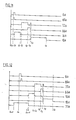
- FIG. 11 In the diagram of FIG. 11 is represented the flowchart of operation of the installation, that is to say the various diagrams of operation of the organs of this installation, as has just been described and each diagram is designated by the reference of the body concerned to which the index has been added a.
- the operating time from t5 to t6 of the fan 18 has been set at 3 minutes, considering that this operating time is sufficient, in particular when the fan 18 is equipped with an element heating.
- FIG. 12 shows another flow diagram of the operation of the installation which can be obtained in this installation to better control its operation.
- This flowchart in which the different diagrams of the different organs are designated by the same references as in FIG. 11, provides for an additional organ not previously mentioned.
- an opto-electronic cell arranged so as to detect the presence of a user placed less than a meter from the installation, for example by reflection of an infrared signal.
- This cell can also be used to overcome the drawback of a user who forgets to act on the control button 6 for starting up the installation, so that the detection of the departure of this user would control by itself the start of the entire cycle, including the opening of the solenoid valve 69 which controls the operation of the flush.
- this installation is also equipped with a manual flush control lever which, in such a circumstance, controls its operation in place of the solenoid valve 69.
- casings for protecting the chains 13, 28 and 30 as well as means making it possible to adjust the tension of the chains 28 and 30, for example by mounting the axle.
- the motor 16 is advantageously a geared motor with mechanical brake and the means for adjusting the play of the chains 13, 28 and 30 help to allow precise positioning of the flap 2 deposited on the bowl 1.
- a high pressure pump could also be provided to bring the water to the watering boom and at this time the filling of the flush can be carried out simultaneously with cleaning.
Landscapes
- Health & Medical Sciences (AREA)
- Public Health (AREA)
- Sanitary Device For Flush Toilet (AREA)
- Apparatus For Disinfection Or Sterilisation (AREA)
- Toilet Supplies (AREA)
- Cleaning By Liquid Or Steam (AREA)
- Drying Of Solid Materials (AREA)
Priority Applications (1)
| Application Number | Priority Date | Filing Date | Title |
|---|---|---|---|
| AT87420188T ATE46255T1 (de) | 1986-07-11 | 1987-07-02 | Toilette mit vorrichtung zum waschen, desinfizieren und trocknen der sitze der toilettenschuessel. |
Applications Claiming Priority (2)
| Application Number | Priority Date | Filing Date | Title |
|---|---|---|---|
| FR8610714A FR2601402B1 (fr) | 1986-07-11 | 1986-07-11 | Installation d'aisances avec dispositif de lavage, desinfection et sechage des abattants de la cuvette d'aisances. |
| FR8610714 | 1986-07-11 |
Publications (2)
| Publication Number | Publication Date |
|---|---|
| EP0252861A1 true EP0252861A1 (de) | 1988-01-13 |
| EP0252861B1 EP0252861B1 (de) | 1989-09-13 |
Family
ID=9337683
Family Applications (1)
| Application Number | Title | Priority Date | Filing Date |
|---|---|---|---|
| EP87420188A Expired EP0252861B1 (de) | 1986-07-11 | 1987-07-02 | Toilette mit Vorrichtung zum Waschen, Desinfizieren und Trocknen der Sitze der Toilettenschüssel |
Country Status (10)
| Country | Link |
|---|---|
| US (1) | US4853982A (de) |
| EP (1) | EP0252861B1 (de) |
| JP (1) | JPS6389131A (de) |
| AT (1) | ATE46255T1 (de) |
| AU (1) | AU594545B2 (de) |
| CA (1) | CA1312176C (de) |
| DE (1) | DE3760543D1 (de) |
| ES (1) | ES2010715B3 (de) |
| FR (1) | FR2601402B1 (de) |
| GR (1) | GR3000191T3 (de) |
Cited By (1)
| Publication number | Priority date | Publication date | Assignee | Title |
|---|---|---|---|---|
| CN113423439A (zh) * | 2019-02-08 | 2021-09-21 | 赛克莱恩公司 | 用于清洁和/或消毒中空管,特别是门把手杆的系统 |
Families Citing this family (15)
| Publication number | Priority date | Publication date | Assignee | Title |
|---|---|---|---|---|
| US5119517A (en) * | 1990-08-10 | 1992-06-09 | Chang Hsu S | Toilet sanitizing device |
| USD331451S (en) | 1990-12-21 | 1992-12-01 | Pierre Bourgeois | Combined toilet and toilet seat cleaning unit |
| USD358201S (en) | 1993-03-16 | 1995-05-09 | Cws International Ag | Combined toilet and toilet seat cleaning unit |
| KR100454811B1 (ko) * | 2001-11-27 | 2004-11-05 | (주) 지엔티 | 좌변기용 좌대의 살균 시스템 |
| KR100467911B1 (ko) * | 2002-04-11 | 2005-01-24 | (주) 지엔티 | 좌변기용 시트의 자동 살균 세척 시스템 |
| US7171700B2 (en) * | 2004-03-01 | 2007-02-06 | Exeloo Limited | Automatic toilet |
| WO2006022684A1 (en) * | 2004-08-04 | 2006-03-02 | Roelof Remijn | Multifunctional toilet with locking access doors |
| KR101041778B1 (ko) | 2009-03-02 | 2011-06-17 | 봉덕수 | 시트 세척기가 구비된 양변기 |
| WO2011138798A1 (en) | 2010-05-03 | 2011-11-10 | Alok Vijaykumar Pandey | Automatic retractable self-cleaning assembly for conventional toilet pots. |
| US10894103B2 (en) | 2014-11-06 | 2021-01-19 | Sensor Electronic Technology, Inc. | Ultraviolet-based bathroom surface sanitization |
| US10369239B2 (en) * | 2014-11-06 | 2019-08-06 | Sensor Electronic Technology, Inc. | Ultraviolet-based bathroom surface sanitization |
| DE102017001775A1 (de) * | 2017-02-20 | 2018-08-23 | Armin Rühle | Spül- und Reinigungssystem und Spülverfahren für eine Toilette |
| US10669706B2 (en) | 2018-04-20 | 2020-06-02 | 3S Renovations, LLC | Toilet assemblies |
| WO2020231844A1 (en) | 2019-05-10 | 2020-11-19 | F Squared Tech, Inc. | Hydraulic system including manifold, flush valve, and shut off |
| RU2725497C1 (ru) * | 2020-03-06 | 2020-07-02 | Александр Аркадьевич Клиндюк | Устройство автоматической мойки и дезинфекции сиденья унитаза |
Citations (2)
| Publication number | Priority date | Publication date | Assignee | Title |
|---|---|---|---|---|
| EP0092481A1 (de) * | 1982-04-16 | 1983-10-26 | Martinval, André | Toilettenanlage (W.C) |
| FR2543594A1 (fr) * | 1983-03-30 | 1984-10-05 | Dev Distr Ste Fse | Dispositif de fourniture et nettoyage d'abattants pour cuvette d'aisance |
Family Cites Families (8)
| Publication number | Priority date | Publication date | Assignee | Title |
|---|---|---|---|---|
| US1877689A (en) * | 1931-06-13 | 1932-09-13 | Electric Steam Generators Inc | Toilet seat sterilizer |
| CH512229A (de) * | 1970-07-17 | 1971-09-15 | W Schnyder Conrad | Einrichtung zum selbsttätigen Reinigen einer Klosett-Sitzfläche nach Gebrauch |
| FR2344261A2 (fr) * | 1976-03-18 | 1977-10-14 | Vivier Harry | Assainisseur-echangeur d'ecrans de proprete pour cuvette d'aisance |
| FR2499124A1 (fr) * | 1981-02-05 | 1982-08-06 | Sato Associes | Unite sanitaire comportant des moyens de nettoyage |
| FR2571951B1 (fr) * | 1984-10-19 | 1988-04-08 | Blanchard Claude | Siege de cabinets a dispositif de nettoyage automatique de la lunette |
| US4692951A (en) * | 1984-10-31 | 1987-09-15 | Toto Ltd. | Sanitary facility room for clean room |
| FR2580310B1 (fr) * | 1985-04-11 | 1987-06-19 | Nelva Pasqual Yves | Dispositif de nettoyage pour le siege d'une cuvette de cabinet d'aisances |
| IE58641B1 (en) * | 1985-10-14 | 1993-10-20 | Cws Ag | Device for the automatic cleaning of a toilet seat |
-
1986
- 1986-07-11 FR FR8610714A patent/FR2601402B1/fr not_active Expired
-
1987
- 1987-07-02 ES ES87420188T patent/ES2010715B3/es not_active Expired
- 1987-07-02 DE DE8787420188T patent/DE3760543D1/de not_active Expired
- 1987-07-02 EP EP87420188A patent/EP0252861B1/de not_active Expired
- 1987-07-02 AT AT87420188T patent/ATE46255T1/de not_active IP Right Cessation
- 1987-07-07 US US07/071,547 patent/US4853982A/en not_active Expired - Fee Related
- 1987-07-10 JP JP62171363A patent/JPS6389131A/ja active Pending
- 1987-07-10 CA CA000541822A patent/CA1312176C/fr not_active Expired - Fee Related
- 1987-12-14 AU AU82501/87A patent/AU594545B2/en not_active Ceased
-
1989
- 1989-10-24 GR GR89400212T patent/GR3000191T3/el unknown
Patent Citations (2)
| Publication number | Priority date | Publication date | Assignee | Title |
|---|---|---|---|---|
| EP0092481A1 (de) * | 1982-04-16 | 1983-10-26 | Martinval, André | Toilettenanlage (W.C) |
| FR2543594A1 (fr) * | 1983-03-30 | 1984-10-05 | Dev Distr Ste Fse | Dispositif de fourniture et nettoyage d'abattants pour cuvette d'aisance |
Cited By (2)
| Publication number | Priority date | Publication date | Assignee | Title |
|---|---|---|---|---|
| CN113423439A (zh) * | 2019-02-08 | 2021-09-21 | 赛克莱恩公司 | 用于清洁和/或消毒中空管,特别是门把手杆的系统 |
| CN113423439B (zh) * | 2019-02-08 | 2023-09-08 | 赛克莱恩公司 | 用于清洁和/或消毒中空管,特别是门把手杆的系统 |
Also Published As
| Publication number | Publication date |
|---|---|
| ATE46255T1 (de) | 1989-09-15 |
| EP0252861B1 (de) | 1989-09-13 |
| FR2601402A1 (fr) | 1988-01-15 |
| US4853982A (en) | 1989-08-08 |
| DE3760543D1 (en) | 1989-10-19 |
| FR2601402B1 (fr) | 1988-11-25 |
| CA1312176C (fr) | 1993-01-05 |
| JPS6389131A (ja) | 1988-04-20 |
| GR3000191T3 (en) | 1990-12-31 |
| ES2010715B3 (es) | 1989-12-01 |
| AU8250187A (en) | 1989-06-15 |
| AU594545B2 (en) | 1990-03-08 |
Similar Documents
| Publication | Publication Date | Title |
|---|---|---|
| EP0252861B1 (de) | Toilette mit Vorrichtung zum Waschen, Desinfizieren und Trocknen der Sitze der Toilettenschüssel | |
| EP0209474A1 (de) | Toilette für Hunde und Katzen | |
| EP0179725B1 (de) | Klosettsitz mit automatischer Reinigungsvorrichtung der Brille | |
| EP0005660A1 (de) | Vorrichtung zum Verpacken von Gegenständen in einem durchgehenden Schlauch und einen positiven Mechanismus zum Antrieb dieses Schlauches umfassend | |
| EP0242274A1 (de) | Sanitäreinheit mit automatischer Reinigung | |
| EP2681992B1 (de) | Sanitärvorrichtung für Haustiere | |
| EP0356292B1 (de) | Sanitärmodul zur automatischen Reinigung mit drehbarer Rückenlehne | |
| EP0262275B1 (de) | Vorrichtung zum Säubern eines Klosettsitzes | |
| CH638854A5 (fr) | Bloc sanitaire comportant un receptacle monte mobile entre une position d'utilisation et une position de nettoyage. | |
| FR2617008A1 (fr) | Caisse d'aisance pour animaux domestiques avec separation automatique des dejections solides de la litiere | |
| FR2744743A1 (fr) | Installation d'aisance a nettoyage automatique de la cuvette | |
| EP1138241B1 (de) | Sanitäreinheit mit Toilettenreinigung | |
| EP0330553A1 (de) | Spender für aufgerolltes hygienisches Handtuchband | |
| EP1653017B1 (de) | Sanitärmodul zur automatischen Reinigung mit drehbarer Klosettschüssel und Rückenlehne | |
| EP0201435B1 (de) | Toiletteneinrichtung mit Vorrichtung zum Reinigen des Sitzes der Toilettenschüssel und Toilettenschüssel zum Gebrauch dieser Einrichtung | |
| WO2020084092A1 (fr) | Balayeuse pourvue d'un dispositif de decolmatage de son filtre a air | |
| EP0921239B1 (de) | Toiletteneinrichtung mit automatischer Reinigung und einer translatorisch bewegbaren Toilettenschüssel und sein Reinigungsverfahren | |
| FR2543594A1 (fr) | Dispositif de fourniture et nettoyage d'abattants pour cuvette d'aisance | |
| CH613376A5 (en) | Toilet installation | |
| CA1231870A (fr) | Ilot d'hygiene, pour chiens notamment | |
| FR3066774A1 (fr) | Systeme de rangement d'un volet de protection pour une piscine dans un coffre dote d'un couvercle articule | |
| EP0959186B1 (de) | Automatische Wasserspülung | |
| FR2761253A1 (fr) | Cabinet d'aisance muni d'un dispositif escamotable de nettoyage de la lunette | |
| FR2746583A1 (fr) | Appareil sanitaire pour animaux domestiques | |
| CH665866A5 (fr) | Dispositif de nettoyage automatique d'une lunette de wc. |
Legal Events
| Date | Code | Title | Description |
|---|---|---|---|
| PUAI | Public reference made under article 153(3) epc to a published international application that has entered the european phase |
Free format text: ORIGINAL CODE: 0009012 |
|
| AK | Designated contracting states |
Kind code of ref document: A1 Designated state(s): AT BE CH DE ES FR GB GR IT LI LU NL SE |
|
| 17P | Request for examination filed |
Effective date: 19871221 |
|
| 17Q | First examination report despatched |
Effective date: 19880823 |
|
| GRAA | (expected) grant |
Free format text: ORIGINAL CODE: 0009210 |
|
| AK | Designated contracting states |
Kind code of ref document: B1 Designated state(s): AT BE CH DE ES FR GB GR IT LI LU NL SE |
|
| REF | Corresponds to: |
Ref document number: 46255 Country of ref document: AT Date of ref document: 19890915 Kind code of ref document: T |
|
| ITF | It: translation for a ep patent filed | ||
| REF | Corresponds to: |
Ref document number: 3760543 Country of ref document: DE Date of ref document: 19891019 |
|
| GBT | Gb: translation of ep patent filed (gb section 77(6)(a)/1977) | ||
| REG | Reference to a national code |
Ref country code: GR Ref legal event code: FG4A Free format text: 3000191 |
|
| PLBE | No opposition filed within time limit |
Free format text: ORIGINAL CODE: 0009261 |
|
| STAA | Information on the status of an ep patent application or granted ep patent |
Free format text: STATUS: NO OPPOSITION FILED WITHIN TIME LIMIT |
|
| 26N | No opposition filed | ||
| ITTA | It: last paid annual fee | ||
| PGFP | Annual fee paid to national office [announced via postgrant information from national office to epo] |
Ref country code: GB Payment date: 19940630 Year of fee payment: 8 |
|
| EPTA | Lu: last paid annual fee | ||
| EAL | Se: european patent in force in sweden |
Ref document number: 87420188.2 |
|
| PG25 | Lapsed in a contracting state [announced via postgrant information from national office to epo] |
Ref country code: GB Effective date: 19950702 |
|
| GBPC | Gb: european patent ceased through non-payment of renewal fee |
Effective date: 19950702 |
|
| PGFP | Annual fee paid to national office [announced via postgrant information from national office to epo] |
Ref country code: FR Payment date: 19980630 Year of fee payment: 12 |
|
| PGFP | Annual fee paid to national office [announced via postgrant information from national office to epo] |
Ref country code: GR Payment date: 19980707 Year of fee payment: 12 |
|
| PGFP | Annual fee paid to national office [announced via postgrant information from national office to epo] |
Ref country code: SE Payment date: 19980709 Year of fee payment: 12 |
|
| PGFP | Annual fee paid to national office [announced via postgrant information from national office to epo] |
Ref country code: ES Payment date: 19980715 Year of fee payment: 12 |
|
| PGFP | Annual fee paid to national office [announced via postgrant information from national office to epo] |
Ref country code: LU Payment date: 19980724 Year of fee payment: 12 |
|
| PGFP | Annual fee paid to national office [announced via postgrant information from national office to epo] |
Ref country code: BE Payment date: 19980729 Year of fee payment: 12 |
|
| PGFP | Annual fee paid to national office [announced via postgrant information from national office to epo] |
Ref country code: DE Payment date: 19980730 Year of fee payment: 12 Ref country code: AT Payment date: 19980730 Year of fee payment: 12 |
|
| PGFP | Annual fee paid to national office [announced via postgrant information from national office to epo] |
Ref country code: NL Payment date: 19980731 Year of fee payment: 12 |
|
| PGFP | Annual fee paid to national office [announced via postgrant information from national office to epo] |
Ref country code: CH Payment date: 19981015 Year of fee payment: 12 |
|
| PG25 | Lapsed in a contracting state [announced via postgrant information from national office to epo] |
Ref country code: LU Free format text: LAPSE BECAUSE OF NON-PAYMENT OF DUE FEES Effective date: 19990702 Ref country code: AT Free format text: LAPSE BECAUSE OF NON-PAYMENT OF DUE FEES Effective date: 19990702 |
|
| PG25 | Lapsed in a contracting state [announced via postgrant information from national office to epo] |
Ref country code: SE Free format text: THE PATENT HAS BEEN ANNULLED BY A DECISION OF A NATIONAL AUTHORITY Effective date: 19990703 Ref country code: ES Free format text: LAPSE BECAUSE OF NON-PAYMENT OF DUE FEES Effective date: 19990703 |
|
| PG25 | Lapsed in a contracting state [announced via postgrant information from national office to epo] |
Ref country code: LI Free format text: LAPSE BECAUSE OF NON-PAYMENT OF DUE FEES Effective date: 19990731 Ref country code: GR Free format text: LAPSE BECAUSE OF NON-PAYMENT OF DUE FEES Effective date: 19990731 Ref country code: FR Free format text: THE PATENT HAS BEEN ANNULLED BY A DECISION OF A NATIONAL AUTHORITY Effective date: 19990731 Ref country code: CH Free format text: LAPSE BECAUSE OF NON-PAYMENT OF DUE FEES Effective date: 19990731 Ref country code: BE Free format text: LAPSE BECAUSE OF NON-PAYMENT OF DUE FEES Effective date: 19990731 |
|
| BERE | Be: lapsed |
Owner name: MARTINVAL ANDRE Effective date: 19990731 |
|
| PG25 | Lapsed in a contracting state [announced via postgrant information from national office to epo] |
Ref country code: NL Free format text: LAPSE BECAUSE OF NON-PAYMENT OF DUE FEES Effective date: 20000201 |
|
| REG | Reference to a national code |
Ref country code: CH Ref legal event code: PL |
|
| EUG | Se: european patent has lapsed |
Ref document number: 87420188.2 |
|
| NLV4 | Nl: lapsed or anulled due to non-payment of the annual fee |
Effective date: 20000201 |
|
| PG25 | Lapsed in a contracting state [announced via postgrant information from national office to epo] |
Ref country code: DE Free format text: LAPSE BECAUSE OF NON-PAYMENT OF DUE FEES Effective date: 20000503 |
|
| REG | Reference to a national code |
Ref country code: FR Ref legal event code: ST |
|
| REG | Reference to a national code |
Ref country code: ES Ref legal event code: FD2A Effective date: 20000810 |
|
| PG25 | Lapsed in a contracting state [announced via postgrant information from national office to epo] |
Ref country code: IT Free format text: LAPSE BECAUSE OF NON-PAYMENT OF DUE FEES;WARNING: LAPSES OF ITALIAN PATENTS WITH EFFECTIVE DATE BEFORE 2007 MAY HAVE OCCURRED AT ANY TIME BEFORE 2007. THE CORRECT EFFECTIVE DATE MAY BE DIFFERENT FROM THE ONE RECORDED. Effective date: 20050702 |