EP0252996B1 - Vorrichtung zur filtration einer fluessigkeit - Google Patents
Vorrichtung zur filtration einer fluessigkeit Download PDFInfo
- Publication number
- EP0252996B1 EP0252996B1 EP87900741A EP87900741A EP0252996B1 EP 0252996 B1 EP0252996 B1 EP 0252996B1 EP 87900741 A EP87900741 A EP 87900741A EP 87900741 A EP87900741 A EP 87900741A EP 0252996 B1 EP0252996 B1 EP 0252996B1
- Authority
- EP
- European Patent Office
- Prior art keywords
- filter element
- housing
- liquid
- annular space
- hollow body
- Prior art date
- Legal status (The legal status is an assumption and is not a legal conclusion. Google has not performed a legal analysis and makes no representation as to the accuracy of the status listed.)
- Expired - Lifetime
Links
- 239000007788 liquid Substances 0.000 title claims abstract description 36
- 238000001914 filtration Methods 0.000 title claims abstract description 32
- 239000000463 material Substances 0.000 claims 1
- 239000002244 precipitate Substances 0.000 abstract 2
- 238000009825 accumulation Methods 0.000 abstract 1
- 239000000945 filler Substances 0.000 description 8
- 238000004140 cleaning Methods 0.000 description 6
- 239000004744 fabric Substances 0.000 description 6
- 238000000034 method Methods 0.000 description 3
- 231100000614 poison Toxicity 0.000 description 3
- 239000003440 toxic substance Substances 0.000 description 3
- 238000006073 displacement reaction Methods 0.000 description 2
- 239000000126 substance Substances 0.000 description 2
- 238000004026 adhesive bonding Methods 0.000 description 1
- 238000011109 contamination Methods 0.000 description 1
- 230000008878 coupling Effects 0.000 description 1
- 238000010168 coupling process Methods 0.000 description 1
- 238000005859 coupling reaction Methods 0.000 description 1
- 230000007423 decrease Effects 0.000 description 1
- 238000007599 discharging Methods 0.000 description 1
- 239000003651 drinking water Substances 0.000 description 1
- 235000020188 drinking water Nutrition 0.000 description 1
- 230000002349 favourable effect Effects 0.000 description 1
- 239000000835 fiber Substances 0.000 description 1
- 238000011010 flushing procedure Methods 0.000 description 1
- 239000010842 industrial wastewater Substances 0.000 description 1
- 244000144972 livestock Species 0.000 description 1
- 238000012856 packing Methods 0.000 description 1
- 238000005192 partition Methods 0.000 description 1
- 238000000746 purification Methods 0.000 description 1
- 230000001105 regulatory effect Effects 0.000 description 1
- 239000004576 sand Substances 0.000 description 1
- 239000010802 sludge Substances 0.000 description 1
- 239000007787 solid Substances 0.000 description 1
Images


Classifications
-
- B—PERFORMING OPERATIONS; TRANSPORTING
- B01—PHYSICAL OR CHEMICAL PROCESSES OR APPARATUS IN GENERAL
- B01D—SEPARATION
- B01D29/00—Filters with filtering elements stationary during filtration, e.g. pressure or suction filters, not covered by groups B01D24/00 - B01D27/00; Filtering elements therefor
- B01D29/11—Filters with filtering elements stationary during filtration, e.g. pressure or suction filters, not covered by groups B01D24/00 - B01D27/00; Filtering elements therefor with bag, cage, hose, tube, sleeve or like filtering elements
- B01D29/13—Supported filter elements
- B01D29/23—Supported filter elements arranged for outward flow filtration
- B01D29/27—Filter bags
-
- B—PERFORMING OPERATIONS; TRANSPORTING
- B01—PHYSICAL OR CHEMICAL PROCESSES OR APPARATUS IN GENERAL
- B01D—SEPARATION
- B01D29/00—Filters with filtering elements stationary during filtration, e.g. pressure or suction filters, not covered by groups B01D24/00 - B01D27/00; Filtering elements therefor
- B01D29/62—Regenerating the filter material in the filter
- B01D29/64—Regenerating the filter material in the filter by scrapers, brushes, nozzles, or the like, acting on the cake side of the filtering element
-
- B—PERFORMING OPERATIONS; TRANSPORTING
- B01—PHYSICAL OR CHEMICAL PROCESSES OR APPARATUS IN GENERAL
- B01D—SEPARATION
- B01D29/00—Filters with filtering elements stationary during filtration, e.g. pressure or suction filters, not covered by groups B01D24/00 - B01D27/00; Filtering elements therefor
- B01D29/62—Regenerating the filter material in the filter
- B01D29/70—Regenerating the filter material in the filter by forces created by movement of the filter element
-
- B—PERFORMING OPERATIONS; TRANSPORTING
- B01—PHYSICAL OR CHEMICAL PROCESSES OR APPARATUS IN GENERAL
- B01D—SEPARATION
- B01D29/00—Filters with filtering elements stationary during filtration, e.g. pressure or suction filters, not covered by groups B01D24/00 - B01D27/00; Filtering elements therefor
- B01D29/88—Filters with filtering elements stationary during filtration, e.g. pressure or suction filters, not covered by groups B01D24/00 - B01D27/00; Filtering elements therefor having feed or discharge devices
- B01D29/90—Filters with filtering elements stationary during filtration, e.g. pressure or suction filters, not covered by groups B01D24/00 - B01D27/00; Filtering elements therefor having feed or discharge devices for feeding
Definitions
- the invention relates to a filter device for filtering a liquid, with a housing, with a tubular filter element, which can be put over to form an annular space, which is connected at one end to a drive roller arranged above the filter element and with the inside of its other end on the circumference of one in the housing arranged hollow body is attached, which forms an annular space with the housing, with a feed device for supplying a liquid to be filtered and a discharge device for discharging a cleaned liquid, each of which is connected to the housing and with a discharge device for a Residue discharge, which is connected to the annular space.
- Such a filter device known from CH-A-500747 has an outer, conical and permeable housing part and a cylindrical and permeable inner housing part arranged concentrically therein. Between these housing parts, a tubular filter cloth is arranged as a filter element, the edges of which are fastened to the upper ends of the two housing parts. In its filtering position, this filter device is closed by a cover flange. The medium to be filtered is fed into the annular space formed by the filter cloth via feed lines passing through the cover flange and filtered through the filter cloth until the annular space is filled with residue. The efficiency of the filtering is constantly reduced, since the filter area becomes smaller as the residue increases.
- the cover flange lifted together with the inner housing part by an outer lifting device, as a result of which the filter cloth is stretched and is accessible from the outside for its cleaning. Since the filter cloth of this filter device is quickly blocked, frequent cleaning of the filter cloth is necessary. The efficiency of this filter device is therefore low. In addition, no strong smelling or toxic substances can be filtered with this filter device, since they can escape to the outside both during filtration and during cleaning.
- the invention has for its object to provide a filter device with structurally simple means with which substances with a strong smell or toxic substances can be filtered safely with high efficiency.
- the housing is closed and pressure-tight, that the hollow body is cylindrical and that the drive roller is arranged within the housing and its torque can be regulated so that the filter element is lowered when a desired pressure of the liquid is reached becomes.
- the pressure-tight design of the housing enables substances with a strong odor or toxic substances to be filtered safely.
- the efficiency of the filter device can be increased if an increased pressure is generated in the space above the filter element and a negative pressure is generated in the space below the filter element. Because the lifting device is arranged inside the housing, the filter element can be moved during the filtering process, depending on the amount of residue, so that a clean filtering surface is constantly available. This additionally increases the efficiency of the filter device.
- the filter element is expediently attached to the outer surface of the cylindrical hollow body.
- the outer surface of the cylindrical hollow body has through holes and the cylindrical hollow body is connected to the feed device.
- a container is arranged in the lower region of the housing, which is connected via pipes to the upper region of the housing, in which a guide channel is arranged in such a way that a filler emerging from the pipes passes through it Annulus is poured.
- a further advantageous embodiment has an inflatable elastic hollow ring arranged in the cylindrical hollow body at the level of the attachment of the other end of the filter element.
- the filter device can be used for desludging industrial wastewater, for cleaning sewer drains and for cleaning circulating and drinking water. It can also be used to separate runoff from livestock farms into a solid and a liquid fraction and to separate digested sludge from sewer and pool cleaning.
- the periodically acting filter device for filtering a liquid shown in FIGS. 1 to 5 has a pressure-tightly closed housing 1, which has a check device 2 with a feed device 3 for supplying a liquid to be filtered (filter liquid) via a valve 4 a discharge device 5 for the discharge of residues and via a valve 6 with a discharge device 7 for the discharge of a cleaned liquid.
- a hollow cylinder 8 which forms with the housing 1 an annular space 9 connected to the discharge device 5, and a flexible tubular filter element 10 are arranged.
- the filter element 10 With one end 11, the filter element 10 is fastened to a drive drum 12 arranged in the upper part of the housing 1, while its other end 13 is turned inside out and fastened along the circumference to the hollow cylinder 8, whereby an annular space 14 around the remaining section of the Filter element 10 is formed, in which the filtering liquid is fed for filtering.
- the annular space 14 changes its volume during the storage of the residue and the displacement of the filter element by the drive drum 12.
- the end 13 of the filter element 10, which is turned inside out, is fastened to the open end of the hollow cylinder 8 and lowered into the cylinder space.
- the annular space 14 increases under the influence of the residue stored therein or decreases as the filter element 10 moves upward in the hollow cylinder 8.
- the hollow area of the hollow cylinder 8 is in its lower region with the discharge device 7 for cleaned liquid in connection.
- the end 13 of the filter element 10 is attached to the outer surface of the hollow cylinder 8, for example by gluing, or fastening parts, etc.
- the end 11 of the filter element 10 can be attached directly to the drive drum 12 or to a rigid ring 16 (FIGS. 2 to 5), to which cables 17 wound on the drive drum 12 are attached.
- a reversing drive For the rotation of the drive drum 12, a reversing drive is used, which has an electric motor (not shown) and a clutch (not shown) for lifting and, if necessary, lowering the filter element 10, which coupling is coupled to the shaft of the drive drum 12.
- the drive drum 12 is provided with a device 18 which regulates its torque depending on the set pressure which is exerted on the filter element 10 by the filtering liquid and the residue located in the annular space 14 of the filter element 10.
- a ratchet or friction lock can serve as such a device.
- the filter element 10 can move during the filtration process either in the cavity 19 of the hollow cylinder 8 (FIG. 1), or over its outer surface (FIGS. 2 to 5) in the annular space 9 of the housing 1.
- the filter element 10 is guided over the outer surface of the hollow cylinder 8 when the filter residue is removed from the annular space 14, the end 11 coming to rest in the lower part of the housing, as shown in FIGS. 3 and 5.
- the filter liquid can be supplied via the hollow cylinder 8, as shown in FIGS. 2 to 5.
- the feed device 3 is accommodated in the cavity 19 of the hollow cylinder 8.
- the cavity 19 is divided into sections by partitions 20 (FIGS. 4, 5).
- Through holes 21 are provided in the hollow cylinder 8 for the outflow of the filter liquid.
- a sleeve 22 is arranged in the annular space 14 (FIGS. 2, 3) of the filter element 10 coaxially with the hollow cylinder 8. With regard to the hollow cylinder 8 and the end 13 of the filter element 10 fastened thereon, the sleeve 22 is arranged with a clearance 23, as a result of which it can move along the hollow cylinder 8 together with the filter element 10. To limit the displacement of the sleeve 22, a ring stop 24 is provided on the hollow cylinder 8 and a collar 25 on the sleeve 22.
- the liquid can be filtered using a pourable filler such as sand, gravel, packing, fibers, etc.
- a container 26 (FIGS. 4, 5) connected to the discharge device 5 is provided in the lower part of the housing 1 in the filter device.
- the lower part of this container 26 is connected to the upper part of the housing 1 via pipes 27 provided with overflow valves.
- the filler (filter medium) is fed through the tubes 27 in any known manner to the upper part of the housing 1, where it is guided into the annular space 14 of the filter element 10 via a guide channel 28.
- a flexible sleeve 29, for example made of rubber, is provided, which is attached to the hollow cylinder 8 and covers the inflow opening of the container 26. Due to its elasticity, the sleeve 29 presses against the hollow cylinder 10 under the action of the filter element 10 which turns inside out with filler and liquid, as a result of which the end 11 of the filter element 10 sinks freely and spills the filler and residue into the container 26 can. After the hose has moved upward into the starting position, the sleeve 29 restores its shape.
- the filter device is provided with a device which, after filtering, turns the tubular filter element 10 inside out over the outside of the hollow cylinder 8, as a result of which the residue is most completely removed from the filter surface and the surface of the Filter element 10 can be rinsed.
- This device consists of an elastic hollow ring 30, which is arranged in the cavity of the hollow cylinder 8 at the level of the attachment of the filter element 10 and is connected to a compressed air system 31 by means of a flexible hose 32.
- the hollow ring 30 increases in size and covers the hollow cylinder 8, as a result of which the filter element 10, which has been provisionally raised to the position indicated by the dotted line, is guided over the outer surface of the hollow cylinder 8, the flexible hose 32 displacing the filter element 10 does not hinder.
- the filter-tight housing 1 With the feed device 3, the filter-tight housing 1 is supplied with the filtering liquid, which flows into the annular space 14 of the tubular filter element 10 and is filtered through the filter element 10, while the residue remains in the annular space 14.
- the cleaned liquid flows into the discharge device 7.
- the residue and the filter liquid collect in the annular space 14.
- the device 18 responds, causing the Drive drum 12 rotates and the contaminated surface portion of the filter element 10 goes down and migrates to the inner surface of the hollow cylinder 8.
- a clean surface of the filter element 10 thus enters the filtration zone, as a result of which the volume of the annular space 14 of the filter element 10 is increased.
- the drive of the drive drum 12 is switched on and the filter element 10 is wound onto the drive drum 12.
- compressed air is conveyed into the elastic hollow ring 30, which inflates it so that it covers the cavity of the hollow cylinder 8.
- the filter element 10 is then lowered by switching the drum drive. Under the action of the residue on its surface, the filter element 10 sinks along the outer surface of the hollow cylinder 8 and turns inside out, so that the end 11 of the filter element 10 comes to rest in the lower part of the housing 1.
- the residue is located on the open side of the filter element 10.
- the filtering or rinsing liquid Under the action of the filtering or rinsing liquid, the residue is washed away from the surface of the filter element 10 and fed to the discharge device 5.
- the drive drum 12 After the filter element has been rinsed, the drive drum 12 begins to rotate in the opposite direction and the filter element 10 is wound up. After the upward movement of the filter element 10, air is released from the elastic hollow ring 30 and the filter element 10 is lowered into the cavity 19 of the hollow cylinder 8. The filtration cycle is repeated.
- the filter liquid flows from the feed device 3 through a nozzle 33 arranged in the hollow cylinder 8 through the annular gap 23 between the sleeve 22 and the end 13 of the filter element 10 fastened to the outside of the hollow cylinder 8 and into the annular space 14 and is filtered by the filter element 10, the clean portions of the filter element 10 during the filtering process just as in the embodiment 1 are supplied.
- the valve 6 has closed and the end 11 of the filter element 10 with the ring 16 has been brought into the lower end position, ie after the filter element 10 has turned completely inside out on the outer surface of the hollow cylinder 8 (FIG.
- valve 4 opens, and the liquid flows with the residue into the discharge device 5, the filtering or rinsing liquid jets rinsing the residue away from the surface of the filter element 10 as it flows through the annular gap 23.
- valve 4 closes and valve 6 opens.
- the drive drum 12 begins to rotate in the opposite direction, whereby the end 11 of the filter element 10 together with the sleeve 22 moves upward.
- the annular space 14 forms again and increases its volume.
- the filter liquid is returned to the annular space 14. The filtration cycle is repeated.
- the filter device of FIGS. 4 and 5 functions in exactly the same way as the filter devices of FIGS. 2 and 3. Simultaneously with the lowering of the end 11 and the turning of the filter element 10 over the outer surface of the hollow cylinder 8, the sleeve 29 presses against the hollow cylinder 8 the annular space 14, the filler and the residue are poured into the container 26. The filtering or rinsing liquid flows through the filter element 10 and cleans it through the through bores 21 in the lower part of the hollow cylinder 8. The end 11 of the filter element 10 is then raised into the starting position by the rotation of the drive drum 12, as shown in FIG. 4. The residue is passed together with the liquid into the discharge device 5.
- the cleaned filler is fed via the pipes 27 to the upper part of the housing 1 and poured into the annular space 14 via the guide channel 28.
- the medium to be filtered flows into the annular space 14 through the bores 21 in the upper part of the cylinder, flows through the filler and the filter element and is fed through the casing 29 to the discharge device 7.
Landscapes
- Chemical & Material Sciences (AREA)
- Chemical Kinetics & Catalysis (AREA)
- Filtration Of Liquid (AREA)
- Nitrogen And Oxygen Or Sulfur-Condensed Heterocyclic Ring Systems (AREA)
- Electrical Discharge Machining, Electrochemical Machining, And Combined Machining (AREA)
- Fittings On The Vehicle Exterior For Carrying Loads, And Devices For Holding Or Mounting Articles (AREA)
Description
- Die Erfindung betrifft eine Filtervorrichtung zum Filtern einer Flüssigkeit, mit einem Gehäuse, mit einem schlauchförmigen, unter Bildung eines Ringraums stülpbaren Filterelement, das mit seinem einen Ende mit einer oberhalb des Filterelements angeordneten Antriebsrolle verbunden ist und mit der Innenseite seines anderen Endes am Umfang eines in dem Gehäuse angeordneten Hohlkörpers befestigt ist, der mit dem Gehäuse einen ringförmigen Zwischenraum bildet, mit einer Zuführeinrichtung für eine Zuführung einer zu filternden Flüssigkeit und einer Ableiteinrichtung für ein Ableiten einer gereinigten Flüssigkeit, die jeweils mit dem Gehäuse in Verbindung stehen und mit einer Abführeinrichtung für eine Rückstandsabführung, die mit dem ringförmigen Zwischenraum verbunden ist.
- Eine solche, aus der CH-A-500747 bekannte Filtervorrichtung weist einen äußeren, konischen und durchlässigen Gehäuseteil und einen in diesem konzentrisch angeordneten, zylindrischen und durchlässigen inneren Gehäuseteil auf. Zwischen diesen Gehäuseteilen ist als Filterelement ein schlauchförmiges Filtertuch angeordnet, dessen Ränder an den oberen Enden der beiden Gehäuseteile befestigt sind. Diese Filtervorrichtung ist in ihrer Filtrierstellung durch einen Deckflansch verschlossen. Das zu filtrierende Medium wird über durch den Deckflansch hindurchgehende Zuführleitungen in den von dem Filtertuch gebildeten Ringraum solange geführt und durch das Filtertuch gefiltert, bis der Ringraum mit Rückstand gefüllt ist. Dabei wird der Wirkungsgrad der Filterung ständig geringer, da die Filterfläche mit größer werdendem Rückstand kleiner wird. Nach Abschluß einer Filterperiode wird der Deckflansch zusammen mit dem inneren Gehäuseteil durch eine äußere Hebevorrichtung angehoben, wodurch das Filtertuch gestreckt und für seine Reinigung von außen zugänglich ist. Da das Filtertuch dieser Filtervorrichtung schnell verstopft ist, ist eine häufige Reinigung des Filtertuchs notwendig. Der Wirkungsgrad dieser Filtervorrichtung ist also gering. Außerdem können mit dieser Filtervorrichtung keine stark riechenden oder giftige Stoffe gefiltert werden, da sie sowohl bei der Filtrierung als auch bei der Reinigung ins Freie austreten können.
- Der Erfindung liegt die Aufgabe zugrunde, mit konstruktiv einfachen Mitteln eine Filtervorrichtung zu schaffen, mit der mit hohem Wirkungsgrad auch Stoffe mit starkem Geruch oder giftige Stoffe gefahrlos gefiltert werden können.
- Diese Aufgabe wird ausgehend vom gattungsgemäßen Stand der Technik dadurch gelöst, daß das Gehäuse geschlossen und druckdicht ist, daß der Hohlkörper zylindrisch ist und daß die Antriebsrolle innerhalb des Gehäuses angeordnet und ihr Drehmoment so regelbar ist, daß bei Erreichen eines Solldrucks der Flüssigkeit das Filterelement abgesenkt wird.
- Die druckdichte Ausführung des Gehäuses ermöglicht es, Stoffe mit starkem Geruch oder giftige Stoffe gefahrlos zu filtern. Dabei kann der Wirkungsgrad der Filtervorrichtung erhöht werden, wenn in dem Raum oberhalb des Filterelements ein erhöhter Druck und in dem Raum unterhalb des Filterelements ein Unterdruck erzeugt wird. Dadurch, daß die Hebevorrichtung innerhalb des Gehäuses angeordnet ist, kann das Filterelement während des Filtriervorgangs abhängig von der Rückstandsmenge so bewegt werden, daß ständig eine saubere Filtrierfläche zur Verfügung steht. Dies erhöht zusätzlich den Wirkungsgrad der Filtervorrichtung.
- Zweckmäßigerweise ist das Filterelement an der Außenfläche des zylindrischen Hohlkörpers befestigt.
- Für eine gute Spülung des Filterelements weist die Mantelfläche des zylindrischen Hohlkörpers Durchgangsbohrungen auf und steht der zylindrische Hohlkörper mit der Zuführeinrichtung in Verbindung.
- Es ist günstig, eine entlang des zylindrischen Hohlkörpers verschiebbare Hülse koaxial und mit Spiel zu dem zylindrischen Hohlkörper in dem Ringraum des Filterelements anzuordnen.
- Bei einer bevorzugten Ausführungsform der erfindungsgemäßen Filtervorrichtung ist im unteren Bereich des Gehäuses ein Behälter angeordnet ist, der über Rohre mit dem oberen Bereich des Gehäuses in Verbindung steht, in dem eine Leitrinne so angeordnet ist, daß durch sie ein aus den Rohren austretender Füllstoff in den Ringraum geschüttet wird.
- Eine weitere vorteilhafte Ausführungsform weist einen in dem zylindrischen Hohlkörper auf Höhe der Befestigung des anderen Endes des Filterelements angeordneten, aufblasbaren elastischen Hohlring auf.
- Die Filtervorrichtung kann zur Entschlammung von Industrieabwässsern, zur Reinigung von Kanalisationsabflüssen und zur Reinigung von Umlauf- und Trinkwasser verwendet werden. Außerdem kann sie zur Trennung von Abflüssen von Viehzuchtfarmen in eine feste und eine flüssige Fraktion sowie zur Abtrennung von Faulschlamm bei der Kanal- und Waserbeckenreinigung benutzt werden.
- Ausführungsbeispiele der Erfindung werden nachstehend anhand von Zeichnungen näher erläutert. Es zeigt:
- Fig. 1
- im Längsschnitt eine erste Ausführungsform einer Filtervorrichtung;
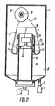
- Fig. 2
- eine zweite Ausführungsform der Filtervorrichtung;
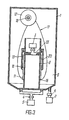
- Fig. 3
- die Filtervorrichtung von Fig. 2 mit in Spülstellung befindlichem Filterelement;
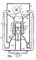
- Fig. 4
- eine dritte Ausführungsform der Filtervorrichtung;
- Fig. 5
- die Filtervorrichtung von Fig. 4 mit in Spülstellung befindlichem Filterelement.
- Die in den Fig. 1 bis 5 gezeigte, periodisch wirkende Filtervorrichtung zum Filtern einer Flüssigkeit weist ein druckdicht abgeschlossenes Gehäuse 1 auf, das über ein Rückschlagventil 2 mit einer Zuführeinrichtung 3 für die Zuführung einer zu filtrierenden Flüssigkeit, (Filtrierflüssigkeit) über ein Ventil 4 mit einer Abführeinrichtung 5 für die Rückstandsabführung und über ein Ventil 6 mit einer Ableiteinrichtung 7 für das Ableiten einer gereinigten Flüssigkeit in Verbindung steht.
- Im Gehäuse 1 sind ein Hohlzylinder 8, der mit dem Gehäuse 1 einen an die Abführeinrichtung 5 angeschlossenen ringförmigen Zwischenraum 9 bildet, und ein biegsames schlauchförmiges Filterelement 10 angeordnet.
- Mit einem Ende 11 ist das Filterelement 10 an einer im Oberteil des Gehäuses 1 angeordneten Antriebstrommel 12 befestigt, während sein anderes Ende 13 mit der Innenseite nach außen gestülpt und längs des Umfanges am Hohlzylinder 8 befestigt ist, wodurch ein Ringraum 14 um den restlichen Abschnitt des Filterelements 10 gebildet wird, in den die Filtrierflüssigkeit zur Filterung zugeführt wird.
- Durch eine derartige Befestigung der Enden des Filterelements 10 ist es relativ zu seiner Befestigungsstrecke verschiebbar. Der Ringraum 14 verändert sein Volumen während der Speicherung des darin anfallenden Rückstandes und der Verschiebung des Filterelements durch die Antriebstrommel 12.
- Gemäß Fig. 1 ist das mit der Innenseite nach außen gestülpte Ende 13 des Filterelements 10 am offenen Ende des Hohlzylinders 8 befestigt und in den Zylinderraum gesenkt. Der Ringraum 14 vergrößert sich unter dem Einfluß des darin gespeicherten Rückstandes oder verringert sich bei der Aufwärtsbewegung des Filterelements 10 im Hohlzylinder 8. Der Hohlraum des Hohlzylinders 8 steht in seinem unteren Bereich mit der Ableiteinrichtung 7 für gereinigte Flüssigkeit in Verbindung. Oberhalb des Hohlzylinders 8 ist ein Ringstutzen 15 der Zuführeinrichtung 3 angeordnet, durch den das Filterelement 10 hindurchgeführt ist.
- Das Ende 13 des Filterelements 10 ist an der Außenfläche des Hohlzylinders 8 beispielsweise durch Kleben, oder Befestigungsteile usw. befestigt.
- Das Ende 11 des Filterelements 10 kann unmittelbar an der Antriebstrommel 12 oder an einem steifen Ring 16 (Fig. 2 bis 5) befestigt werden, an dem auf die Antriebstrommel 12 aufgewickelte Seile 17 befestigt sind.
- Zur Drehung der Antriebstrommel 12 wird ein Reversierantrieb verwendet, der einen (nicht dargestellten) Elektromotor, und eine (nicht dargestellte) zum Heben und falls notwendig, zum Senken des Filterelements 10 bestimmte, mit der Welle der Antriebstrommel 12 gekuppelte Kupplung aufweist. Die Antriebstrommel 12 ist mit einer Einrichtung 18 versehen, die ihr Drehmoment je nach dem Solldruck regelt, der durch die Filtrierflüssigkeit und den in dem Ringraum 14 des Filterelements 10 befindlichen Rückstand auf das Filterelement 10 ausgeübt wird. Als solche Einrichtung kann beispielsweise ein Klinken- oder Reibgesperre dienen.
- Je nach dem gewählten Filtrationsschema oder Reiningungsgrad der Flüssigkeit kann sich das Filterelement 10 während des Filtrationsvorganges entweder im Hohlraum 19 des Hohlzylinders 8 (Fig. 1), oder über seine Außenfläche, (Fig. 2 bis 5) im Ringraum 9 des Gehäuses 1 verschieben.
- Bei allen Ausführungsformen wird das Filterelement 10 bei der Entfernung des Filterrückstandes aus dem Ringraum 14 über die Außenfläche des Hohlzylinders 8 geführt, wobei das Ende 11 im Unterteil des Gehäuses zu liegen kommt, wie es die Fig. 3 und 5 zeigen.
- Die Zuleitung der Filtrierflüssigkeit kann über den Hohlzylinder 8 erfolgen, wie Fig. 2 bis 5 zeigt. Dazu ist die Zuführeinrichtung 3 im Hohlraum 19 des Hohlzylinders 8 untergebracht. Der Hohlraum 19 ist durch Trennwände 20 (Fig. 4, 5) in Sektionen geteilt. Zum Ausströmen der Filtrierflüssigkeit sind Durchgangsbohrungen 21 im Hohlzylinder 8 vorgesehen.
- Zur Beschleunigung des Filtervorganges ist eine Hülse 22 im Ringraum 14 (Fig. 2, 3) des Filterelements 10 koaxial zum Hohlzylinder 8 angeordnet. Bezüglich des Hohlzylinder 8 und des daran befestigten Endes 13 des Filterelementes 10 ist die Hülse 22 mit einem Spiel 23 angeordnet, wodurch sie sich zusammen mit dem Filterelement 10 entlang des Hohlzylinders 8 verschieben kann. Zur Begrenzung der Verschiebung der Hülse 22 ist am Hohlzylinder 8 ein Ringanschlag 24 und an der Hülse 22 ein Bund 25 vorgesehen.
- In der Filtervorrichtung kann die Flüssigkeit mit Hilfe eines schüttbaren Füllstoffs, wie beispielsweise Sand, Kies, Füllkörper, Fasern usw. gefiltert werden. Dazu ist bei der Filtervorrichtung ein an die Abführeinrichtung 5 angeschlossener Behälter 26 (Fig. 4, 5) im Unterteil des Gehäuses 1 vorgesehen. Der Unterteil dieses Behälters 26 steht über mit Überlaufventilen versehene Rohre 27 mit dem Oberteil des Gehäuses 1 in Verbindung. Durch die Rohre 27 wird der Füllstoff (Filtermittel) auf eine beliebige bekannte Weise dem Oberteil des Gehäuses 1 zugeführt, wo er über eine Leitrinne 28 in den Ringraum 14 des Filterelements 10 geleitet wird. Dabei ist zum Ableiten der gereinigten Flüssigkeit in die mit dem ringförmigen Zwischenraum 9 des Gehäuses 1 verbundene Ableiteinrichtung 7 eine biegsame, beispielsweise aus Gummi bestehende Hülle 29 vorgesehen, die am Hohlzylinder 8 befestigt ist und die Einströmöffnung des Behälters 26 überdeckt. Durch ihre Elastizität drückt sich die Hülle 29 unter Einwirkung des sich mit der Innenseite nach außen wendenden Filterelementes 10 mit Füllstoff und Flüssigkeit gegen den Hohlzylinder 10, wodurch das Ende 11 des Filterelements 10 frei herabsinken und den Füllstoff samt Rückstand in den Behälter 26 ausschütten kann. Nach der Aufwärtsbewegung des Schlauches in die Ausgangsstellung stellt die Hülle 29 ihre Form wieder her.
- Bei der in Fig. 1 gezeigten Ausführungsform ist die Filtervorrichtung mit einer Einrichtung versehen, die das schlauchförmige Filterelement 10 nach der Filterung mit der Innenseite nach außen über die Außenseite des Hohlzylinders 8 stülpt, wodurch der Rückstand von der Filterfläche am vollständigsten entfernt und die Oberfläche des Filterelements 10 gespült werden kann. Diese Einrichtung besteht aus einem elastischen Hohlring 30, der im Hohlraum des Hohlzylinders 8 auf Höhe der Befestigung des Filterelements 10 angeordnet ist un mit Hilfe eines flexiblen Schlauches 32 mit einem Druckluftsystem 31 in Verbindung steht. Unter der Lufteinwirkung nimmt der Hohlring 30 in seiner Größe zu und überdeckt den Hohlzylinder 8, wodurch das vorläufig in die durch die punktierte Linie angedeutete Stellung gehobene Filterelement 10 über die Außenfläche des Hohlzylinders 8 geführt wird, wobei der flexible Schlauch 32 die Verschiebung des Filterelements 10 nicht hindert.
- Die Filtervorrichtung von Fig. 1 wird wie folgt betrieben.
- Mit der Zuführeinrichtung 3 wird durch den Ringstutzen 15 dem druckdichten Gehäuse 1 die Filtrierflüssigkeit zugeführt, die in den Ringraum 14 des schlauchförmigen Filterelements 10 einströmt und durch das Filterelement 10 gefiltert wird, während der Rückstand im Ringraum 14 bleibt. Die gereinigte Flüssigkeit strömt in die Ableiteinrichtung 7 ein. Je nach Verschmutzung der Filterfläche des Filterelements sammelt sich der Rückstand und die Filtrierflüssigkeit im Ringraum 14 an. Bei Erreichen des Solldrucks der Filtrierflüssigkeit spricht die Einrichtung 18 an, wodurch sich die Antriebstrommel 12 dreht und der verschmutzte Oberflächenabschnitt des Filterelements 10 niedergeht und zur Innenfläche des Hohlzylinders 8 wandert. In die Filtrationszone gelangt so eine reine Oberfläche des Filterelements 10, wodurch das Volumen des Ringraumes 14 des Filterelements 10 vergrößert wird. Nachdem von der Antriebstrommel 12 die der Zylinderhöhe entsprechende Schauchlänge des Filterelements 10 zugeführt worden ist, wird der Antrieb der Antriebstrommel 12 eingeschaltet und das Filterelement 10 auf die Antriebstrommel 12 aufgewickelt. Nach der Aufwärtsbewegung des Filterelements 10 (seine Stellung ist durch die punktierte Linie gezeigt) wird in den elastischen Hohlring 30 Druckluft gefördert, die ihn so aufbläst, daß er den Hohlraum des Hohlzylinders 8 überdeckt. Durch Umschalten des Trommelantriebs wird dann das Filterelement 10 gesenkt. Unter Einwirkung des auf seiner Oberfläche befindlichen Rückstandes sinkt das Filterelement 10 längs der Außenfläche des Hohlzylinders 8 herab und wendet sich mit der Innenseite nach außen, so daß das Ende 11 des Filterelements 10 im Unterteil des Gehäuses 1 zu liegen kommt. Dabei befindet sich der Rückstand auf der offenen Seite des Filterelements 10. Unter Einwirkung der Filtrier- bzw. Spülflüssigkeit wird der Rückstand von der Oberfläche des Filterelements 10 weggespült und der Abführeinrichtung 5 zugeleitet. Nach der Spülung des Filterelements beginnt sich die Antriebstrommel 12 entgegengesetzt zu drehen und das Filterelement 10 aufzuwickeln. Nach der Aufwärtsbewegung des Filterelements 10 wird aus dem elastischen Hohlring 30 Luft abgelassen und das Filterelement 10 in den Hohlraum 19 des Hohlzylinders 8 gesenkt. Der Filtrationszyklus wiederholt sich.
- Die Filtervorrichtung von Fig. 2 und 3 wird wie folgt betrieben.
- Die Filtrierflüssigkeit strömt von der Zuführeinrichtung 3 durch einen im Hohlzylinder 8 angeordneten Stutzen 33 durch den Ringspalt 23 zwischen der Hülse 22 und dem an der Außenseite des Hohlzylinders 8 befestigten Ende 13 des Filterelements 10 in den Ringraum 14 ein und wird durch das Filterelement 10 gefiltert, wobei die reinen Abschnitte des Filterelements 10 während des Filterungsvorganges genauso wie bei der Ausführungsform gemäß Fig. 1 zugeführt werden. Nachdem sich das Ventil 6 geschlossen hat und das Ende 11 des Filterelements 10 mit dem Ring 16 in die untere Endstellung gebracht ist, d.h., nachdem sich das Filterelement 10 vollständig an der Außenfläche des Hohlzylinders 8 mit der Innenseite nach außen gewendet hat (Fig. 3), öffnet sich das Ventil 4, und die Flüssigkeit strömt mit dem Rückstand in die Abführeinrichtung 5 ein, wobei die Filtrier- bzw. Spülflüssigkeitsstrahlen beim Durchfließen des Ringspaltes 23 den Rückstand von der Oberfläche des Filterelements 10 wegspülen. Danach schließt sich das Ventil 4, und das Ventil 6 öffnet sich. Die Antriebstrommel 12 beginnt sich entgegengesetzt zu drehen, wodurch sich das Ende 11 des Filterelements 10 zusammen mit der Hülse 22 aufwärtsbewegt. Wieder bildet sich der Ringraum 14 aus und vergrößert sein Volumen. Die Filtrierflüssigkeit wird wieder dem Ringraum 14 zugeführt. Der Filtrationszyklus wiederholt sich.
- Die Filtervorrichtung von Fig. 4 und 5 funktioniert genauso wie die Filtervorrichtungen von Fig. 2 und 3. Gleichzeitig mit dem Senken des Endes 11 und dem Wenden des Filterelements 10 über die Außenfläche des Hohlzylinders 8 drückt sich die Hülle 29 gegen den Hohlzylinder 8. Aus dem Ringraum 14 werden der Füllstoff und der Rückstand in den Behälter 26 geschüttet. Über die Durchgangsbohrungen 21 im Unterteil des Hohlzylinders 8 fließt die Filtrier- bzw. Spülflüssigkeit durch das Filterelement 10 und reinigt es. Durch die Drehung der Antriebstrommel 12 wird danach das Ende 11 des Filterelements 10 in die Ausgangsstellung gehoben, wie es in Fig. 4 gezeigt ist. Der Rückstand wird gemeinsam mit der Flüssigkeit in die Abführeinrichtung 5 geleitet. Der gereinigte Füllstoff wird über die Rohre 27 dem Oberteil des Gehäuses 1 zugeleitet und über die Leitrinne 28 in den Ringraum 14 geschüttet. Durch die Bohrungen 21 im Oberteil des Zylinders strömt das zu filternde Medium in den Ringraum 14 ein, durchfließt den Füllstoff und das Filterelement und wird durch die Hülle 29 der Ableiteinrichtung 7 zugeleitet.
Claims (6)
Priority Applications (1)
| Application Number | Priority Date | Filing Date | Title |
|---|---|---|---|
| AT87900741T ATE65710T1 (de) | 1985-12-24 | 1986-12-17 | Vorrichtung zur filtration einer fluessigkeit. |
Applications Claiming Priority (6)
| Application Number | Priority Date | Filing Date | Title |
|---|---|---|---|
| SU3988612 | 1985-12-24 | ||
| SU3988605 | 1985-12-24 | ||
| SU3988604 | 1985-12-24 | ||
| SU3988605 | 1985-12-24 | ||
| SU853988604A SU1563733A1 (ru) | 1985-12-24 | 1985-12-24 | Устройство дл фильтровани среды |
| SU3988612 | 1985-12-24 |
Publications (3)
| Publication Number | Publication Date |
|---|---|
| EP0252996A1 EP0252996A1 (de) | 1988-01-20 |
| EP0252996A4 EP0252996A4 (de) | 1988-04-26 |
| EP0252996B1 true EP0252996B1 (de) | 1991-07-31 |
Family
ID=27356418
Family Applications (1)
| Application Number | Title | Priority Date | Filing Date |
|---|---|---|---|
| EP87900741A Expired - Lifetime EP0252996B1 (de) | 1985-12-24 | 1986-12-17 | Vorrichtung zur filtration einer fluessigkeit |
Country Status (8)
| Country | Link |
|---|---|
| US (1) | US4839047A (de) |
| EP (1) | EP0252996B1 (de) |
| JP (1) | JPS63501853A (de) |
| AT (1) | ATE65710T1 (de) |
| AU (1) | AU591755B2 (de) |
| CA (1) | CA1294222C (de) |
| DE (1) | DE3680669D1 (de) |
| WO (1) | WO1987003822A1 (de) |
Families Citing this family (7)
| Publication number | Priority date | Publication date | Assignee | Title |
|---|---|---|---|---|
| DE4205550C2 (de) * | 1992-02-24 | 1997-01-30 | Thyssen Industrie | Verfahren und Filteranlage zum Filtern von Brauch- sowie Prozeßwasser und zum Entwässern von Schlamm |
| US6063294A (en) * | 1996-10-15 | 2000-05-16 | Baker Hughes Incorporated | Uniform area shower for disc filter |
| US6149803A (en) * | 1998-08-28 | 2000-11-21 | Atlantic Contruction Fabrics, Inc. | Storm sewer catch basin filter |
| US20060266216A1 (en) * | 2005-05-24 | 2006-11-30 | Cabot Corporation | High-throughput powder synthesis system |
| US9149743B2 (en) | 2007-10-04 | 2015-10-06 | Michael K. Conwell | Apparatus for dewatering solids-laden liquids |
| US8070960B2 (en) * | 2007-10-04 | 2011-12-06 | Conwell Michael K | Method of dewatering solids laden liquids utilizing a reusable filter element |
| CN115177996B (zh) * | 2022-09-08 | 2022-12-13 | 无锡维邦工业设备成套技术有限公司 | 一种进料防堵装置及使用该防堵装置的连续灭活设备 |
Family Cites Families (12)
| Publication number | Priority date | Publication date | Assignee | Title |
|---|---|---|---|---|
| US34499A (en) * | 1862-02-25 | Improvement in coal-sifters | ||
| DE41969C (de) * | A. LÜBCKE in Dresden-Striesen, 1. Strafse Nr. 13 | Neuerung an Trubsäcken für Brauereien | ||
| DE64359C (de) * | 1891-12-03 | 1892-09-09 | G. MÜLLER in Garmisch, im Bayr. Hochlande, Bahnhofstr. 11/4 | Conischer Filtersack ohne Naht für Brauereizwecke |
| GB449025A (en) * | 1934-08-03 | 1936-06-18 | Graham Stedts Gasgenerator Ab | Improved filter for gas producers |
| US3254772A (en) * | 1962-11-13 | 1966-06-07 | Beloit Corp | Filter |
| US3464561A (en) * | 1966-11-15 | 1969-09-02 | American Felt Co | Strainer bag attachment arrangement |
| US3640392A (en) * | 1970-05-19 | 1972-02-08 | Gaf Corp | Pressurized liquid-filtering apparatus |
| US3931015A (en) * | 1974-12-04 | 1976-01-06 | C. B. Kaupp & Sons, Inc. | Filter vessel and filter element assembly |
| SE401895B (sv) * | 1976-05-24 | 1978-06-05 | Ifoe Sanitaer Ab | Sett att avlegsna medelst fibermaterial franskiljbara bestandsdelar fran vetska |
| FR2383130A1 (fr) * | 1977-03-09 | 1978-10-06 | Peyronnet Jean | Decanteur-separateur de boues |
| US4370153A (en) * | 1981-11-12 | 1983-01-25 | Econ Company | Apparatus for cleaning filter bags |
| JP2648176B2 (ja) * | 1988-06-30 | 1997-08-27 | 日清製粉株式会社 | 制癌剤 |
-
1986
- 1986-12-17 DE DE8787900741T patent/DE3680669D1/de not_active Expired - Lifetime
- 1986-12-17 US US07/112,564 patent/US4839047A/en not_active Expired - Fee Related
- 1986-12-17 JP JP87500835A patent/JPS63501853A/ja active Pending
- 1986-12-17 EP EP87900741A patent/EP0252996B1/de not_active Expired - Lifetime
- 1986-12-17 WO PCT/SU1986/000133 patent/WO1987003822A1/ru not_active Ceased
- 1986-12-17 AT AT87900741T patent/ATE65710T1/de not_active IP Right Cessation
- 1986-12-17 AU AU68954/87A patent/AU591755B2/en not_active Ceased
- 1986-12-23 CA CA000526146A patent/CA1294222C/en not_active Expired - Lifetime
Also Published As
| Publication number | Publication date |
|---|---|
| CA1294222C (en) | 1992-01-14 |
| WO1987003822A1 (fr) | 1987-07-02 |
| ATE65710T1 (de) | 1991-08-15 |
| JPS63501853A (ja) | 1988-07-28 |
| AU591755B2 (en) | 1989-12-14 |
| EP0252996A4 (de) | 1988-04-26 |
| US4839047A (en) | 1989-06-13 |
| AU6895487A (en) | 1987-07-15 |
| DE3680669D1 (de) | 1991-09-05 |
| EP0252996A1 (de) | 1988-01-20 |
Similar Documents
| Publication | Publication Date | Title |
|---|---|---|
| DE4339268C2 (de) | Verfahren und Vorrichtung zum Ausfiltern und Rückspülen von Feststoff-Partikeln aus Flüssigkeiten | |
| EP0900584B1 (de) | Rückspülfilter | |
| EP1218085B1 (de) | Vorrichtung zum filtrieren von verunreinigten flüssigkeiten | |
| DE19626741A1 (de) | Trommelwasch- und -siebmaschine | |
| EP0556431B1 (de) | Klärbecken | |
| EP1815901A1 (de) | Trommelfilter | |
| EP0252996B1 (de) | Vorrichtung zur filtration einer fluessigkeit | |
| DE3902829A1 (de) | Rueckspuelbarer filter | |
| EP0634199B1 (de) | Wasserfeinfilter mit einstellbarer Filter- und Rückspülfunktion | |
| DE3705803C2 (de) | Rückspülfilter | |
| EP0925817A1 (de) | Abspülbares Filter | |
| DE1536826C3 (de) | Filtervorrichtung | |
| DE29809202U1 (de) | Rückspülfilter | |
| AT403878B (de) | Vorrichtung und verfahren zum reinigen von dachflächen | |
| AT399292B (de) | Filterapparat | |
| EP0563754A1 (de) | Reinigungsvorrichtung | |
| EP0253899B1 (de) | Vorrichtung mit periodischem gang zur filtration von flüssigen medien | |
| CH667483A5 (de) | Vorrichtung zur reinigung eines siebes oder rechens in einer abwasseranlage. | |
| EP0077357A1 (de) | Feststoffseparator zum einsatz für abwasseranlagen | |
| DE2635923C3 (de) | Muffenventil | |
| EP0588230A1 (de) | Trenn- und Filtriervorrichtung zur Fest/Flüssigtrennung | |
| DE2165012C3 (de) | Verfahren zum automatischen kontinuierlichen Waschen eines Filters im Gegenstrom und Filter zur Durchführung dieses Verfahrens | |
| DE2241385A1 (de) | Verfahren und vorrichtung zum klaeren von fluessigkeiten | |
| DE2645854C2 (de) | ||
| EP0305606A1 (de) | Rückspülbare Filteranlage |
Legal Events
| Date | Code | Title | Description |
|---|---|---|---|
| PUAI | Public reference made under article 153(3) epc to a published international application that has entered the european phase |
Free format text: ORIGINAL CODE: 0009012 |
|
| 17P | Request for examination filed |
Effective date: 19870729 |
|
| AK | Designated contracting states |
Kind code of ref document: A1 Designated state(s): AT DE FR GB IT |
|
| A4 | Supplementary search report drawn up and despatched |
Effective date: 19880426 |
|
| 17Q | First examination report despatched |
Effective date: 19890705 |
|
| GRAA | (expected) grant |
Free format text: ORIGINAL CODE: 0009210 |
|
| AK | Designated contracting states |
Kind code of ref document: B1 Designated state(s): AT DE FR GB IT |
|
| REF | Corresponds to: |
Ref document number: 65710 Country of ref document: AT Date of ref document: 19910815 Kind code of ref document: T |
|
| REF | Corresponds to: |
Ref document number: 3680669 Country of ref document: DE Date of ref document: 19910905 |
|
| GBT | Gb: translation of ep patent filed (gb section 77(6)(a)/1977) | ||
| ITF | It: translation for a ep patent filed | ||
| ET | Fr: translation filed | ||
| PGFP | Annual fee paid to national office [announced via postgrant information from national office to epo] |
Ref country code: GB Payment date: 19911209 Year of fee payment: 6 Ref country code: FR Payment date: 19911209 Year of fee payment: 6 |
|
| PGFP | Annual fee paid to national office [announced via postgrant information from national office to epo] |
Ref country code: AT Payment date: 19911210 Year of fee payment: 6 |
|
| PGFP | Annual fee paid to national office [announced via postgrant information from national office to epo] |
Ref country code: DE Payment date: 19920131 Year of fee payment: 6 |
|
| PLBE | No opposition filed within time limit |
Free format text: ORIGINAL CODE: 0009261 |
|
| STAA | Information on the status of an ep patent application or granted ep patent |
Free format text: STATUS: NO OPPOSITION FILED WITHIN TIME LIMIT |
|
| 26N | No opposition filed | ||
| PG25 | Lapsed in a contracting state [announced via postgrant information from national office to epo] |
Ref country code: GB Effective date: 19921217 Ref country code: AT Effective date: 19921217 |
|
| GBPC | Gb: european patent ceased through non-payment of renewal fee |
Effective date: 19921217 |
|
| PG25 | Lapsed in a contracting state [announced via postgrant information from national office to epo] |
Ref country code: FR Effective date: 19930831 |
|
| PG25 | Lapsed in a contracting state [announced via postgrant information from national office to epo] |
Ref country code: DE Effective date: 19930901 |
|
| REG | Reference to a national code |
Ref country code: FR Ref legal event code: ST |
|
| PG25 | Lapsed in a contracting state [announced via postgrant information from national office to epo] |
Ref country code: IT Free format text: LAPSE BECAUSE OF NON-PAYMENT OF DUE FEES;WARNING: LAPSES OF ITALIAN PATENTS WITH EFFECTIVE DATE BEFORE 2007 MAY HAVE OCCURRED AT ANY TIME BEFORE 2007. THE CORRECT EFFECTIVE DATE MAY BE DIFFERENT FROM THE ONE RECORDED. Effective date: 20051217 |