EP0253096B1 - Procédé de synchronisation des horloges dans un système de transmission de données - Google Patents
Procédé de synchronisation des horloges dans un système de transmission de données Download PDFInfo
- Publication number
- EP0253096B1 EP0253096B1 EP87107110A EP87107110A EP0253096B1 EP 0253096 B1 EP0253096 B1 EP 0253096B1 EP 87107110 A EP87107110 A EP 87107110A EP 87107110 A EP87107110 A EP 87107110A EP 0253096 B1 EP0253096 B1 EP 0253096B1
- Authority
- EP
- European Patent Office
- Prior art keywords
- time
- slave
- station
- code
- clock
- Prior art date
- Legal status (The legal status is an assumption and is not a legal conclusion. Google has not performed a legal analysis and makes no representation as to the accuracy of the status listed.)
- Expired - Lifetime
Links
Images


Classifications
-
- H—ELECTRICITY
- H04—ELECTRIC COMMUNICATION TECHNIQUE
- H04J—MULTIPLEX COMMUNICATION
- H04J3/00—Time-division multiplex systems
- H04J3/02—Details
- H04J3/06—Synchronising arrangements
- H04J3/0635—Clock or time synchronisation in a network
- H04J3/0682—Clock or time synchronisation in a network by delay compensation, e.g. by compensation of propagation delay or variations thereof, by ranging
-
- H—ELECTRICITY
- H04—ELECTRIC COMMUNICATION TECHNIQUE
- H04B—TRANSMISSION
- H04B3/00—Line transmission systems
- H04B3/54—Systems for transmission via power distribution lines
- H04B3/546—Combination of signalling, telemetering, protection
-
- H—ELECTRICITY
- H04—ELECTRIC COMMUNICATION TECHNIQUE
- H04B—TRANSMISSION
- H04B2203/00—Indexing scheme relating to line transmission systems
- H04B2203/54—Aspects of powerline communications not already covered by H04B3/54 and its subgroups
- H04B2203/5404—Methods of transmitting or receiving signals via power distribution lines
- H04B2203/5408—Methods of transmitting or receiving signals via power distribution lines using protocols
-
- H—ELECTRICITY
- H04—ELECTRIC COMMUNICATION TECHNIQUE
- H04B—TRANSMISSION
- H04B2203/00—Indexing scheme relating to line transmission systems
- H04B2203/54—Aspects of powerline communications not already covered by H04B3/54 and its subgroups
- H04B2203/5404—Methods of transmitting or receiving signals via power distribution lines
- H04B2203/5416—Methods of transmitting or receiving signals via power distribution lines by adding signals to the wave form of the power source
-
- H—ELECTRICITY
- H04—ELECTRIC COMMUNICATION TECHNIQUE
- H04B—TRANSMISSION
- H04B2203/00—Indexing scheme relating to line transmission systems
- H04B2203/54—Aspects of powerline communications not already covered by H04B3/54 and its subgroups
- H04B2203/5429—Applications for powerline communications
- H04B2203/5433—Remote metering
-
- H—ELECTRICITY
- H04—ELECTRIC COMMUNICATION TECHNIQUE
- H04B—TRANSMISSION
- H04B2203/00—Indexing scheme relating to line transmission systems
- H04B2203/54—Aspects of powerline communications not already covered by H04B3/54 and its subgroups
- H04B2203/5462—Systems for power line communications
- H04B2203/5495—Systems for power line communications having measurements and testing channel
Definitions
- the present invention relates to a time synchronization method in a data transmission system and particularly to a time synchronization method to synchronize times of clocks respectively provided at both master station and distant slave station or stations which are transmitted bidirectional data transmissions, by means of the data transmission line and/or lines.
- a data transmission system for example, is the method that the bidirectional data transmission is carried out between the master station and each slave station using the polling/selecting system, a clock circuit is respectively provided to the master station and each slave station of the transmission system, the operation data of various units such as said protection apparatus is transmitted with the code of time of such clock circuits, data is measured simultaneously in each slave station at the predetermined time, and such measured data is once stored in the associated memory, etc. and then transmitted to the master station through the transmission line.
- the polling/selecting system employed here means the centralized control by the master station (generally a computer) provided as the control station for establishment of data link.
- this system is employed, for example, in such a case that flow of data is controlled by the control station like the multipoint-type system.
- the master station transmits the polling code including slave station address in accordance with predetermined format in order to urge the slave station (normally, a terminal) as the mate station for calling to send data.
- the master station issues a selecting code including slave station address to each slave station to make preparation for reception.
- Fig. 1 is a block diagram illustrating the outline of structure of the conventional data transmission system disclosed in the above patent entitled "remote supervisory control apparatus".
- SCADA Supervisory Control And Data Acquisition
- the data transmission system consisting of Supervisory Control And Data Acquisition (hereinafter, abbreviated as SCADA) system comprises a master station 1 as the control station, slave stations 2, 3, ... as the mate stations of such master station and data transmission path 5 connecting said master station 1 and slave stations 2, 3, ....
- SCADA Supervisory Control And Data Acquisition
- Said master station 1 comprises a central processing unit (CPU) 10, a display panel 11 which displays conditions of said slave stations 2, 3, ..., a control desk 12 which sends a control command to said slave stations 2, 3, ..., a typewriter 13 which records operations of this data transmission system and data sent from slave stations 2, 3, ..., an output circuit 14 provided between an internal bus 51 connected to said CPU 10 and said display panel 11, an input circuit 15 connected respectively to said internal bus 51 and said control desk 12, a typewriter control circuit 16 connected respectively to said internal bus 51 and said typewriter 13, a master clock 17 which is connected to said internal bus 51, a code sending and receiving circuit 18 which is connected to said internal bus 51, and a modem circuit 19 which forms said data transmission path 5 and is provided between external bus 5A which connects the master station 1 and slave station 2 and said code sending and receiving circuit 18.
- CPU central processing unit
- a display panel 11 which displays conditions of said slave stations 2, 3, ...
- a control desk 12 which sends a control command to said slave stations 2, 3, ...
- the slave station 2 or 3 comprises a CPU 20 or 30 which performs processings such as transmission and reception of data with an electrical station to which a slave station is provided and with the master station, an internal bus 52 or 53 connected to said CPU 20 or 30, an output circuit 24 or 34 which is connected to such internal bus 52 or 53 and provides a measuring command, etc. to an electrical station, etc. to which a slave station is provided, an input circuit 25 or 35 which is connected to said internal bus 52 or 53 and inputs measured data, etc.
- a CPU 20 or 30 which performs processings such as transmission and reception of data with an electrical station to which a slave station is provided and with the master station
- an internal bus 52 or 53 connected to said CPU 20 or 30, an output circuit 24 or 34 which is connected to such internal bus 52 or 53 and provides a measuring command, etc. to an electrical station, etc. to which a slave station is provided
- an input circuit 25 or 35 which is connected to said internal bus 52 or 53 and inputs measured data, etc.
- a slave clock 27 or 37 which is connected to the internal bus 52 or 53
- a code sending and receiving circuit 28 or 38 which is connected to the internal bus 52 or 53
- a modem circuit 29 or 39 which is provided between such code sending and receiving circuit 28 or 38 and the external lines 5A and 5B or 5B and 5C which form said data transmission path 5.
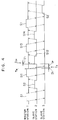
- Fig. 2 illustrates a time chart of codes transmitted and received between the master station 1 and the slave stations 2, 3, ....
- the code transmitted by the master station 1 is illustrated at the upper most part and the codes transmitted by the slave stations 2 and 3 are also illustrated respectively at the intermediate and lower portions.
- the polling signal S1 which is sequentially transmitted from the sending and receiving circuit 18 of the master station 1 to the slave station 2 or 3.
- This polling signal S1 reaches the slave station 2 after a transmission delay time ⁇ 1 and the slave station 3 after a transmission delay time ⁇ 2, through the modem circuit 19 and data transmission path 5, respectively.
- each slave station 2 or 3 status of contacts to be watched such as the auxiliary contacts, for example, of protection relay or circuit breaker, etc. are input to the input circuit 25 or 35, and status change of said contacts may be detected by the CPU 20 or 30 through the periodical scanning for the input circuit 25 or 35. If such status change is detected, such input address number and novel state are stored within the memories (not illustrated) of respective slave stations 2 or 3 with the time data of such status change read by the slave clock 27 or 37. If it is assumed here that said polling signal S1 is destinated, for example, to the slave station 2, CPU 20 returns content of status change stored in said memory not illustrated and detection time of such status change (or such and such if status change is not detected) to the master station 1 as the return code S2.
- This return code S2 is transmitted from the code sending and receiving circuit 28 after a constant time t P from completion of reception of said polling signal S1 and is then transmitted to the master station 1 through the modem circuit 29 and external bus 5A. As illustrated in Fig. 2, the return code S2 from the slave station 2 reaches the code sending and receiving circuit 18 of master station 1 after a transmission delay time ⁇ 1, while the return code S2 from the slave station 3 reaches said circuit 18 after the transmission delay time ⁇ 2.
- CPU 10 Upon reception of the return code S2 from the slave station 2 or 3 through the code sending and receiving circuit 18, CPU 10 updates stored contents of a memory not illustrated within the master station 1. Moreover, CPU 10 renews display on the display panel 11 through the output circuit 14 and then records status changes of the slave station 2 or 3 by operating the typewriter 13 through the typewriter control circuit 16.
- CPU 10 of the master station 1 encodes the address and-the state to be controlled (for example, ON/OFF status of switch) of the facilities in an electrical station, for example, to which a relevant slave station, for example, like the slave station 2 and this slave station are provided, on the basis of an input from the control desk 12 through the input circuit 15 and then outputs this code to the code sending and receiving circuit 18.
- This code sending and receiving circuit 18 receives the information from CPU 10 and sends a selection/control code S3 to the corresponding slave station, for example, the first slave station 2 in place of the polling signal.
- the code sending and receiving circuit 28 or 38 receives this selection/control code S3 and in case the first slave station 2, for example, is selected, the code sending and receiving circuit 28 of such slave station 2 receives such selection/control code S3 and gives a control command to the facilities, for example, of an electrical station to which said first slave station 2 is provided through the output circuit 24.
- the code sending and receiving circuit 28 sends the code as an answer code S4 as in case of the return code S2 based on said status change.
- transmission is carried out, as is obvious from Fig. 2, by the code sending and receiving circuit 28 after a constant time t P from reception of the selection/control code S3 and thereby said code S4 is transmitted to the master station 1 through the modem circuit 29 and external bus 5A.
- the time information sent from the slave station 2 or 3 must be accurate and accordingly, the time setting is carried out periodically (for example, once at twelve o'clock midnight in every day) to the slave clocks 27, 37 of slave stations 2, 3 for time synchronization to the master clock 17.
- CPU 10 of the master station 1 transmits the time setting code S5, encoded time T0 to be set (for example, 24 o'clock 00 minute 00 second 000 millisecond), to each slave station 2, 3, ... through the modem circuit 19 and data transmission path 5 from the code sending and receiving circuit 18 when the preset time comes close.
- the slave stations 2, 3, ... having received such time setting code S5 with the code sending and receiving circuits 28, 38 store the time to be set in the memory of CPUs 20, 30 as the preparation for input of a setting command signal S6.
- CPU 10 of the master station 1 supervises the time of master clock T0 and transmits the setting command signal S6 from the code sending and receiving circuit 18 to the slave stations 2, 3, ... through the modem circuit 19 and external buses 5A, 5B ...
- the setting command signal S6 reaches the slave station 2 after the transmission delay time ⁇ 1 from the preset time T0 and to the slave station 3 after the transmission delay time ⁇ 2.
- CPU 20 of the slave station 2 sets the time of slave clock 27 to T0 + ⁇ 1
- CPU 30 of the slave station 3 sets the time of slave clock 37 to T0 + ⁇ 2.
- the slave stations 2, 3, ... measure the transmission delay times ⁇ 1, ⁇ 2, ... and store such delay times to the memory of CPUs 20, 30, ... and then add to the designated setting time T0 by the time setting code S5.
- CPU Upon completion of processing for time setting, CPU returns again to the remote supervisory control operation by sending the polling signal S1.
- US-A-4 473 889 discloses a method for correlating in a digital data acquisition system the time sequence of a group of events at locations remote from the master station.
- the method corrects the time tags on the events record for the signal transmission time between the master and remote stations and also takes into account the turnaround time at the remote station. In addition, compensation is made for the drift of the remote clocks with reference to the master clock.
- the time synchronization method in the data transmission system to which the present invention pertains discloses that a slave station transmits a code of slave clock time data to the master station in accordance with the code of slave clock time survey command sent from the master station, the master station calculates the time difference between the master clock and the slave clock taking the transmission procedure and the transmission delay time into consideration, such time difference is transmitted to the slave station as the code of time correction data, and the time of slave clock is corrected in the slave station in accordance with time difference received from the master station and thereby the times of master clock and slave clocks are synchronized.
- time correction data is carried out as explained below and the time of slave clock is corrected and synchronized with the master clock on the basis of such time correction data.
- said master station stores in the register the time of master clock when it has received said frame
- calculates an estimated time of slave clock by subtracting the sum of the length of the 1-frame of code, said constant predetermined time and transmission delay time from said stored time, transmits the difference, as the time correction data, between such estimated time and the time of said slave clock input as the data from said slave station
- said slave station receives such data and synchronizes said slave clock to said master clock by adding said difference to the time of said slave clock in order to correct said time.
- a slave station transmits the time of said slave clock, which has been read at predetermined constant time before the partition of frame of code being transmitted to the master station and stored in the register, as the data in said frame following such partition in accordance with the time survey command sent from the master station, while said master station stores the time of said master clock in such a timing of having received said frame to the register and then calculates an estimated time of slave clock which is equal to that obtained by adding a sum of the transmission delay time, the time up to transmission of code from readout of time of said slave clock and length of code 1 frame to the time of said slave clock having been input as the data from said slave station, transmits the difference between said estimated time of slave clock and the time of said master clock at the timing of having received said frame to said slave station as the time correction data, and said slave station receives such time correction data and synchronizes said slave clock to said master clock by adding said difference to the time of said slave clock for correction.
- Fig. 1 is a block diagram illustrating outline of structure of a data transmission system for explaining a time synchronization method of the prior art.
- Fig. 2 is a time chart of bothway data transmission between the master station and slave stations in the data transmission system of Fig. 1.
- Fig. 3 is a block diagram illustrating outline of structure of the data transmission system to which the time synchronization system by the first embodiment of the present invention pertains.
- Fig. 4 is a time chart for explaining operations of the system illustrated in Fig. 3.
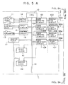
- Fig. 5 is a block diagram illustrating outline of structure of Supervisory Control And Data Acquisition (hereinafter referred to as SCADA) system to which the time synchronization method by the second embodiment of the present invention pertains, and
- SCADA Supervisory Control And Data Acquisition
- Fig. 6 is a pictorial presentation for explaining outline of data to be transmitted or received between the master station and the slave station in the system illustrated in Fig. 5.
- Fig. 3 and Fig. 4 are accompanied for explaining the first embodiment of the present invention and those given the same reference numbers as those in Figs. 1 and 2 indicate the same or corresponding portions in each figure.
- the master station 1 comprises a first register 41 and a second register 42 which are respectively connected with the internal buses 51 and also with the master clock 17 and code sending and receiving circuit 18.
- the first slave station 2 comprises a slave clock register 21 respectively connected with the internal bus 52 and also with the slave clock 27 and code sending and receiving circuit 28
- the second slave station 3 also comprises a slave clock register 31 respectively connected with the internal bus 53 and with the slave clock 37 and code sending and receiving circuit 38.
- many slave stations such as the third, fourth and the succeeding slave stations not illustrated are also connected as in case of Fig. 1.
- Fig. 4 is a time chart which illustrates time relation of code to be transmitted or received in such a time between the master station 1 and the slave stations 2, 3, ....
- the sending code of master station 1 is indicated at the upper most part, while the sending codes of the first and second slave stations 2, 3 at the lower part, respectively.
- the code sending and receiving circuit 18 of the master station 1 transmits the code S11 of the slave clock time survey command to the first slave station 2 and stores the time T M of the master clock 17 in such a timing as completing transmission of code S11 of such slave clock time survey command to the first register 41.
- the code S11 of said slave clock time survey command reaches the first slave station 2 after the transmission delay time ⁇ 1 and when the code S11 of such slave clock time survey command is received, the first slave station 2 stores the time T S of the slave clock 27 in the timing of completing transmission in the slave clock register 21.
- the code S12 of time data of the slave clock which starts transmission after a constant period t P is transmitted with the time data stored in said slave clock register 21.
- the time T De of the master clock 17 in such start timing is stored in the second register 42.
- CPU 10 of the master station 1 calculates the transmission delay time ⁇ 1 between the master station 1 and slave station 2 by the following equation from the time T M and T De stored in said first and second registers 41, 42.
- ⁇ 1 (T De - t P - T M )/2
- a time difference T D 1 between the master clock 17 and slave clock 27 is calculated by the following equation considering such transmission delay time ⁇ 1 and it is transmitted to the slave station 2 as the code S13 of the time correction data.
- T D1 T M + ⁇ 1 - T S
- the time of the slave clock 27 is synchronized with the time of the master clock 17.
- the slave station 2 sends the certification code S14 to the master station 1 in order to certify time synchronization after setting the time of slave clock 27 and the content of such code is certified in the master station 1.
- CPU 10 of the master station 1 transmits the code of time correction data S13 in an adequate timing after detecting the time difference between the master clock 17 and slave clock 27 from the code S11 of the slave clock time survey command and the code S12 of the slave clock time data which is an answer to said code S11.
- a transmission delay time is once calculated and then time difference is obtained based on such delay time, but the same result can also be obtained by the procedures that it is calculated directly by substituting the equation for obtaining the transmission delay time to the equation for obtaining time difference from the times of the first and second registers, time of slave clock register and a constant period up to the transmission start of code of slave clock time data in a slave station.
- transmission delay time can be calculated anytime by each transmission of polling signal and reception of return signal thereto, time difference can be calculated immediately, for example, by storing the data of several times of transmission and reception in the past and abnormal value resulting from disturbance of code due to a noise can be excepted from data.
- This second embodiment relates to the time synchronization of the master clock 17 and slave clocks 27 and 37 between the master station 1 and first and second slave stations 2 and 3 forming Supervisory Control And Data Acquisition (so-called, SCADA) system.
- SCADA Supervisory Control And Data Acquisition
- the internal bus 51 of the master station 1 comprises a code sending circuit 101 for data transmission with the first slave station 2, a modulation circuit 102 provided between such code sending circuit 101 and external line 50A forming the data transmission path 5, a demodulation circuit 103 connected to an external line 50B for returning the data sent from the first slave station 2 and a code receiving circuit 104 provided between such demodulation circuit 103 and the internal bus 51.
- the master station 1 comprises, for data transmission with the second slave station 3, a code sending circuit 105, a modulation circuit 106, a demodulation circuit 107 and a code receiving circuit 108.
- the code receiving circuit 104 which receives data from the second slave station 2 is also connected to the first register 41 and the code receiving circuit 108 which receives data from the second slave station 3 is also connected to the second register 42.
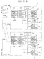
- the first slave station 2 comprises a demodulation circuit 201 connected to said external line 50A, a code receiving circuit 202 provided between such demodulation circuit 201 and internal bus 52, a code sending circuit 203 connected to the internal bus 52 and a modulation circuit 204 provided between the code sending circuit 203 and external line 50B.
- the code sending circuit 203 is connected to the register 21.
- the second slave station 3 comprises a demodulation circuit 301 which demodulates the signal transmitted from the modulation circuit 106 of the master station 1 through the external line 55A, a code receiving circuit 302 provided between such demodulation circuit 301 and internal bus 53, a code sending circuit 303 connected to the internal bus 53 and a modulation circuit 304 provided between the code sending circuit 303 and external line 55B.
- Said code sending circuit 303 is also connected to the register 31 which is connected to the slave clock 37.
- CPU 20 of the first slave station 2 scans conditions of contact to be supervised (such as auxiliary contacts of protection relay or circuit breaker, etc.) input to the input circuit 25 and stores such conditions. If status change occurs in the input contact, the address number of such contact and novel condition are transferred to the code sending circuit 203.
- the code sending circuit 203 always transmits the code to the master station 1.
- the code sending circuit 203 Upon reception of address of said status change contact and data of new status from CPU 20, the code sending circuit 203 transfers such address and data to the modulation circuit 204 in order to send the data to the master station 1 on the code frame next to the code being transmitted at that time.
- An example of code transmitted by the code sending circuit 203 is illustrated as the data 2S of the slave station 2 of Fig. 6. In Fig.
- D is each frame of code and F is a flag indicating partition between the frames D .
- a pattern of flag F is fixed but the frame D changes including the length thereof in accordance with the content to be transmitted.
- a control part for certain transmission and reception and a code check part are generally added in addition to the data to be transmitted.
- the code format there is the high-level data link control (hereinafter referred to as HDLC) procedure.
- the modulation circuit 204 modulates the code received from the code sending circuit 203 into the signal, for example the frequency shift keying (hereinafter referred to as FSK) signal which is suited to the signal transmission line and is resistive to influence of noise and then transmits it to the master station 1 through the external bus 50B which forms the signal transmission line.
- FSK frequency shift keying
- the demodulation circuit 103 receives such signal, demodulates the signal into a DC pulse and then transfers the pulse to the code receiving circuit 104.
- the code having reached the code receiving circuit 104 is delayed as long as the transmission delay time t P as in case of the sending code 2S like the receiving data 2R of the master station 1 illustrated in Fig. 6.
- CPU 10 of the master station 1 reads the received content from the periodical scanning or the interrupt signal from the code receiving circuit 104.
- CPU 10 updates contents of own memory and changes display on the display panel 11 through the output circuit 14.
- such status change is recorded by the typewriter 13 through the typewriter control circuit 16.
- CPU 10 of the master station 1 also scans the input from the control desk 12 through the input circuit 15 and encodes the device address and status to be controlled (ON-OFF status), if selection, control command is issued for said device of the slave station 2 and applies such codes to the code sending circuit 101.
- the code sending circuit 101 is transmitting the code indicated as the sending data 2S of Fig. 6 and transmits such code on the one frame of such sending data code to the code receiving circuit 202 of the first slave station 2 through the modulation circuit 102, external bus 50A of transmission line 5 and demodulation circuit 201.
- CPU 20 of the first slave station 2 reads the receiving content by the periodical scanning or interrupt signal as a receiving data 1R sent from the code receiving circuit 202 and gives control command to the designated device through the output circuit after code check and decoding.
- the slave clocks 27, 37, ... are provided respectively to the slave stations 2, 3, ... and these slave clocks are synchronized with the master clock 17.
- times of slave clocks 27, 37, ... are also transmitted to the master station 1. Namely, if status change occurs at the contact being inputted to the input circuit 25 of the first slave station 2 explained previously, CPU 20 transmits the time of slave clock 27 to the master station 1 together with the address number of relevant contact and new status.
- CPU 10 of the master station 1 once stores such data to the memory of CPU 10 and arranges in order these data in the sequence of time added after acquisition of the data from the other slave station during a constant period and then outputs such data by the typewriter 13 through the typewriter control circuit 16. Thereby, an operator knows the correct operation time and its sequence.
- the master clock 17 of the master station 1 and the slave clocks 27, 37, ... of the slave stations 2, 3, ... must be synchronized with considerable accuracy (for example, within several milliseconds) and operations for such synchronization will then be explained hereunder.
- CPU 10 of the master station 1 issues a time survey command for checking the times of slave clocks 27, 37 ... once in every constant period (once in every hour to every day in accordance with accuracy of slave clock) to the slave stations 2, 3, ... through the code sending circuits 101, 105, ....
- the code sending circuit 203 sends a signal to the register 21 before a constant time t a determined previously of the code frame transmission starting time and the register 21 repeatedly reads and stores the time of slave clock 27 in such a timing as such signal is inputted.
- the code sending circuit 101 transmits it to the code receiving circuit 202 of the slave station 2 through the modulation circuit 102, external bus 50A forming the transmission line 5 and demodulation circuit 201.
- D TIQ
- TIQ time survey command D
- CPU 20 of the slave station 2 puts the data stored in the register 21 on the next code frame.
- the data of register 21 is the time of slave clock 27, as indicated at the upper part of the sending data 2S of Fig. 6, before the time t a from the next frame (at the end of transmission of the previous frame in this example), if it is considered as T S1 , the CPU 20 transmits this T S1 as the time data of slave clock 27 in the next frame D (TAS) to the code receiving circuit 104 through the code sending circuit 203, modulation circuit 204, external bus 50B and demodulation circuit 103.
- T S1 time data of slave clock 27 in the next frame D
- the signal input to the code receiving circuit 103 is delayed as long as the transmission delay time ⁇ like the sending data 2S as in the case of receiving data 1R of Fig. 6.
- the code receiving circuit 104 Upon reception of frame containing the time data of slave clock 27, the code receiving circuit 104 reads the time T M of master clock 17 at this time and then stores it in the register 41.
- CPU 10 reads said time data T M stored in said register 41, calculates an estimated time T S10 of the slave clock by subtracting a sum of the length t c of the 1-frame of code previously known, time t a up to the transmission of code from read of time of slave clock described previously and a transmission delay time ⁇ from said time data T M and obtains a difference (T S10 - T S1 ) between such estimated time and the time T S1 of slave clock input with the frame of D (TAS) from the slave station and then stores it in the own memory as the time difference between the master clock 0 and slave clock 1.
- CPU 10 of the master station 1 transmits said time difference as the slave clock correction data to the code receiving circuit 202 of the first slave station 2 through the code sending circuit 101, modulation circuit 102, external bus 50A and demodulation circuit 201.
- the time chart of this operation is indicated by the frame D (TAJ) of Fig. 6.
- CPU 20 of the first slave station 2 reads the time of slave clock 27, adds the time correction data (including the sign) thereto and set the time of slave clock 27 to such time data.
- TJ time correction data D
- slave clock 27 is synchronized with the time of master clock 17.
- Time synchronization can be performed with the same operations for the slave clock 37 of second slave station 3 and the succeeding ones.
- the time correction data can also be obtained as a difference (T I - T M ) between the estimated time T I of slave clock attained by CPU 10 of the master station 1 by adding a sum of the transmission delay time ⁇ , time t a up to transmission of code from reading of time of slave clock and the length t c of the 1-frame of code to the time T S1 of slave clock 27 input, on the contrary from the above case, for example, from the first slave station 2.
- the time synchronization method of the present invention can be applied to the data transmission system which always transmits the code and such system is also explained in the embodiments, but it is certain that this method of the present invention can also be adopted to the other system, for example, those which do not always transmit the codes and each slave station transmits the codes in accordance with the polling from the master station.
- the time correcting operations of slave clocks of slave stations may be done in parallel, for example, by providing individually the register 41, 42, ... of the master station 1 as in case of the embodiment, but it is also certainly possible that various structures may be employed, for example, the one common register may be used sequentially by realizing sequential correction for slave station by slave station.
- the transmission delay time ⁇ between the master station and slave stations is measured, when the data transmission system is installed, by the loop-back test, wherein, for example, the modulation circuit 102 and demodulation circuit 103 of the master station and the modulation circuit 204 and demodulation circuit 201 of the first slave station 2 are separated from the internal circuits in Fig. 5, an output of the demodulation circuit 201 is connected to the modulation circuit 204 and the time until appearance of change in the input code of the modulation circuit 102 of the master station 1 in the output of demodulation circuit 103 is measured and then is divided by 2, and then it is stored as the data in the memory of CPU 10 of the master station 1.
- the time correcting operations are not always required to be executed for all digits (hour, minute, second, millisecond) of time in every operation and it is also possible that correction up to the digit of second (or time setting of slave clock by transmitting the absolute time) is carried out at the time of starting operation of device or with a period of long time and the slave clock time and bit length of its corrected data may be subtracted by once correcting millisecond every hour.
- the slave station returns time data of the slave clock to the master station in accordance with the slave clock time survey command to the slave station from the master station in the data transmission system, while the master station calculates transmission delay time based on the time when the code including such time data has arrived from the slave station, obtains a time difference between the master clock and slave station by adding such transmission delay time as an element for calculation and synchronizes the times of the master station and slave station of data transmission system by correcting the time of the slave clock on the basis of such time difference data.
- the time synchronization method of the present invention is capable of executing the time correcting operation with reference to the absolute time and provides following effects for the practical use. First, it is no longer necessary to interrupt the other operations to be carried out by CPU provided in the master station and slave stations for the time synchronization and thereby an excessive load to be applied on CPU can be prevented.
- the times of clocks provided in the master station and slave stations may be synchronized without suspending flow of data transmission, and alleviation of load applied on CPU and improvement of transmission efficiency can also be improved from such point of view.
Landscapes
- Engineering & Computer Science (AREA)
- Computer Networks & Wireless Communication (AREA)
- Signal Processing (AREA)
- Power Engineering (AREA)
- Selective Calling Equipment (AREA)
- Synchronisation In Digital Transmission Systems (AREA)
Claims (4)
- Procédé de synchronisation temporelle dans lequel une station maître (1) équipée d'au moins une unité centrale de traitement (10) (CPU), d'une horloge maître (17) et de moyens de transmission/réception (18) est connectée à une station esclave et/ou des stations (2; 3) ayant au moins une unité CPU (20; 30), une horloge esclave (27; 37) et des moyens de transmission/réception (28; 38), à travers la ligne de transmission de données (5), et dans lequel le temps de ladite horloge esclave et/ou d'horloges (27; 37) dans le système de transmission de données qui assurent une transmission de données bidirectionnelle entre ladite station maître (1) et la station esclave et/ou les stations (2; 3) est synchronisé avec le temps de ladite horloge maître (17), ledit procédé de synchronisation temporelle comprenant:
une première étape dans laquelle ladite station maître (1) transmet le code d'une commande de relevé de temps d'horloge esclave à ladite station esclave (2; 3) et le temps TM de ladite station maître (1) à la position temporelle de la fin de la transmission de ce code est mémorisé dans un premier registre (41) prévu dans ladite station maître (1) au moment de cette transmission;
une seconde étape dans laquelle une station esclave (2; 3) qui a reçu le code de ladite commande de relevé de temps d'horloge esclave mémorise le temps TS de ladite horloge esclave (27; 37) à la position temporelle de la fin de la réception dudit code reçu en provenance de ladite station maître (1) dans un registre de station esclave (21; 31) prévu dans ladite station esclave, et transmet ensuite le temps Ts de ladite horloge esclave, mémorisé dans ledit registre (21; 31), à ladite station maître (1), au moment de la transmission, par la suite, le code de données de temps d'horloge esclave étant prédéfini de façon à ce que la transmission de ladite station maître (1) soit démarrée après une période constante tp à partir de la position temporelle de la fin de la réception dudit code;
caractérisé par
une troisième étape dans laquelle ladite station maître (1) qui a reçu le code desdites données d'horloge esclave lit le temps TDe de ladite horloge maître à la position temporelle du départ de la réception dudit code et le mémorise dans un second registre (42), et par la suite, obtient, sur la base de deux données temporelles de l'horloge esclave, un temps TS à la position temporelle de la fin de la réception dudit code de commande de relevé de temps dans l'horloge esclave (27; 37) transmise dans le code de ces données de temps d'horloge esclave et le temps d'horloge maître TM à la position temporelle de la fin de la transmission dudit code de commande de relevé de temps mémorisé dans ledit premier registre (41), une différence de temps TD1 entre ladite horloge maître (17) et ladite horloge esclave (27; 37) prenant en compte les temps respectifs mémorisés dans lesdits premier et second registres (41; 42) et le temps de retard de transmission τ₁ calculé à partir d'un temps constant jusqu'au départ de la transmission du code desdites données de temps d'horloge d'esclave dans ladite station esclave (2; 3) τ₁ = (TDe - tp - TM)/2, et transmet cette différence de temps TD1 = TM + τ₁ - TS à ladite station esclave (2; 3) dans le code des données de correction temporelle; et
une quatrième étape dans laquelle ladite station esclave (2; 3) qui a reçu ladite différence de temps TD1 dans ledit code des données de correction temporelle corrige le temps de ladite horloge esclave (27; 37) en fonction de cette différence de temps. - Procédé de ,synchronisation temporelle du système de transmission de données selon la revendication 1, dans lequel ledit temps de retard de transmission pris en compte pour obtenir une différence de temps entre ladite horloge maître (17) et ladite horloge esclave (27; 37) dans ladite troisième étape est calculé par ladite unité CPU (20; 30) en fonction des données fournies plusieurs fois dans le passé à ladite station maître (1).
- Procédé de synchronisation temporelle dans lequel une station maître (1) équipée d'au moins une unité centrale de traitement (10) (CPU), d'une horloge maître (17) et de moyens de transmission/réception (18) est connectée à une station esclave et/ou des stations (2; 3) ayant au moins une unité CPU (20; 30); une horloge esclave (27; 37) et des moyens de transmission/réception (28; 38), à travers la ligne de transmission de données (5), et dans lequel le temps de ladite horloge esclave et/ou d'horloges (27; 37) dans le système de transmission de données qui assurent une transmission de données bidirectionnelle entre ladite station maître (1) et la station esclave et/ou les stations (2; 3) est synchronisé avec le temps de ladite horloge maître (17), ledit procédé de synchronisation temporelle comprenant:
une première étape pour transmettre le temps TS1 de l'horloge esclave (27; 37) qui est lu à un temps constant ta avant la partition de la trame du code en cours de transmission de ladite station esclave (2; 3) à ladite station maître (1) en accord avec la commande de relevé de temps d'horloge esclave transmise par ladite station maître (1), et est mémorisé dans un registre de station esclave (21; 31) comme étant les données à transmettre à la trame suivant ladite partition;
caractérisé par
une seconde étape pour calculer un temps d'horloge esclave estimé TS10 en soustrayant une somme de la longueur tc d'une trame du code transmis, dudit temps constant ta et du temps de retard de transmission τ audit temps TM de l'horloge maître (17) à la position temporelle de la fin de réception de ladite trame après que ce temps TM ait été mémorisé dans le premier registre (41) de la station maître, et ensuite, pour transmettre une différence de temps (TS10 - TS1) entre ce temps TS10 et le temps TS1 de ladite horloge esclave à ladite station esclave (2; 3) comme étant les données de correction temporelle; et
une troisième étape pour corriger le temps en ajoutant ladite différence de temps reçue par ladite station esclave (2; 3) au temps réel de l'horloge esclave (27; 37). - Procédé de synchronisation temporelle selon la revendication 3, caractérisé en ce que ladite seconde étape est remplacée par l'étape consistant à calculer un temps d'horloge esclave estimé TI obtenu en ajoutant une somme du temps de retard de transmission τ, d'un temps ta jusqu'à la transmission du code à partir de la lecture du temps de ladite horloge esclave (27; 37) et de la longueur tc de la trame 1 de code au temps TS1 de ladite horloge esclave fournie en entrée comme étant les données provenant de ladite station esclave (2; 3) après que ladite station maître (1) ait mémorisé le temps TM de l'horloge maître à la position temporelle de la fin de la réception de ladite trame dans le premier registre (41) de ladite station maître (1), et ensuite, à transmettre une différence de temps (TM - TI), entre ce temps d'horloge esclave estimé TI et le temps TM de ladite horloge maître (17) à la position temporelle de la fin de la réception de la trame, à ladite station esclave (2; 3) comme étant les données de correction temporelle.
Applications Claiming Priority (4)
| Application Number | Priority Date | Filing Date | Title |
|---|---|---|---|
| JP115662/86 | 1986-05-20 | ||
| JP11566286A JPH065309B2 (ja) | 1986-05-20 | 1986-05-20 | 時刻同期方法 |
| JP61142780A JPH0618364B2 (ja) | 1986-06-20 | 1986-06-20 | デ−タ伝送システムの時刻同期方法 |
| JP142780/86 | 1986-06-20 |
Publications (3)
| Publication Number | Publication Date |
|---|---|
| EP0253096A2 EP0253096A2 (fr) | 1988-01-20 |
| EP0253096A3 EP0253096A3 (en) | 1990-05-02 |
| EP0253096B1 true EP0253096B1 (fr) | 1995-10-25 |
Family
ID=26454139
Family Applications (1)
| Application Number | Title | Priority Date | Filing Date |
|---|---|---|---|
| EP87107110A Expired - Lifetime EP0253096B1 (fr) | 1986-05-20 | 1987-05-16 | Procédé de synchronisation des horloges dans un système de transmission de données |
Country Status (3)
| Country | Link |
|---|---|
| US (1) | US4807259A (fr) |
| EP (1) | EP0253096B1 (fr) |
| DE (1) | DE3751571T2 (fr) |
Cited By (1)
| Publication number | Priority date | Publication date | Assignee | Title |
|---|---|---|---|---|
| CN110572234A (zh) * | 2019-10-22 | 2019-12-13 | 深圳震有科技股份有限公司 | 一种基于串口实现时钟同步的方法、智能终端及存储介质 |
Families Citing this family (61)
| Publication number | Priority date | Publication date | Assignee | Title |
|---|---|---|---|---|
| FR2616024B1 (fr) * | 1987-05-26 | 1989-07-21 | Quinquis Jean Paul | Systeme et methode de controle de flux de paquets |
| CH670545GA3 (fr) * | 1987-10-28 | 1989-06-30 | ||
| US4893318A (en) * | 1988-01-26 | 1990-01-09 | Computer Sports Medicine, Inc. | Method for referencing multiple data processors to a common time reference |
| JPH0226141A (ja) * | 1988-07-15 | 1990-01-29 | Nec Corp | 無線回線制御方式 |
| US4937819A (en) * | 1988-09-26 | 1990-06-26 | A.T. & T. Paradyne | Time orthogonal multiple virtual dce for use in analog and digital networks |
| GB8903567D0 (en) * | 1989-02-16 | 1989-04-05 | British Telecomm | An optical network |
| US5105439A (en) * | 1989-08-11 | 1992-04-14 | Motorola, Inc. | Delay equalization detector |
| US5036528A (en) * | 1990-01-29 | 1991-07-30 | Tandem Computers Incorporated | Self-calibrating clock synchronization system |
| DE4105267A1 (de) * | 1990-02-27 | 1991-08-29 | Motorola Inc | Verbesserte synchronisationstechnik |
| US5042053A (en) * | 1990-08-16 | 1991-08-20 | Honeywell Inc. | Zero-sync-time apparatus for encoding and decoding |
| US5206857A (en) * | 1991-04-29 | 1993-04-27 | At&T Bell Laboratories | Apparatus and method for timing distribution over an asynchronous ring |
| US5455935A (en) * | 1991-05-31 | 1995-10-03 | Tandem Computers Incorporated | Clock synchronization system |
| US5327468A (en) * | 1992-06-19 | 1994-07-05 | Westinghouse Electric Corp. | Synchronization of time-of-day clocks in a distributed processing network system |
| NO176860C (no) * | 1992-06-30 | 1995-06-07 | Geco As | Fremgangsmåte til synkronisering av systemer for seismiske undersökelser, samt anvendelser av fremgangsmåten |
| GB2271251B (en) * | 1992-10-01 | 1996-08-14 | Digital Equipment Int | Timer synchronisation system |
| JP3057934B2 (ja) * | 1992-10-30 | 2000-07-04 | 日本電気株式会社 | 共有バス調停機構 |
| US5870427A (en) * | 1993-04-14 | 1999-02-09 | Qualcomm Incorporated | Method for multi-mode handoff using preliminary time alignment of a mobile station operating in analog mode |
| US5509035A (en) * | 1993-04-14 | 1996-04-16 | Qualcomm Incorporated | Mobile station operating in an analog mode and for subsequent handoff to another system |
| KR960009539B1 (en) * | 1993-12-27 | 1996-07-20 | Hyundai Electronics Ind | Apparatus for synchronizing time using satellite |
| US6334219B1 (en) * | 1994-09-26 | 2001-12-25 | Adc Telecommunications Inc. | Channel selection for a hybrid fiber coax network |
| GB2296166B (en) * | 1994-11-29 | 1999-07-07 | Plessey Telecomm | Clock synchronisation |
| US7280564B1 (en) | 1995-02-06 | 2007-10-09 | Adc Telecommunications, Inc. | Synchronization techniques in multipoint-to-point communication using orthgonal frequency division multiplexing |
| USRE42236E1 (en) | 1995-02-06 | 2011-03-22 | Adc Telecommunications, Inc. | Multiuse subcarriers in multipoint-to-point communication using orthogonal frequency division multiplexing |
| US5751220A (en) * | 1995-07-14 | 1998-05-12 | Sensormatic Electronics Corporation | Synchronized network of electronic devices including back-up master units |
| JPH0964874A (ja) * | 1995-08-28 | 1997-03-07 | Sony Corp | データ伝送方法およびデータ伝送システム |
| US6027195A (en) * | 1996-11-12 | 2000-02-22 | Varis Corporation | System and method for synchronizing the piezoelectric clock sources of a plurality of ink jet printheads |
| WO1999005820A2 (fr) * | 1997-07-24 | 1999-02-04 | Innomedia Pte Ltd. | Systeme et procede de communication sans fil |
| JP3424901B2 (ja) | 1997-12-05 | 2003-07-07 | 株式会社日立製作所 | 多重系制御装置の同期方式および同期方法 |
| US6373834B1 (en) * | 1997-12-19 | 2002-04-16 | Telefonaktiebolaget Lm Ericsson | Synchronization for cellular telecommunications network |
| US6128318A (en) * | 1998-01-23 | 2000-10-03 | Philips Electronics North America Corporation | Method for synchronizing a cycle master node to a cycle slave node using synchronization information from an external network or sub-network which is supplied to the cycle slave node |
| SG81231A1 (en) * | 1998-05-25 | 2001-06-19 | Nanyang Polytechnic | Wireless synchronous clock system |
| US6279058B1 (en) * | 1998-07-02 | 2001-08-21 | Advanced Micro Devices, Inc. | Master isochronous clock structure having a clock controller coupling to a CPU and two data buses |
| US6236623B1 (en) * | 1998-10-16 | 2001-05-22 | Moore Industries | System and method for synchronizing clocks in a plurality of devices across a communication channel |
| AU758059B2 (en) * | 1999-05-04 | 2003-03-13 | Two Way Media Limited | Interactive applications |
| US6611538B1 (en) | 1999-05-27 | 2003-08-26 | 3Com Corporation | Data transmission synchronization system |
| US6646953B1 (en) | 2000-07-06 | 2003-11-11 | Rambus Inc. | Single-clock, strobeless signaling system |
| US6643787B1 (en) | 1999-10-19 | 2003-11-04 | Rambus Inc. | Bus system optimization |
| US6502141B1 (en) * | 1999-12-14 | 2002-12-31 | International Business Machines Corporation | Method and system for approximate, monotonic time synchronization for a multiple node NUMA system |
| US6614862B1 (en) * | 1999-12-30 | 2003-09-02 | Sun Microsystems, Inc. | Encoded clocks to distribute multiple clock signals to multiple devices in a computer system |
| US7068746B1 (en) * | 2000-03-01 | 2006-06-27 | Lucent Technologies Inc. | Base station transceiver to radio network controller synchronization filtering function |
| GB2359960B (en) * | 2000-03-03 | 2004-06-16 | Mitel Corp | Embedded loop delay compensation circuit for multi-channel transceiver |
| JP2002049605A (ja) * | 2000-08-02 | 2002-02-15 | Fujitsu Ltd | タイマ調整システム |
| US6577872B1 (en) | 2000-08-08 | 2003-06-10 | Telefonaktiebolaget Lm Ericsson (Publ) | Base station oscillator regulation independent of transport network clocks in cellular telecommunications network |
| JP3674533B2 (ja) * | 2001-04-24 | 2005-07-20 | 日本電気株式会社 | 波長多重システムにおけるosc信号のクロック同期監視方法 |
| US7818457B1 (en) * | 2001-05-22 | 2010-10-19 | Rockwell Automation Technologies, Inc. | Apparatus for multi-chassis configurable time synchronization |
| US7007106B1 (en) * | 2001-05-22 | 2006-02-28 | Rockwell Automation Technologies, Inc. | Protocol and method for multi-chassis configurable time synchronization |
| US7080274B2 (en) * | 2001-08-23 | 2006-07-18 | Xerox Corporation | System architecture and method for synchronization of real-time clocks in a document processing system |
| US7337344B2 (en) * | 2003-01-31 | 2008-02-26 | Point Grey Research Inc. | Methods and apparatus for synchronizing devices on different serial data buses |
| JP2004266477A (ja) * | 2003-02-28 | 2004-09-24 | Orion Denki Kk | 映像受信装置 |
| CN101297332B (zh) * | 2005-09-09 | 2010-05-12 | 传感电子公司 | 提供同步发送的电子物品监视系统 |
| JP2009512281A (ja) * | 2005-10-06 | 2009-03-19 | アビオム、インク. | パケットベースのシステムにおけるジッター管理および待ち時間補正のための方法およびシステム |
| EP2031804A1 (fr) * | 2006-06-22 | 2009-03-04 | Sanritz Automation Co., Ltd. | Dispositif e/s, syteme de reseau avec un dispositif e/s et procede de communication dans un systeme de reseau avec un dispositif e/s |
| US7680154B2 (en) * | 2007-12-31 | 2010-03-16 | Intel Corporation | Methods and apparatus for synchronizing networked audio devices |
| JP5336611B2 (ja) * | 2009-02-24 | 2013-11-06 | テレフオンアクチーボラゲット エル エム エリクソン(パブル) | 通信ネットワークにおけるクロック回復 |
| CN102035639B (zh) | 2009-09-30 | 2014-09-17 | 华为技术有限公司 | 时间同步方法、装置和系统 |
| JP2012186746A (ja) * | 2011-03-08 | 2012-09-27 | Sony Corp | 映像送信装置、映像送信装置の制御方法、映像受信装置および映像受信装置の制御方法 |
| FR2979506B1 (fr) * | 2011-08-30 | 2013-08-30 | Bull Sas | Procede de synchronisation d'une grappe de serveurs et grappe de serveurs mettant en oeuvre ce procede |
| BR112015030705B1 (pt) * | 2013-07-10 | 2022-05-10 | Tlv Co., Ltd | Sistema de sincronização de tempo e método para definir o tempo usando um dispositivo de controle |
| CN104202137A (zh) * | 2014-07-09 | 2014-12-10 | 北京东土科技股份有限公司 | 一种基于e1链路的ieee1588时钟同步方法、系统及装置 |
| WO2018068180A1 (fr) * | 2016-10-10 | 2018-04-19 | 海能达通信股份有限公司 | Nœud maître, nœud esclave, et procédé d'autocorrection d'informations de synchronisation |
| CN109981418B (zh) * | 2019-04-11 | 2020-08-04 | 广东电网有限责任公司 | 一种通信质量感知系统 |
Family Cites Families (9)
| Publication number | Priority date | Publication date | Assignee | Title |
|---|---|---|---|---|
| US3872437A (en) * | 1972-12-12 | 1975-03-18 | Robertshaw Controls Co | Supervisory control system |
| US3940558A (en) * | 1975-01-31 | 1976-02-24 | Digital Communications Corporation | Remote master/slave station clock |
| US4142069A (en) * | 1977-06-20 | 1979-02-27 | The United States Of America As Represented By The Secretary Of The Army | Time reference distribution technique |
| US4368987A (en) * | 1980-06-25 | 1983-01-18 | The United States Of America As Represented By The Secretary Of The Navy | Conjugate-phase, remote-clock synchronizer |
| US4377859A (en) * | 1980-09-02 | 1983-03-22 | International Telephone And Telegraph Corporation | Time slot interchanger and control processor apparatus for use in a telephone switching network |
| US4357701A (en) * | 1980-09-12 | 1982-11-02 | Bell Telephone Laboratories, Incorporated | Digital concentrator terminal synchronization |
| JPS5769496A (en) * | 1980-10-16 | 1982-04-28 | Mitsubishi Electric Corp | Remote controller |
| US4473889A (en) * | 1981-09-11 | 1984-09-25 | Leeds & Northrup Company | Remote correlation of sequence of events |
| JPH0668799B2 (ja) * | 1987-03-02 | 1994-08-31 | 三菱電機株式会社 | 遠方監視制御方式 |
-
1987
- 1987-05-16 EP EP87107110A patent/EP0253096B1/fr not_active Expired - Lifetime
- 1987-05-16 DE DE3751571T patent/DE3751571T2/de not_active Expired - Fee Related
- 1987-05-18 US US07/050,576 patent/US4807259A/en not_active Expired - Lifetime
Cited By (1)
| Publication number | Priority date | Publication date | Assignee | Title |
|---|---|---|---|---|
| CN110572234A (zh) * | 2019-10-22 | 2019-12-13 | 深圳震有科技股份有限公司 | 一种基于串口实现时钟同步的方法、智能终端及存储介质 |
Also Published As
| Publication number | Publication date |
|---|---|
| DE3751571D1 (de) | 1995-11-30 |
| DE3751571T2 (de) | 1996-04-11 |
| EP0253096A3 (en) | 1990-05-02 |
| US4807259A (en) | 1989-02-21 |
| EP0253096A2 (fr) | 1988-01-20 |
Similar Documents
| Publication | Publication Date | Title |
|---|---|---|
| EP0253096B1 (fr) | Procédé de synchronisation des horloges dans un système de transmission de données | |
| US4860001A (en) | Remote monitoring and controlling system | |
| US4894846A (en) | Method for maintaining a correct time in a distributed processing system | |
| US5519726A (en) | Industrial controller with coordinated timing | |
| US4473889A (en) | Remote correlation of sequence of events | |
| EP0613271A2 (fr) | Méthode et dispositif pour synchronisation temparelle des LANs, y compris des réseaux hiérarchiques | |
| EP0078517B1 (fr) | Système de relais de protection et méthode de synchronisation d'échantillonnage | |
| GB2300789A (en) | Transmission time measurement in data networks | |
| US4633421A (en) | Method for transposing time measurements from one time frame to another | |
| US4545029A (en) | Remote correlation of sequence of events | |
| WO1989009443A1 (fr) | Systeme de communication de donnees | |
| JPH0618364B2 (ja) | デ−タ伝送システムの時刻同期方法 | |
| EP0965197A1 (fr) | Consignation et analyse des evenements dans des reseaux de telecommunications | |
| JPH0697975A (ja) | データ通信システム | |
| JPH065309B2 (ja) | 時刻同期方法 | |
| JPH0310278B2 (fr) | ||
| JP2821091B2 (ja) | 遠方監視制御装置および時刻同期装置 | |
| AU716041B2 (en) | Event recording and analysis in telecommunications networks | |
| JPH11231077A (ja) | 時計情報制御方式 | |
| JPH0657003B2 (ja) | 分散形プロセス制御システム | |
| JP3218690B2 (ja) | データ伝送システムの時刻同期方法 | |
| JPS6380662A (ja) | 自動通報装置 | |
| JP3344176B2 (ja) | 同期信号出力方式 | |
| JP2837523B2 (ja) | 端末用網制御装置 | |
| JPH0450798B2 (fr) |
Legal Events
| Date | Code | Title | Description |
|---|---|---|---|
| PUAI | Public reference made under article 153(3) epc to a published international application that has entered the european phase |
Free format text: ORIGINAL CODE: 0009012 |
|
| AK | Designated contracting states |
Kind code of ref document: A2 Designated state(s): CH DE GB LI |
|
| PUAL | Search report despatched |
Free format text: ORIGINAL CODE: 0009013 |
|
| AK | Designated contracting states |
Kind code of ref document: A3 Designated state(s): CH DE GB LI |
|
| 17P | Request for examination filed |
Effective date: 19900504 |
|
| 17Q | First examination report despatched |
Effective date: 19921229 |
|
| GRAA | (expected) grant |
Free format text: ORIGINAL CODE: 0009210 |
|
| AK | Designated contracting states |
Kind code of ref document: B1 Designated state(s): CH DE GB LI |
|
| REF | Corresponds to: |
Ref document number: 3751571 Country of ref document: DE Date of ref document: 19951130 |
|
| REG | Reference to a national code |
Ref country code: CH Ref legal event code: NV Representative=s name: WILLIAM BLANC & CIE CONSEILS EN PROPRIETE INDUSTRI |
|
| PLBE | No opposition filed within time limit |
Free format text: ORIGINAL CODE: 0009261 |
|
| STAA | Information on the status of an ep patent application or granted ep patent |
Free format text: STATUS: NO OPPOSITION FILED WITHIN TIME LIMIT |
|
| 26N | No opposition filed | ||
| PGFP | Annual fee paid to national office [announced via postgrant information from national office to epo] |
Ref country code: DE Payment date: 20010508 Year of fee payment: 15 |
|
| PGFP | Annual fee paid to national office [announced via postgrant information from national office to epo] |
Ref country code: CH Payment date: 20010511 Year of fee payment: 15 |
|
| PGFP | Annual fee paid to national office [announced via postgrant information from national office to epo] |
Ref country code: GB Payment date: 20010516 Year of fee payment: 15 |
|
| REG | Reference to a national code |
Ref country code: GB Ref legal event code: IF02 |
|
| PG25 | Lapsed in a contracting state [announced via postgrant information from national office to epo] |
Ref country code: GB Free format text: LAPSE BECAUSE OF NON-PAYMENT OF DUE FEES Effective date: 20020516 |
|
| PG25 | Lapsed in a contracting state [announced via postgrant information from national office to epo] |
Ref country code: LI Free format text: LAPSE BECAUSE OF NON-PAYMENT OF DUE FEES Effective date: 20020531 Ref country code: CH Free format text: LAPSE BECAUSE OF NON-PAYMENT OF DUE FEES Effective date: 20020531 |
|
| PG25 | Lapsed in a contracting state [announced via postgrant information from national office to epo] |
Ref country code: DE Free format text: LAPSE BECAUSE OF NON-PAYMENT OF DUE FEES Effective date: 20021203 |
|
| GBPC | Gb: european patent ceased through non-payment of renewal fee |
Effective date: 20020516 |
|
| REG | Reference to a national code |
Ref country code: CH Ref legal event code: PL |