EP0253220A2 - Tuyau flexible ayant des cannelures annulaires parallèles et un support axial - Google Patents
Tuyau flexible ayant des cannelures annulaires parallèles et un support axial Download PDFInfo
- Publication number
- EP0253220A2 EP0253220A2 EP87109537A EP87109537A EP0253220A2 EP 0253220 A2 EP0253220 A2 EP 0253220A2 EP 87109537 A EP87109537 A EP 87109537A EP 87109537 A EP87109537 A EP 87109537A EP 0253220 A2 EP0253220 A2 EP 0253220A2
- Authority
- EP
- European Patent Office
- Prior art keywords
- hose
- spacers
- ring
- contact
- adjacent
- Prior art date
- Legal status (The legal status is an assumption and is not a legal conclusion. Google has not performed a legal analysis and makes no representation as to the accuracy of the status listed.)
- Granted
Links
- 125000006850 spacer group Chemical group 0.000 claims abstract description 78
- 238000013016 damping Methods 0.000 claims abstract description 31
- 238000005452 bending Methods 0.000 claims abstract description 20
- 230000007935 neutral effect Effects 0.000 claims abstract description 12
- 239000000463 material Substances 0.000 claims description 13
- 210000002105 tongue Anatomy 0.000 claims description 7
- 239000002657 fibrous material Substances 0.000 claims description 2
- 239000002184 metal Substances 0.000 description 6
- 238000010276 construction Methods 0.000 description 5
- 230000000694 effects Effects 0.000 description 5
- 230000005540 biological transmission Effects 0.000 description 2
- 230000015572 biosynthetic process Effects 0.000 description 2
- 230000006735 deficit Effects 0.000 description 2
- 239000004744 fabric Substances 0.000 description 2
- 239000000835 fiber Substances 0.000 description 2
- 238000010521 absorption reaction Methods 0.000 description 1
- 230000006978 adaptation Effects 0.000 description 1
- 230000002411 adverse Effects 0.000 description 1
- 230000004323 axial length Effects 0.000 description 1
- 230000006835 compression Effects 0.000 description 1
- 238000007906 compression Methods 0.000 description 1
- 238000011109 contamination Methods 0.000 description 1
Images


Classifications
-
- F—MECHANICAL ENGINEERING; LIGHTING; HEATING; WEAPONS; BLASTING
- F16—ENGINEERING ELEMENTS AND UNITS; GENERAL MEASURES FOR PRODUCING AND MAINTAINING EFFECTIVE FUNCTIONING OF MACHINES OR INSTALLATIONS; THERMAL INSULATION IN GENERAL
- F16L—PIPES; JOINTS OR FITTINGS FOR PIPES; SUPPORTS FOR PIPES, CABLES OR PROTECTIVE TUBING; MEANS FOR THERMAL INSULATION IN GENERAL
- F16L11/00—Hoses, i.e. flexible pipes
- F16L11/04—Hoses, i.e. flexible pipes made of rubber or flexible plastics
- F16L11/11—Hoses, i.e. flexible pipes made of rubber or flexible plastics with corrugated wall
- F16L11/115—Hoses, i.e. flexible pipes made of rubber or flexible plastics with corrugated wall having reinforcements not embedded in the wall
Definitions
- the invention relates to a bendable hose with mutually parallel, annular shafts, terminal connection parts and longitudinal support means holding them against axial change in distance and firmly connected to the connection parts in the pulling and / or pushing direction in the form of at least one flexible cable which extends essentially parallel to the hose.
- the relative position between the hose and the rope being given by spacers which are arranged at intervals and distributed over the length of the hose and the hose being guided and supported in the radial direction by the rope.
- the generic hoses which are also called bellows, are usually made of metal. Depending on the application, however, other materials, in particular plastic, can also be used.
- the hoses are usually used for the flexible connection of two media-carrying parts to which they are connected. As is known, if the medium has an overpressure, the hose tries to increase its length, so that it is necessary to keep the axial length spacing of the hose connection parts by additional means, which are essentially formed here by one or more ropes and to support the hose against kinking or lateral breaking out.
- the generic construction solves the task of supporting a hose of the type mentioned in such a way that it is no longer subject to tribological stress and can therefore achieve its own full service life without any wear-related impairment by other parts with regard to the load to be absorbed, in particular the alternating bending stress.
- the rope or the ropes are usually arranged in the neutral bending plane of the hose, so that there are no relative movements relative to the hose neither in the longitudinal direction nor in the circumferential direction, the spacers serving to the rope or the ropes in the relative position mentioned Hold hose.
- the spacers are essentially designed as rigid or slack rings inserted into the hose shafts or placed on them, which grip the rope in a suitable, different manner, loop around it, etc.
- the object of the invention is therefore to develop a hose of the type mentioned in such a way that vibrations occurring in a structurally simple and inexpensive manner are damped or prevented with regard to their transmission while maintaining the guidance and support of the hose free of tribological stresses.
- This object is achieved in that between at least two adjacent spacers at least one mutually effective damping member is arranged outside the neutral bending plane of the hose.
- This measure according to the invention ensures in a simple manner that adjacent spacers, which would participate in vibration movements carried out by the hose outside the neutral bending plane, are impeded there with regard to their mutual free mobility in the sense of damping. It can vary depending on the circumstances of the individual case When viewed over the length of the hose, it is sufficient to take the damping measure at only one point where vibrations have a particular effect. As a rule, however, it will be expedient to dampen all the spacers of a hose with regard to their mutual mobility, which, as will be shown in more detail below, is possible by simple redesign of the spacers or inexpensive additional parts in an assembly-friendly manner.
- the invention can equally be used both with rope and ropes arranged outside and inside the hose.
- damping elements are arranged between two adjacent spacers, it is expedient to arrange them symmetrically over the circumference of the hose.
- the damping member is a friction surface formed on a spacer and at least indirectly in contact with the adjacent spacer.
- a friction surface practically does not adversely affect the normal, desired mobility of the hose, but leads to its damping in the case of vibrations or prevents its transmission or even its rocking.
- the damping member is formed from the ring material, possibly circumferential over the entire hose circumference, non-contact with the hose and with the adjacent ring or ring segment in frictional contact is formed, such flags of adjacent rings or ring segments extending essentially tangentially or radially to the hose and in the same direction can be nested in a scale-like manner, or flags of adjacent rings extending essentially radially and in the same direction in the longitudinal direction of the hose can alternate.
- the formation of the friction surfaces is possible in a simple form by bending a piece of sheet metal, which may come into frictional contact with a matching piece of sheet metal of the adjacent ring. It should be emphasized that the flags are contact-free with respect to the hose, so that a tribological stress on the hose is not possible.
- friction surfaces can consist in that spacers in the form of inserted into or onto the hose shafts set rings or ring segments, the damping member is a component placed on the ring material or inserted between the ring material and the hose, and that the component with a flag pointing in the axial direction of the hose, contact-free with respect to the hose, possibly encircling the entire circumference of the hose, at least indirectly with the adjacent ring or ring segment is in frictional contact.
- the component can be designed in the manner of a bellows shaft and can be placed on the ring or the ring segment from the outside or from the inside, the component being able to be latched to the ring or ring segment, for example by a snap connection, in order to produce a captive holder.
- every second spacer may be a pair of hose springs which are parallel to the hose and are contact-free with respect to the hose, but may be detachable, however captively carries, whose tongues projecting on both sides of the spacer may be bent towards one another, that the other spacers have webs paired with the leaf springs on both sides and that the web ends in the axial direction of the hose slidably protrudes between the respective adjacent pair of leaf spring tongues which are spaced apart from one another.
- the damping member is a cushion with damped resilient properties, which is inserted between two adjacent spacers with respect to the hose without contact, possibly under tension, and is in contact with both spacers in the axial direction of the hose, and that Cushions are held by the spacers in the radial and circumferential direction of the hose, this holder being able to be provided by pins inserted into the spacers and projecting into recesses in the cushions.
- the cushions can be pressed from fiber material or from a wire mesh or mesh, the material of which can be selected depending on the circumstances of the application.
- a further design can consist in that the damping member is formed by a pipe piece inserted in a spacer relative to the hose without contact, pointing in the axial direction of the hose and a pin of the adjacent spacer projecting into this practically without play, the pipe piece and / or the pin can suitably consist of plastic. Small cylinder-piston units are formed here, which have a pneumatic damping effect in addition to friction damping.
- the support and guide structure formed from rope and spacers is encased in a contact-free manner with respect to the hose by a braid, a mesh or a cross-wound bandage.
- the damping effect results from the friction of the spacers against the sheathing, which, however, does not mean a tribological stress for the hose.
- this approach also has the advantage of protecting the hose and its support structure against external influences, for example in the form of contamination.
- such Sheathing in particular when it is also attached to the connecting parts of the hose, emits a safety element which at least temporarily holds the hose in the event that, for example, the rope breaks before the hose at the end of the service life and thus axial support of the hose by the rope falls away.
- Fig. 1 shows on the right in partial sectional view the side view of a corrugated hose 1 according to the aforementioned German patent application, which starts from a connector part 2.
- the same connection part has to be imagined on the right side at the end of the hose, where the construction corresponds exactly to the representation of the left end of the hose.
- spacers 3 which wrap around the hose, and also two on opposite sides of the hose to this parallel ropes 4 and 5, which are attached at 6 to the connecting parts 2 of the hose 1.
- the ropes 4 and 5 lie in the neutral bending plane of the hose, which is provided with the number 7 in the left view thereof in FIG. 1.
- This arrangement in the neutral beige plane means that when the hose is bent along this plane, the cables 4 and 5 are subjected to a pure bending stress from a geometric point of view, in that the individual hose cross sections pivot about their axis designated by the number 7. So that the ropes 4 and 5 keep the connecting parts 2 of the hose with respect to their axis at a constant, predetermined distance.
- the spacer 3 is formed by a correspondingly curved wire with a circular cross section, the free ends of which hook the rope 4 on both sides, so that the connection between the hose 1, ropes 4 and 5 and the spacer 3 is closed captively.
- numerous other designs of the spacer 3 are possible, provided that the function explained using the example according to FIG. 1 is fulfilled. This is also done, for example, by semicircular, disk-like segments which cross the cables 4 and 5 at terminal bores and which are inserted alternately from one or the other side of the hose into adjacent troughs. It is therefore not necessary for a completely circumferential spacer to be present in each trough, even if this can be expedient depending on the circumstances of the individual case.
- ropes 4 and 5 can, as shown, be smooth rods or wire or fiber bundles.
- ribbons or ribbon bundles here, or also chains of links arranged in an articulated manner, which can themselves be designed as rigid elements.
- the variation options described in this way basically also apply to all of the exemplary embodiments described with reference to the further figures, which is why this question will not be discussed again there.
- FIG. 2 shows an axial support of a corrugated hose 8 of the type already described, which is arranged in the interior thereof.
- the corrugated hose 8 has at its ends connection parts 9, to which two ropes 11, 12 arranged opposite one another are fastened in the neutral bending plane 10.
- the ropes 11 and 12 are guided through spacers 13 which are semicircular and are inserted from the inside into the troughs of the corrugated hose 8.
- the arrangement here is such that circumferential spacers 13 are arranged offset by a wave trough in the opposite direction.
- the distances can also be chosen larger if this is for a proper management of the hose 8 relative to the ropes 11 and 12 is sufficient, which is also the case in fig. 1 embodiment shown applies.
- the ropes 11 and 12 can be in contact with the inner brims of the corrugated hose 8, but this does not lead to a rubbing relative movement, since the ropes 11 and 12 lie in the neutral bending plane 10. Expediently, however, it can be provided that the cables 11 and 12 are at a slight distance from the inner contour of the hose 8.
- FIG. 3 now shows a first form of the new construction in the side view corresponding to FIG. 1.
- 15 circumferential rings or ring segments 16 are inserted into the wave troughs of a hose, which pass through on opposite sides and in the bending plane of the hose have tread holes for ropes, of which only the rope 17 is shown here.
- a corresponding rope must be imagined on the opposite side of the hose axis 18.
- the spacers formed by the rings or ring segments 16 have flags 19 which extend in a hose direction and which lie alternately with respect to the longitudinal direction of the hose and are thus in mutual frictional contact.
- the flags 19 are offset in the radial direction relative to the hose 15 so that they have no contact with the outwardly directed wave crests 20 of the hose, and consequently do not expose them to any frictional stress.
- the flags 19 are evidently arranged outside the bending plane of the hose lying in the plane of the drawing, that is to say where there is a change in distance between adjacent rings or ring segments 16 during bending movements of the hose, which is accompanied by a frictional movement between adjacent flags 19, by means of which damping occurs of vibrations the mobility of adjacent rings or ring segments 16 is restricted.
- the flags 19 have the shape of webs directed essentially radially to the hose axis, according to FIG. 4 rings or ring segments 22 are provided for a hose 21 with flags 23 extending in the longitudinal direction of the hose, which are nested in a scale-like manner in the manner shown are and are in rubbing contact with each other.
- the flags 23 can be short pieces which are suitably arranged symmetrically over the circumference of the tube and which are bent from the material of the rings or ring segments 22, but they can also be designed to run continuously all the way round.
- a rope is not shown in Fig. 4. If two ropes are used, they lie outside the hose in front of and behind the line representing the hose axis 24.
- the flags 23 have no contact with the outwardly directed wave crests 25 of the hose.
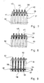
- FIG. 3 shows an embodiment similar to the subject of FIG. 3 in a partially sectioned side view.
- 26 rings or ring segments 27 are inserted into the wave troughs of a hose, from both sides of the hose in the neutral bend flat ropes 28 and 29 are crossed.
- flags 30, 31 are bent in the constant longitudinal direction of the hose 26, which, due to a curve 32, 33 formed in their course, interlock with one another in a scale-like manner with respect to adjacent rings or ring segments 27 and are thus in frictional contact with one another.
- These flags 30, 31 also have such a radial distance from the hose 26 that they cannot come into contact with its outward wave crests 34.
- Fig. 6 shows a perspective view of a ring segment 27 of the type described, on which the bores 35, 36 for the ropes 28, 29 can be seen and also the way in which the flags 30, 31 are cut out of the ring segment 27, for example made of sheet metal, and are turned.
- FIG. 7 shows a sectional side view of a design according to which rings or ring segments seated in the troughs of a hose 37 38 are placed on the outside in the manner of a bellows shaft curved attenuators 39, the are in frictional contact via axially directed flags 40, 41, the flags being arranged essentially tangentially to the hose 37 in the present case.
- the damping members 39 can again be expediently arranged individual parts distributed symmetrically over the circumference of the hose. However, a closed, circumferential design is also conceivable. In particular for damping members 39 consisting of individual parts, it is expedient to bring them into locking engagement with a corresponding bore 43 of the rings or ring segments 38 via a constriction 42.
- FIG. 8 shows a design comparable to FIG. 7 for a hose 44 and spacers in the form of rings or ring segments 45, but in which the damping members 46 designed in the manner of a bellows shaft are placed on the inside of the rings or ring segments 45 and are thus between them Hose 44 and rings or ring segments 45 are located. However, these damping members 46 also engage in friction with one another with axially directed flags 47, 48, without being in contact with the tube 44 at the same time with these flags. As far as the wave-shaped design of the damping members 46 is concerned, it goes without saying that this has so much freedom with respect to the wave flanks of the hose 44 that the desired one Movement of the hose is not affected.
- spacers in the form of rings or ring segments 53 are inserted into the troughs of a hose 51 on both sides of the hose in the bending plane of ropes 52, in which a pair of leaf springs 54, 55 is captively inserted in every second spacer , whose tongues 56 to 59 projecting on both sides of the spacer are bent towards one another.
- Webs 60 are inserted into the spacers therebetween, the ends of which protrude on both sides in the axial direction protrude between the respectively adjacent pair of leaf spring tongues 56, 57 and 58, 59, the tongues being bent apart and then being in frictional engagement with the webs 60 .
- both the leaf springs and the webs are arranged in the radial direction of the hose 51 so that they have no contact with the hose.
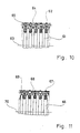
- FIG. 10 shows a design that fundamentally differs from the previous examples.
- Agreement initially consists in the fact that spacers in the form of rings or ring segments 62 are inserted into the troughs of a hose 61. However, these are buffered against each other outside the bending plane formed by the line 63 representing the hose axis, by interposed cushions 64, which can be single cushions or circular cushions, are arranged in a contact-free manner with respect to the hose 61 and for producing damped resilient properties, for example, from a knitted fabric made of metal or plastic are pressed.
- the cushions 64 maintain their position between adjacent spacers 62, bores or spacers 65 are inserted into bores of the spacers, which protrude into corresponding recesses in the cushions 64 and thereby hold them in place both in the circumferential direction and in the radial direction.
- the cushions 64 can be designed in such a way that they allow significant changes in the spacing of adjacent spacers 62, so that the hose remains free of its required mobility.
- FIG. 11 shows an embodiment similar to FIG. 10 with a hose 66 and spacers 67 in the form of rings inserted in its troughs or ring segments, a pipe piece 68 projecting on both sides, for example made of plastic, being inserted into every second ring, into which pins 69, which are received by the other spacers 67, plunge practically without play from both sides. Due to the cylinder-piston units formed in this way, adjacent spacers 67 can be moved against one another not only by frictional engagement between parts 68 and 69, but also due to the pneumatic movement brake which is established between parts 68 and 69.
- the cylinder-piston units 68, 69 are in turn contact-free with respect to the hose 66 and can be arranged with respect to each spacer 67 in a suitable manner distributed symmetrically over the circumference.
- such a sheathing is also placed on the connecting pieces of the hose, it can also at least temporarily support axial forces which can result if at least one of the ropes accompanying the hose breaks or breaks. In this way, the sheathing in such a case provides protection against subsequent tearing of the hose and the associated risk of accident.
Landscapes
- Engineering & Computer Science (AREA)
- General Engineering & Computer Science (AREA)
- Mechanical Engineering (AREA)
- Supports For Pipes And Cables (AREA)
- Rigid Pipes And Flexible Pipes (AREA)
Priority Applications (1)
| Application Number | Priority Date | Filing Date | Title |
|---|---|---|---|
| AT87109537T ATE56801T1 (de) | 1986-07-14 | 1987-07-02 | Biegbarer schlauch mit zueinander parallelen, ringfoermigen wellen und axialabstuetzung. |
Applications Claiming Priority (2)
| Application Number | Priority Date | Filing Date | Title |
|---|---|---|---|
| DE3623702A DE3623702A1 (de) | 1986-07-14 | 1986-07-14 | Biegbarer schlauch mit zueinander parallelen, ringfoermigen wellen und axialabstuetzung |
| DE3623702 | 1986-07-14 |
Publications (3)
| Publication Number | Publication Date |
|---|---|
| EP0253220A2 true EP0253220A2 (fr) | 1988-01-20 |
| EP0253220A3 EP0253220A3 (en) | 1988-09-21 |
| EP0253220B1 EP0253220B1 (fr) | 1990-09-19 |
Family
ID=6305140
Family Applications (1)
| Application Number | Title | Priority Date | Filing Date |
|---|---|---|---|
| EP87109537A Expired - Lifetime EP0253220B1 (fr) | 1986-07-14 | 1987-07-02 | Tuyau flexible ayant des cannelures annulaires parallèles et un support axial |
Country Status (3)
| Country | Link |
|---|---|
| EP (1) | EP0253220B1 (fr) |
| AT (1) | ATE56801T1 (fr) |
| DE (1) | DE3623702A1 (fr) |
Cited By (3)
| Publication number | Priority date | Publication date | Assignee | Title |
|---|---|---|---|---|
| EP0300174A1 (fr) * | 1987-07-21 | 1989-01-25 | Witzenmann GmbH Metallschlauch-Fabrik Pforzheim | Tuyau flexible à ondes parallèles et annulaires et support axial |
| EP1564400A1 (fr) * | 2004-02-12 | 2005-08-17 | Attax | Jonc de renfort notamment pour un conduit de système d'alimentation en air d'un moteur de véhicule automobile |
| CN108758118A (zh) * | 2018-08-13 | 2018-11-06 | 宁波欧佩亚海洋工程装备有限公司 | 一种深海柔性复合管 |
Families Citing this family (1)
| Publication number | Priority date | Publication date | Assignee | Title |
|---|---|---|---|---|
| DE202006008578U1 (de) * | 2006-05-30 | 2007-10-11 | Veritas Ag | Stabilisierungselement für einen Wellschlauch |
Family Cites Families (7)
| Publication number | Priority date | Publication date | Assignee | Title |
|---|---|---|---|---|
| DE835379C (de) * | 1949-07-21 | 1952-03-31 | Heinz Bernhard Dipl Ing | Metallschlauchkompensator |
| US2894535A (en) * | 1955-09-26 | 1959-07-14 | Litton Ind Of California | Flexible pressurized conduit |
| US3006662A (en) * | 1958-03-21 | 1961-10-31 | Onoda Cement Co Ltd | Flexible connecting tube for conveyance |
| HU173990B (hu) * | 1976-06-29 | 1979-10-28 | Eroemue Es Halozattervezoe | Kompensator teplovogo rasshirenija s ehlastichnoj shtangovoj sistemoj |
| DE3671091D1 (de) * | 1985-02-04 | 1990-06-13 | Witzenmann Metallschlauchfab | Biegbares wellrohr mit zueinander parallelen, ringfoermigen wellen und axialabstuetzung. |
| DE3522334A1 (de) * | 1985-06-22 | 1987-01-02 | Witzenmann Metallschlauchfab | Biegbarer schlauch mit zueinander parallelen, ringfoermigen wellen und axialanstuetzung |
| DE8518194U1 (de) * | 1985-06-22 | 1985-09-12 | Witzenmann GmbH, Metallschlauch-Fabrik Pforzheim, 7530 Pforzheim | Biegbarer, fluiddichter Schlauch oder Balg mit einer Umhüllung zur Längsabstützung |
-
1986
- 1986-07-14 DE DE3623702A patent/DE3623702A1/de not_active Withdrawn
-
1987
- 1987-07-02 EP EP87109537A patent/EP0253220B1/fr not_active Expired - Lifetime
- 1987-07-02 AT AT87109537T patent/ATE56801T1/de not_active IP Right Cessation
Cited By (4)
| Publication number | Priority date | Publication date | Assignee | Title |
|---|---|---|---|---|
| EP0300174A1 (fr) * | 1987-07-21 | 1989-01-25 | Witzenmann GmbH Metallschlauch-Fabrik Pforzheim | Tuyau flexible à ondes parallèles et annulaires et support axial |
| EP1564400A1 (fr) * | 2004-02-12 | 2005-08-17 | Attax | Jonc de renfort notamment pour un conduit de système d'alimentation en air d'un moteur de véhicule automobile |
| FR2866394A1 (fr) * | 2004-02-12 | 2005-08-19 | Attax | Jonc de renfort notamment pour un conduit de systeme d'alimentation en air d'un moteur de vehicule automobile |
| CN108758118A (zh) * | 2018-08-13 | 2018-11-06 | 宁波欧佩亚海洋工程装备有限公司 | 一种深海柔性复合管 |
Also Published As
| Publication number | Publication date |
|---|---|
| ATE56801T1 (de) | 1990-10-15 |
| DE3623702A1 (de) | 1988-01-21 |
| EP0253220A3 (en) | 1988-09-21 |
| EP0253220B1 (fr) | 1990-09-19 |
Similar Documents
| Publication | Publication Date | Title |
|---|---|---|
| EP0210271B1 (fr) | Tuyau ondule flexible avec ondes annulaires paralleles les unes aux autres et support axial | |
| EP0670619B1 (fr) | Remplacement pour chaíne de guidage pour câbles | |
| EP2976548B1 (fr) | Chaîne de transport d'énergie destinée en particulier à des utilisations en salle blanche | |
| EP2274527B1 (fr) | Corps articulé élastique pour ensemble d'arbres | |
| DE20002820U1 (de) | Energieführungskette | |
| DE112010001295T5 (de) | Langstruktur für bewegliches Teil | |
| WO2002086349A1 (fr) | Chaine de guidage d'elements de transport d'energie | |
| EP0300174A1 (fr) | Tuyau flexible à ondes parallèles et annulaires et support axial | |
| DE2708538C3 (de) | Verbindung zwischen den Kettengliedern einer Gleiskette | |
| EP0253220B1 (fr) | Tuyau flexible ayant des cannelures annulaires parallèles et un support axial | |
| DE102016120313B4 (de) | Energieführungskette mit Verstärkungselement | |
| DE3522334A1 (de) | Biegbarer schlauch mit zueinander parallelen, ringfoermigen wellen und axialanstuetzung | |
| DE2851708B2 (de) | Verbindungsorgan für ein Lastgehänge | |
| DE10201801C2 (de) | Flexible Verbindungseinrichtung für zwei Rohrteile, insbesondere bei Abgasanlagen von Kraftfahrzeugen | |
| DE2543579C3 (de) | Streckwerks-Walzenbezug | |
| DE102018114520B4 (de) | Leitungsführungselement und Maschinenvorrichtung | |
| EP1849723B1 (fr) | Chaîne transporteuse | |
| EP1619364B1 (fr) | Antivibrateur | |
| DE102020202461A1 (de) | Energieführungssystem für flexible Energieleiter | |
| DE4420203C2 (de) | Kettenschloß für Rundgliederketten | |
| EP2546175B1 (fr) | Dispositif de transport | |
| DE3724538C2 (fr) | ||
| DE2600270C2 (de) | Elastische Kupplung | |
| AT389928B (de) | Kette mit aus rundmaterial geschweissten kettengliedern | |
| DE1212370B (de) | Flexibles metallisches Gliederrohr zur Aufnahme von flexiblen Schlaeuchen, Kabeln od. dgl. |
Legal Events
| Date | Code | Title | Description |
|---|---|---|---|
| PUAI | Public reference made under article 153(3) epc to a published international application that has entered the european phase |
Free format text: ORIGINAL CODE: 0009012 |
|
| AK | Designated contracting states |
Kind code of ref document: A2 Designated state(s): AT BE CH FR GB IT LI NL |
|
| PUAL | Search report despatched |
Free format text: ORIGINAL CODE: 0009013 |
|
| AK | Designated contracting states |
Kind code of ref document: A3 Designated state(s): AT BE CH FR GB IT LI NL |
|
| 17P | Request for examination filed |
Effective date: 19881024 |
|
| 17Q | First examination report despatched |
Effective date: 19891110 |
|
| GRAA | (expected) grant |
Free format text: ORIGINAL CODE: 0009210 |
|
| AK | Designated contracting states |
Kind code of ref document: B1 Designated state(s): AT BE CH FR GB IT LI NL |
|
| PG25 | Lapsed in a contracting state [announced via postgrant information from national office to epo] |
Ref country code: NL Effective date: 19900919 Ref country code: BE Effective date: 19900919 |
|
| REF | Corresponds to: |
Ref document number: 56801 Country of ref document: AT Date of ref document: 19901015 Kind code of ref document: T |
|
| GBT | Gb: translation of ep patent filed (gb section 77(6)(a)/1977) | ||
| ITF | It: translation for a ep patent filed | ||
| ET | Fr: translation filed | ||
| K2 | Correction of patent specification published | ||
| NLV1 | Nl: lapsed or annulled due to failure to fulfill the requirements of art. 29p and 29m of the patents act | ||
| PGFP | Annual fee paid to national office [announced via postgrant information from national office to epo] |
Ref country code: FR Payment date: 19910429 Year of fee payment: 5 |
|
| PGFP | Annual fee paid to national office [announced via postgrant information from national office to epo] |
Ref country code: GB Payment date: 19910612 Year of fee payment: 5 |
|
| PLBE | No opposition filed within time limit |
Free format text: ORIGINAL CODE: 0009261 |
|
| STAA | Information on the status of an ep patent application or granted ep patent |
Free format text: STATUS: NO OPPOSITION FILED WITHIN TIME LIMIT |
|
| PGFP | Annual fee paid to national office [announced via postgrant information from national office to epo] |
Ref country code: CH Payment date: 19910724 Year of fee payment: 5 |
|
| PGFP | Annual fee paid to national office [announced via postgrant information from national office to epo] |
Ref country code: AT Payment date: 19910725 Year of fee payment: 5 |
|
| ITTA | It: last paid annual fee | ||
| 26N | No opposition filed | ||
| PG25 | Lapsed in a contracting state [announced via postgrant information from national office to epo] |
Ref country code: GB Effective date: 19920702 Ref country code: AT Effective date: 19920702 |
|
| PG25 | Lapsed in a contracting state [announced via postgrant information from national office to epo] |
Ref country code: LI Effective date: 19920731 Ref country code: CH Effective date: 19920731 |
|
| GBPC | Gb: european patent ceased through non-payment of renewal fee |
Effective date: 19920702 |
|
| PG25 | Lapsed in a contracting state [announced via postgrant information from national office to epo] |
Ref country code: FR Effective date: 19930331 |
|
| REG | Reference to a national code |
Ref country code: CH Ref legal event code: PL |
|
| REG | Reference to a national code |
Ref country code: FR Ref legal event code: ST |
|
| PG25 | Lapsed in a contracting state [announced via postgrant information from national office to epo] |
Ref country code: IT Free format text: LAPSE BECAUSE OF NON-PAYMENT OF DUE FEES;WARNING: LAPSES OF ITALIAN PATENTS WITH EFFECTIVE DATE BEFORE 2007 MAY HAVE OCCURRED AT ANY TIME BEFORE 2007. THE CORRECT EFFECTIVE DATE MAY BE DIFFERENT FROM THE ONE RECORDED. Effective date: 20050702 |