EP0300174A1 - Tuyau flexible à ondes parallèles et annulaires et support axial - Google Patents
Tuyau flexible à ondes parallèles et annulaires et support axial Download PDFInfo
- Publication number
- EP0300174A1 EP0300174A1 EP88108748A EP88108748A EP0300174A1 EP 0300174 A1 EP0300174 A1 EP 0300174A1 EP 88108748 A EP88108748 A EP 88108748A EP 88108748 A EP88108748 A EP 88108748A EP 0300174 A1 EP0300174 A1 EP 0300174A1
- Authority
- EP
- European Patent Office
- Prior art keywords
- hose
- halves
- ropes
- ring
- hose according
- Prior art date
- Legal status (The legal status is an assumption and is not a legal conclusion. Google has not performed a legal analysis and makes no representation as to the accuracy of the status listed.)
- Granted
Links
- 125000006850 spacer group Chemical group 0.000 claims abstract description 5
- 210000001503 joint Anatomy 0.000 claims description 11
- 238000004026 adhesive bonding Methods 0.000 claims description 2
- 238000003466 welding Methods 0.000 claims description 2
- 238000012986 modification Methods 0.000 description 4
- 230000004048 modification Effects 0.000 description 4
- 238000005452 bending Methods 0.000 description 3
- 238000010276 construction Methods 0.000 description 2
- 230000006735 deficit Effects 0.000 description 2
- 239000000835 fiber Substances 0.000 description 2
- 238000004519 manufacturing process Methods 0.000 description 2
- 239000000463 material Substances 0.000 description 2
- 238000000034 method Methods 0.000 description 2
- 238000010521 absorption reaction Methods 0.000 description 1
- 230000015572 biosynthetic process Effects 0.000 description 1
- 230000001427 coherent effect Effects 0.000 description 1
- 230000000694 effects Effects 0.000 description 1
- 238000005304 joining Methods 0.000 description 1
- 239000002184 metal Substances 0.000 description 1
- 230000007935 neutral effect Effects 0.000 description 1
Images


Classifications
-
- F—MECHANICAL ENGINEERING; LIGHTING; HEATING; WEAPONS; BLASTING
- F16—ENGINEERING ELEMENTS AND UNITS; GENERAL MEASURES FOR PRODUCING AND MAINTAINING EFFECTIVE FUNCTIONING OF MACHINES OR INSTALLATIONS; THERMAL INSULATION IN GENERAL
- F16J—PISTONS; CYLINDERS; SEALINGS
- F16J3/00—Diaphragms; Bellows; Bellows pistons
- F16J3/04—Bellows
- F16J3/048—Bellows with guiding or supporting means
-
- F—MECHANICAL ENGINEERING; LIGHTING; HEATING; WEAPONS; BLASTING
- F16—ENGINEERING ELEMENTS AND UNITS; GENERAL MEASURES FOR PRODUCING AND MAINTAINING EFFECTIVE FUNCTIONING OF MACHINES OR INSTALLATIONS; THERMAL INSULATION IN GENERAL
- F16L—PIPES; JOINTS OR FITTINGS FOR PIPES; SUPPORTS FOR PIPES, CABLES OR PROTECTIVE TUBING; MEANS FOR THERMAL INSULATION IN GENERAL
- F16L11/00—Hoses, i.e. flexible pipes
- F16L11/04—Hoses, i.e. flexible pipes made of rubber or flexible plastics
- F16L11/11—Hoses, i.e. flexible pipes made of rubber or flexible plastics with corrugated wall
- F16L11/115—Hoses, i.e. flexible pipes made of rubber or flexible plastics with corrugated wall having reinforcements not embedded in the wall
-
- F—MECHANICAL ENGINEERING; LIGHTING; HEATING; WEAPONS; BLASTING
- F16—ENGINEERING ELEMENTS AND UNITS; GENERAL MEASURES FOR PRODUCING AND MAINTAINING EFFECTIVE FUNCTIONING OF MACHINES OR INSTALLATIONS; THERMAL INSULATION IN GENERAL
- F16L—PIPES; JOINTS OR FITTINGS FOR PIPES; SUPPORTS FOR PIPES, CABLES OR PROTECTIVE TUBING; MEANS FOR THERMAL INSULATION IN GENERAL
- F16L33/00—Arrangements for connecting hoses to rigid members; Rigid hose-connectors, i.e. single members engaging both hoses
- F16L33/26—Arrangements for connecting hoses to rigid members; Rigid hose-connectors, i.e. single members engaging both hoses specially adapted for hoses made of metal
-
- F—MECHANICAL ENGINEERING; LIGHTING; HEATING; WEAPONS; BLASTING
- F16—ENGINEERING ELEMENTS AND UNITS; GENERAL MEASURES FOR PRODUCING AND MAINTAINING EFFECTIVE FUNCTIONING OF MACHINES OR INSTALLATIONS; THERMAL INSULATION IN GENERAL
- F16L—PIPES; JOINTS OR FITTINGS FOR PIPES; SUPPORTS FOR PIPES, CABLES OR PROTECTIVE TUBING; MEANS FOR THERMAL INSULATION IN GENERAL
- F16L51/00—Expansion-compensation arrangements for pipe-lines
- F16L51/02—Expansion-compensation arrangements for pipe-lines making use of a bellows or an expansible folded or corrugated tube
- F16L51/025—Expansion-compensation arrangements for pipe-lines making use of a bellows or an expansible folded or corrugated tube with several corrugations
- F16L51/027—Expansion-compensation arrangements for pipe-lines making use of a bellows or an expansible folded or corrugated tube with several corrugations with external reinforcement
Definitions
- the invention relates to a flexible hose with mutually parallel, annular shafts, terminal connecting parts and these holding against axial changes in distance, firmly connected to the connecting parts in the pulling and / or pushing direction longitudinal support means in the form of two outside of the hose to this essentially on diametrically opposite sides parallel, flexible ropes, the relative position between the hose and ropes given by spacers distributed at intervals over the length of the hose in its troughs in the form of annular disks with recesses receiving the ropes and the hose being guided and supported in the radial direction by the ropes.
- the term “ring-shaped” is not only to be understood as an annular design with respect to the shafts of the hose, but also, for example, in the form of a hose with an oval or similar cross section.
- the rope can be a wire or fiber bundle, a bendable rod, a band or band package, a link chain, an articulated string of chain links that can also be rigid, etc.
- the generic hoses which are also called bellows, are usually made of metal. Depending on the application, however, other materials, in particular plastic, are also suitable.
- the hoses are usually used for the flexible connection of two media-carrying parts to which they are connected. As is known, when the medium has an upper pressure, the hose tries to increase its length, so that it is necessary, by additional means, which are formed here by two ropes arranged outside the hose, to keep the mutual length spacing of the hose connection parts and the hose against To support kinking or breaking out sideways.
- the generic construction solves the task of supporting a hose of the type mentioned in such a way that it is no longer subject to tribological stress and can therefore achieve its own service life without any wear-related impairment by other parts with regard to the load to be absorbed, in particular the alternating bending stress.
- the ropes are generally arranged in the neutral bending plane of the hose, so that there are no relative movements with respect to the hose, neither in the longitudinal direction nor in the circumferential direction, the spacers serving to to keep the parts in the relative position to the hose.
- the spacers are essentially designed as ring disks inserted into the hose shafts, which grip the cable via bores arranged in them and thus position them relative to the hose.
- the object of the invention is to modify the design of a hose unit of the type mentioned in such a way that the problems with regard to the assembly between ropes and washers are eliminated and final assembly with the connecting pieces is made possible in a simple manner, the measures being designed at the same time in such a way that automatic assembly can also be carried out by means of appropriate assembly devices.
- this object is achieved according to the invention in that the washers consist of two identical halves and these are held together or joined together by effective means of closure without the aid of the ropes.
- the ring disc halves are combined in one form with the ropes which do not require the connection of the frictional connection or the positive connection with the rope itself, so that at the same time it is achieved that the rope from the closure loads how they can result from the ring disc halves is exempt.
- the measures according to the invention thus create a design which enables the ring disk halves to be inserted or put on either after the ropes have been attached between the connecting pieces or by placing the respective ropes with the ring halves assigned to them as an entire structural unit.
- the two halves of the washers along one Crossing recesses and half of this butt joint against each other.
- the ropes can be mounted between the connecting pieces independently of the washer halves, the washer halves being partly inserted beforehand into the troughs of the hose and sometimes being put on later, but in any case the ropes without the need for one Finally, thread the threading process and without impairing the laying of the ropes between the connecting pieces from the inside and from the outside.
- each half of the ring disks starting from their ends located in the area of the ropes, each have a tangentially extending flag covering the other half of the ring disk, and that each recess of the ring disk halves for the ropes has a corresponding one in the longitudinal direction of the associated one Flag-extending slot is open to the outside from the width of the rope cross-section.
- each rope is divided into two adjacent rope strands and that the two halves ten of the washers are set against each other along a butt joint between the rope strands.
- ring disc halves can be equipped with corresponding "rope halves" in order to then place them on the hose in opposite directions, ie from two opposite sides.
- the ring disk halves come into supporting contact with one another so that circumferential stresses can be absorbed.
- a further embodiment of the invention can, however, also consist in that the two halves of the annular disks are placed against one another along a butt joint located outside the recesses.
- ring washer halves can be equipped with the ropes assigned to them and then placed against the hose as a complete structural unit.
- the recesses of the ring disk halves are closed bores.
- the recesses of the ring disc halves are open radially inwards, so that the ring disc halves can only be put on from the outside at the end after the cables have been laid.
- the ring disc halves are held together by an externally positively placed ring and that the ring is held by the positive locking against lateral slipping off the ring disc halves.
- a ring which holds the ring together is placed on the normally two halves of the washer and is provided with means which establish its positive connection with the halves of the washer so that it actually remains on the halves of the washer and during operation cannot slide sideways from these.
- the rings placed on the outside that adjacent rings with their side edges facing one another engage in a step-like manner.
- the mobility of adjacent rings in the axial direction of the hose is fixed to a defined dimension, which opens up the possibility of determining the bendability or the bending range of the hose according to the invention.
- the two halves of the annular disks can be designed to overlap in two areas diametrically opposite one another outside the recesses with tabs extending tangentially from them in order to achieve the effect described above.
- FIG. 1 shows in radial section a corrugated hose with an annular corrugation in the area of a corrugation trough 1, ring washer halves 2, 3 being inserted in the corrugation trough, which grips cables 4, 5 accompanying the corrugated hose at their butt joint 6 by forming this butt joint in such a way that that the washer halves 2, 3 can be placed laterally from the outside after the ropes 4, 5 have been attached.
- Figure 1 shows by dashed line 7, the crests of the corrugated hose.
- FIG. 2 a variant of the object described with reference to FIG. 1 is shown.
- ring halves 8, 9 are placed on the ropes 4, 5 in a corresponding manner, the butt joint 10 of which is also in the region of the ropes 4, 5, but the design is somewhat different from the object according to FIG. 1, as is the case here is readily apparent from the comparison of the drawings.
- FIG. 3 shows in axial section the design of a hose 13 with annular shafts 14 and cables 15 arranged axially parallel thereto, the cables being gripped by ring disk halves 16 of the type already described with reference to FIGS. 1 and 2.
- the hose 13 is provided at the end with a connector 17 to which the cables 15 are connected via a flange 18 and a socket 19.
- FIG. 4 A variant of this problem is shown in FIG. 4, in which hat-shaped rings 26 are placed there on the rings 25 of the hose 24 and at the same time create an axial movement limitation via axial extensions 27 and 28.
- FIG. 5 a simplified embodiment of the version of the ring 29 receiving ring disc halves 30 is shown, wherein the ring disc halves 30 are held by rings 31 by means of their bent lugs 32 so that the rings 31 are positively fixed on the rings 30 and these in the desired Keep it together.
- FIG. 6 an embodiment is shown in which the ropes are each divided into rope strands 33, 34 which are received by ring disk halves 35, 36, the mutual butt joint of which is passed between the two rope strands 33, 34.
- ring disk halves 35, 36 are held together by a ring 37 each encompassing them, which in principle again corresponds to the rings as described in more detail with reference to FIGS. 3-5.
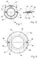
- FIG. 7 shows an embodiment in radial section in which ring halves 39, 40 are placed on a hose 38, the butt joint of which lies outside the recesses 41, 42 for cables 43 and 44 arranged parallel to the hose 38.
- a ring 45 of the type already described is again provided according to the lower half of FIG. 7, which is placed in a form-fitting manner on the ring disk halves 39, 40.
- the recesses 41 of the ring disc halves 39 and 40 in the form of radially inwardly open recesses forms can be.
- the recesses 42 can also be designed in the form of holes which are enlarged with respect to the cable cross section, so that in the end here ropes 44 with ring disk halves 39 lined up thereon are placed laterally as a kit on the hose 38 and can then be connected to a correspondingly opposite kit.
- FIG. 9 shows a ring disc halves 53, 54 placed radially in its troughs on the tube 52, each of which, starting from its ends in the area of the cables 55, 56, has a tangentially extending flag 57, 58 covering the other half of the ring disc, each recess the ring disc halves for the cables is open to the outside via the slot 59, 60, which extends in the longitudinal direction of the associated flag, from the width of the cable cross section.
- the washer halves 53, 54 can be attached radially from the outside after the ropes 55, 56 have been attached.
- adjacent ring disk halves 53, 54 are welded to one another at the locations marked by the crosses 61.
Landscapes
- Engineering & Computer Science (AREA)
- General Engineering & Computer Science (AREA)
- Mechanical Engineering (AREA)
- Supports For Pipes And Cables (AREA)
- Rigid Pipes And Flexible Pipes (AREA)
Applications Claiming Priority (2)
| Application Number | Priority Date | Filing Date | Title |
|---|---|---|---|
| DE3724069 | 1987-07-21 | ||
| DE3724069A DE3724069C1 (de) | 1987-07-21 | 1987-07-21 | Biegbarer Schlauch mit zueinander parallelen ringfoermigen Wellen und Axialabstuetzung |
Publications (2)
| Publication Number | Publication Date |
|---|---|
| EP0300174A1 true EP0300174A1 (fr) | 1989-01-25 |
| EP0300174B1 EP0300174B1 (fr) | 1990-08-29 |
Family
ID=6332011
Family Applications (1)
| Application Number | Title | Priority Date | Filing Date |
|---|---|---|---|
| EP88108748A Expired - Lifetime EP0300174B1 (fr) | 1987-07-21 | 1988-06-01 | Tuyau flexible à ondes parallèles et annulaires et support axial |
Country Status (5)
| Country | Link |
|---|---|
| US (1) | US4911206A (fr) |
| EP (1) | EP0300174B1 (fr) |
| DE (2) | DE3724069C1 (fr) |
| ES (1) | ES2017004B3 (fr) |
| IL (1) | IL86738A0 (fr) |
Cited By (2)
| Publication number | Priority date | Publication date | Assignee | Title |
|---|---|---|---|---|
| EP0448769A1 (fr) * | 1990-03-27 | 1991-10-02 | Anamet Inc. | Raccord insonorisant et flexible pour conduits d'échappement |
| EP2146125A1 (fr) * | 2008-07-17 | 2010-01-20 | Nexans | Conduite flexible |
Families Citing this family (30)
| Publication number | Priority date | Publication date | Assignee | Title |
|---|---|---|---|---|
| US5273321A (en) * | 1992-05-26 | 1993-12-28 | Richter James R | Flexible connector with integral flexible extension controls |
| DE4410706C2 (de) * | 1994-03-28 | 1998-12-10 | Murrplastik Systemtechnik Gmbh | Wellenschlauch |
| KR960006037Y1 (ko) * | 1994-12-28 | 1996-07-20 | 성진기공 주식회사 | 배기관용 연결구 |
| DE19509116C2 (de) * | 1995-03-16 | 2000-01-05 | Deutsch Zentr Luft & Raumfahrt | Flexible Struktur |
| RU2140035C1 (ru) * | 1997-02-06 | 1999-10-20 | Производственное объединение "Северное машиностроительное предприятие" | Шланг металлический |
| US5791379A (en) * | 1997-05-23 | 1998-08-11 | Piorkowski; Michael J. | Pipe cage |
| US5996640A (en) * | 1998-05-22 | 1999-12-07 | Tseng; Shao-Chien | DIY flexible pipe with rigidity |
| US6705311B1 (en) * | 2001-11-13 | 2004-03-16 | Solel Solar Systems Ltd. | Radiation heat-shield for solar system |
| US7080858B2 (en) * | 2003-11-06 | 2006-07-25 | The Goodyear Tire & Rubber Company | Seawater suction hose and method |
| US8182176B2 (en) * | 2008-11-21 | 2012-05-22 | Lockheed Martin Corporation | Tendon-supported membrane pipe |
| US8444182B2 (en) * | 2010-11-04 | 2013-05-21 | Sea Energy Technology Co, Ltd. | Water intake pipe of ocean thermal energy conversion power plant |
| FR2971575B1 (fr) * | 2011-02-11 | 2013-12-13 | Snecma | Element de conduit a perte de charge reduite |
| US20120318371A1 (en) * | 2011-06-17 | 2012-12-20 | Caterpillar Inc. | Bellows assembly and engaging structure |
| US10557550B2 (en) * | 2015-04-10 | 2020-02-11 | Mide Technology Corporation | Flexible joint |
| US10898929B2 (en) * | 2015-08-10 | 2021-01-26 | Dematic S.R.L. | Bellows connecting adjacent carriages, in particular carriages of a material handling sorter |
| DE102018206614A1 (de) * | 2018-04-27 | 2019-10-31 | Sgl Carbon Se | Vakuumstützring |
| CN109058589B (zh) * | 2018-08-15 | 2023-04-07 | 福州大学 | 一种轻质柔性管路的减振吊架装置及其成型工艺 |
| US12194620B2 (en) | 2018-10-15 | 2025-01-14 | Oliver Crisipin Robotics Limited | Selectively flexible extension tool |
| US11707819B2 (en) | 2018-10-15 | 2023-07-25 | General Electric Company | Selectively flexible extension tool |
| US11702955B2 (en) | 2019-01-14 | 2023-07-18 | General Electric Company | Component repair system and method |
| US10865920B2 (en) * | 2019-02-01 | 2020-12-15 | Caterpillar Inc. | Exhaust bellows installation tool |
| US12405187B2 (en) | 2019-10-04 | 2025-09-02 | General Electric Company | Insertion apparatus for use with rotary machines |
| US11692650B2 (en) | 2020-01-23 | 2023-07-04 | General Electric Company | Selectively flexible extension tool |
| US11752622B2 (en) | 2020-01-23 | 2023-09-12 | General Electric Company | Extension tool having a plurality of links |
| US11613003B2 (en) | 2020-01-24 | 2023-03-28 | General Electric Company | Line assembly for an extension tool having a plurality of links |
| US11371437B2 (en) | 2020-03-10 | 2022-06-28 | Oliver Crispin Robotics Limited | Insertion tool |
| US12091981B2 (en) | 2020-06-11 | 2024-09-17 | General Electric Company | Insertion tool and method |
| US12504616B2 (en) | 2021-01-08 | 2025-12-23 | General Electric Company | Insertion tool |
| US12416800B2 (en) | 2021-01-08 | 2025-09-16 | General Electric Company | Insertion tool |
| US11654547B2 (en) | 2021-03-31 | 2023-05-23 | General Electric Company | Extension tool |
Citations (3)
| Publication number | Priority date | Publication date | Assignee | Title |
|---|---|---|---|---|
| WO1986004660A1 (fr) * | 1985-02-04 | 1986-08-14 | Witzenmann Gmbh Metallschlauch-Fabrik Pforzheim | Tuyau flexible avec ondes annulaires paralleles les unes aux autres et support axial |
| DE3522334A1 (de) * | 1985-06-22 | 1987-01-02 | Witzenmann Metallschlauchfab | Biegbarer schlauch mit zueinander parallelen, ringfoermigen wellen und axialanstuetzung |
| EP0253220A2 (fr) * | 1986-07-14 | 1988-01-20 | Witzenmann GmbH Metallschlauch-Fabrik Pforzheim | Tuyau flexible ayant des cannelures annulaires parallèles et un support axial |
Family Cites Families (9)
| Publication number | Priority date | Publication date | Assignee | Title |
|---|---|---|---|---|
| US1971928A (en) * | 1932-04-01 | 1934-08-28 | James P Zallea | Duo-self-equalizing expansion joint |
| US2707117A (en) * | 1948-02-03 | 1955-04-26 | Chicago Metal Hose Corp | Reinforced flexible bellows joint |
| US2748803A (en) * | 1953-08-10 | 1956-06-05 | Titeflex Inc | Reinforced hose |
| US2894535A (en) * | 1955-09-26 | 1959-07-14 | Litton Ind Of California | Flexible pressurized conduit |
| FR2080195A5 (fr) * | 1970-02-26 | 1971-11-12 | Stein Industrie | |
| BE791932A (fr) * | 1972-07-22 | 1973-03-16 | Italiana Comp | Compensateur de dilatation pour les deplacements angulaires importants |
| IT1092995B (it) * | 1978-03-03 | 1985-07-12 | Tecnomare Spa | Condotta flessibile a struttura composita per il risucchio di grandi quantita' di acqua di mare da alte profondita |
| US4497342A (en) * | 1983-06-20 | 1985-02-05 | Lockheed Missiles & Space Company, Inc. | Flexible retractable cold water pipe for an ocean thermal energy conversion system |
| US4686963A (en) * | 1986-03-05 | 1987-08-18 | Circon Corporation | Torsion resistant vertebrated probe of simple construction |
-
1987
- 1987-07-21 DE DE3724069A patent/DE3724069C1/de not_active Expired
-
1988
- 1988-06-01 DE DE8888108748T patent/DE3860523D1/de not_active Expired - Lifetime
- 1988-06-01 ES ES88108748T patent/ES2017004B3/es not_active Expired - Lifetime
- 1988-06-01 EP EP88108748A patent/EP0300174B1/fr not_active Expired - Lifetime
- 1988-06-14 IL IL86738A patent/IL86738A0/xx unknown
- 1988-06-24 US US07/211,350 patent/US4911206A/en not_active Expired - Fee Related
Patent Citations (3)
| Publication number | Priority date | Publication date | Assignee | Title |
|---|---|---|---|---|
| WO1986004660A1 (fr) * | 1985-02-04 | 1986-08-14 | Witzenmann Gmbh Metallschlauch-Fabrik Pforzheim | Tuyau flexible avec ondes annulaires paralleles les unes aux autres et support axial |
| DE3522334A1 (de) * | 1985-06-22 | 1987-01-02 | Witzenmann Metallschlauchfab | Biegbarer schlauch mit zueinander parallelen, ringfoermigen wellen und axialanstuetzung |
| EP0253220A2 (fr) * | 1986-07-14 | 1988-01-20 | Witzenmann GmbH Metallschlauch-Fabrik Pforzheim | Tuyau flexible ayant des cannelures annulaires parallèles et un support axial |
Cited By (2)
| Publication number | Priority date | Publication date | Assignee | Title |
|---|---|---|---|---|
| EP0448769A1 (fr) * | 1990-03-27 | 1991-10-02 | Anamet Inc. | Raccord insonorisant et flexible pour conduits d'échappement |
| EP2146125A1 (fr) * | 2008-07-17 | 2010-01-20 | Nexans | Conduite flexible |
Also Published As
| Publication number | Publication date |
|---|---|
| IL86738A0 (en) | 1988-11-30 |
| EP0300174B1 (fr) | 1990-08-29 |
| US4911206A (en) | 1990-03-27 |
| ES2017004B3 (es) | 1990-12-16 |
| DE3724069C1 (de) | 1989-03-16 |
| DE3860523D1 (de) | 1990-10-04 |
Similar Documents
| Publication | Publication Date | Title |
|---|---|---|
| EP0300174B1 (fr) | Tuyau flexible à ondes parallèles et annulaires et support axial | |
| EP0210271B1 (fr) | Tuyau ondule flexible avec ondes annulaires paralleles les unes aux autres et support axial | |
| DE3903355C2 (fr) | ||
| DE3640226C2 (fr) | ||
| EP2839197B1 (fr) | Collier de serrage et raccord tubulaire pour la liaison de force de tuyaux, en particulier de tuyaux à extrémités lisses | |
| EP3195434A1 (fr) | Dispositif de guidage de lignes, destiné en particulier à des applications en salle blanche, éléments de coque, et carcasse de support afférente | |
| DE3018119C2 (de) | Mit Zugentlastung versehene Kabeleinführung für Gehäuse elektrischer Maschinen und Geräte | |
| DE2059576B2 (de) | Steckkupplung für mehradrige hydraulische oder pneumatische Kabel | |
| EP0521822B1 (fr) | Dispositif pour le raccordement de deux gaines | |
| EP3314148B1 (fr) | Chaîne porte-câbles | |
| EP0709558A1 (fr) | Elément de conduit pour la conduite des gaz d'échappement d'un moteur à combustion interne | |
| DE69111356T2 (de) | Treibkette. | |
| DE1817855B2 (de) | Kupplung für Abschnitte einer Kabelhülle bei einer Einrichtung zur Bewegungsübertragung mittels zweier gegenläufiger Zugkabel | |
| DE2327050B1 (de) | Rohrverbindung | |
| DE3104518A1 (de) | Anschlussarmatur | |
| DE3522334A1 (de) | Biegbarer schlauch mit zueinander parallelen, ringfoermigen wellen und axialanstuetzung | |
| EP1289087A2 (fr) | Elément de fermeture et d'étanchéisation | |
| DE4422985C2 (de) | Verfahren und Anordnung zum Befestigen eines Wellrohres und eines Ziehpfropfens aneinander sowie Wellrohr und Ziehpfropfen dafür | |
| EP0396927B1 (fr) | Elément de connexion, respectivement de liaison pour harnais de câbles | |
| DE4410706C2 (de) | Wellenschlauch | |
| EP1265021B1 (fr) | Capuchon de protection | |
| DE8709907U1 (de) | Vorrichtung zum Einziehen von Kabeln in Kabelschutzrohre | |
| DE2012631A1 (de) | Längsgeteilte Kabelmuffe mit Kabelabfangung | |
| DE3504978A1 (de) | Spannmuffe | |
| EP1265020A2 (fr) | Conduite flexible de gaz |
Legal Events
| Date | Code | Title | Description |
|---|---|---|---|
| PUAI | Public reference made under article 153(3) epc to a published international application that has entered the european phase |
Free format text: ORIGINAL CODE: 0009012 |
|
| AK | Designated contracting states |
Kind code of ref document: A1 Designated state(s): CH DE ES FR GB IT LI |
|
| 17P | Request for examination filed |
Effective date: 19890110 |
|
| 17Q | First examination report despatched |
Effective date: 19890622 |
|
| GRAA | (expected) grant |
Free format text: ORIGINAL CODE: 0009210 |
|
| AK | Designated contracting states |
Kind code of ref document: B1 Designated state(s): CH DE ES FR GB IT LI |
|
| ITF | It: translation for a ep patent filed | ||
| REF | Corresponds to: |
Ref document number: 3860523 Country of ref document: DE Date of ref document: 19901004 |
|
| GBT | Gb: translation of ep patent filed (gb section 77(6)(a)/1977) | ||
| ET | Fr: translation filed | ||
| PGFP | Annual fee paid to national office [announced via postgrant information from national office to epo] |
Ref country code: FR Payment date: 19910429 Year of fee payment: 4 |
|
| PGFP | Annual fee paid to national office [announced via postgrant information from national office to epo] |
Ref country code: ES Payment date: 19910522 Year of fee payment: 4 |
|
| PGFP | Annual fee paid to national office [announced via postgrant information from national office to epo] |
Ref country code: CH Payment date: 19910625 Year of fee payment: 4 |
|
| PGFP | Annual fee paid to national office [announced via postgrant information from national office to epo] |
Ref country code: DE Payment date: 19910628 Year of fee payment: 4 |
|
| PLBE | No opposition filed within time limit |
Free format text: ORIGINAL CODE: 0009261 |
|
| STAA | Information on the status of an ep patent application or granted ep patent |
Free format text: STATUS: NO OPPOSITION FILED WITHIN TIME LIMIT |
|
| ITTA | It: last paid annual fee | ||
| 26N | No opposition filed | ||
| PG25 | Lapsed in a contracting state [announced via postgrant information from national office to epo] |
Ref country code: GB Effective date: 19920601 |
|
| PG25 | Lapsed in a contracting state [announced via postgrant information from national office to epo] |
Ref country code: ES Free format text: LAPSE BECAUSE OF THE APPLICANT RENOUNCES Effective date: 19920602 |
|
| PG25 | Lapsed in a contracting state [announced via postgrant information from national office to epo] |
Ref country code: LI Effective date: 19920630 Ref country code: CH Effective date: 19920630 |
|
| GBPC | Gb: european patent ceased through non-payment of renewal fee |
Effective date: 19920601 |
|
| PG25 | Lapsed in a contracting state [announced via postgrant information from national office to epo] |
Ref country code: FR Effective date: 19930226 |
|
| REG | Reference to a national code |
Ref country code: CH Ref legal event code: PL |
|
| PG25 | Lapsed in a contracting state [announced via postgrant information from national office to epo] |
Ref country code: DE Effective date: 19930302 |
|
| REG | Reference to a national code |
Ref country code: FR Ref legal event code: ST |
|
| REG | Reference to a national code |
Ref country code: ES Ref legal event code: FD2A Effective date: 19991007 |
|
| PG25 | Lapsed in a contracting state [announced via postgrant information from national office to epo] |
Ref country code: IT Free format text: LAPSE BECAUSE OF NON-PAYMENT OF DUE FEES;WARNING: LAPSES OF ITALIAN PATENTS WITH EFFECTIVE DATE BEFORE 2007 MAY HAVE OCCURRED AT ANY TIME BEFORE 2007. THE CORRECT EFFECTIVE DATE MAY BE DIFFERENT FROM THE ONE RECORDED. Effective date: 20050601 |