EP0253243A1 - Réflecteur pour projecteur automobile à feux de route améliorés - Google Patents
Réflecteur pour projecteur automobile à feux de route améliorés Download PDFInfo
- Publication number
- EP0253243A1 EP0253243A1 EP87109641A EP87109641A EP0253243A1 EP 0253243 A1 EP0253243 A1 EP 0253243A1 EP 87109641 A EP87109641 A EP 87109641A EP 87109641 A EP87109641 A EP 87109641A EP 0253243 A1 EP0253243 A1 EP 0253243A1
- Authority
- EP
- European Patent Office
- Prior art keywords
- reflector
- reflective
- bevel cut
- rays
- plane
- Prior art date
- Legal status (The legal status is an assumption and is not a legal conclusion. Google has not performed a legal analysis and makes no representation as to the accuracy of the status listed.)
- Granted
Links
- 230000003287 optical effect Effects 0.000 claims abstract description 8
- 238000001465 metallisation Methods 0.000 claims description 14
- 238000000034 method Methods 0.000 claims description 6
- 230000008569 process Effects 0.000 claims description 4
- 230000000750 progressive effect Effects 0.000 claims description 3
- 230000001681 protective effect Effects 0.000 claims description 3
- 230000000630 rising effect Effects 0.000 claims description 3
- 238000005266 casting Methods 0.000 claims 2
- 230000001680 brushing effect Effects 0.000 claims 1
- 239000004744 fabric Substances 0.000 claims 1
- 239000003973 paint Substances 0.000 claims 1
- 238000005286 illumination Methods 0.000 description 5
- 230000001588 bifunctional effect Effects 0.000 description 4
- 230000003014 reinforcing effect Effects 0.000 description 4
- 238000000465 moulding Methods 0.000 description 3
- 239000007787 solid Substances 0.000 description 3
- 230000015572 biosynthetic process Effects 0.000 description 2
- 238000010276 construction Methods 0.000 description 2
- 230000004907 flux Effects 0.000 description 2
- 238000004519 manufacturing process Methods 0.000 description 2
- 239000000463 material Substances 0.000 description 2
- 238000004804 winding Methods 0.000 description 2
- 238000004026 adhesive bonding Methods 0.000 description 1
- 230000008901 benefit Effects 0.000 description 1
- 239000003795 chemical substances by application Substances 0.000 description 1
- 230000001419 dependent effect Effects 0.000 description 1
- 238000009826 distribution Methods 0.000 description 1
- 238000010422 painting Methods 0.000 description 1
- 238000011084 recovery Methods 0.000 description 1
- 239000007921 spray Substances 0.000 description 1
- 238000003892 spreading Methods 0.000 description 1
- 230000007480 spreading Effects 0.000 description 1
- 239000000126 substance Substances 0.000 description 1
- 239000013589 supplement Substances 0.000 description 1
- 238000003466 welding Methods 0.000 description 1
Images




Classifications
-
- F—MECHANICAL ENGINEERING; LIGHTING; HEATING; WEAPONS; BLASTING
- F21—LIGHTING
- F21S—NON-PORTABLE LIGHTING DEVICES; SYSTEMS THEREOF; VEHICLE LIGHTING DEVICES SPECIALLY ADAPTED FOR VEHICLE EXTERIORS
- F21S41/00—Illuminating devices specially adapted for vehicle exteriors, e.g. headlamps
- F21S41/30—Illuminating devices specially adapted for vehicle exteriors, e.g. headlamps characterised by reflectors
- F21S41/32—Optical layout thereof
- F21S41/33—Multi-surface reflectors, e.g. reflectors with facets or reflectors with portions of different curvature
- F21S41/338—Multi-surface reflectors, e.g. reflectors with facets or reflectors with portions of different curvature the reflector having surface portions added to its general concavity
Definitions
- the invention relates to a reflector for motor vehicle headlights with a reflective quadric, which has essentially the shape of a paraboloid of revolution and is cut by an upper and a lower bevel cut plane, with a filament filament is arranged essentially in the focus of the quadric to illuminate the road with high beam by reflection of the light rays emitted by the filament on said quadrant and through an optical cover plate which is arranged in front of this quadrant.
- optical reflectors are used to improve the drag coefficient and the styling of the motor vehicles, the reflective quadrant of which is greatly reduced in height by two bevel cut planes, not all of the lamp emitted incident useful rays as it would be useful for the functions to be ensured.
- the invention aims to improve the high beam of headlights of the type described in the introduction.
- the reflector according to the invention is characterized in that at least its lower bevel cut plane is provided on its inner surface illuminated by the high-beam filament of the incandescent lamp with a plurality of reflective spherical elements which, according to a concentric arrangement comparable to ring lenses, with respect to their common, through the focal point of the usable reflecting conical section of the reflector extending axis, wherein this focal point is also their common center of curvature.
- the concentrically staggered reflective spherical elements on the bevel cut plane with respect to their center of curvature coinciding with the focal point of the reflective quadrant of the reflector have evolute-like rays for the ring-shaped propagation from a constant division in the direction of the opening plane of the reflector and the boundary of the bevel cut plane, wherein the non-reflecting bevels of each groove of the prismatic part thus formed on the bevel cut plane are realized so that each boundary beam emitted by the lamp illuminating the bottom of the groove is returned toward the lamp without painting the offset plane of these bevels.
- the reflective spherical elements which are concentrically stepped on the bevel cut plane, have constant evolute-shaped rays with respect to their common center of curvature coinciding with the focal point of the reflective quadrant of the reflector for the ring-shaped spreading of a variable progressive division in the direction of the opening of the reflector and the boundary of the bevel cut plane the reflection of each captured ray cannot sweep the offset flank of the corresponding slopes of each optical concentric groove formed.
- the reflective spherical elements which are concentrically stepped on the bevel cut plane have evolute-shaped rays increasing in relation to their common center of curvature coinciding with the focal point of the reflective quadrant of the reflector, as they have a variable division and a constant height
- the reflective spherical elements which are illuminated by the incident useful rays emitted by the high-beam filament of the lamp, the rays reflected by the named areas not covering the offset oblique flanks of the groove produced.
- This latter characteristic represents an advantage insofar as the reflective spherical elements can be graded less closely, this method at least making it possible to realize at least one groove for two substantially while maintaining the same useful reflection volume of the recuperator device according to the invention.
- the reflector is characterized in that each reflecting surface of its stepped spherical elements of the reflector consists of a series of individually aligned microfacets, so that the incident rays, captured low and / or high beam rays, which they bring to the usable surface of the conic section Quadrik must send back, with a reflection angle softening are reflected, so that these reflected rays avoid crossing the lamp bulb and after a second reflection through the corresponding area of the usable reflecting surface of the reflector conical section complete and standardize the basic ray bundle, which was obtained by reflection only from the rays of the light source, which immediately reflect the reflecting Illuminate the surface of the main conic section of the reflector.
- the series, the dimensional development and alignment of the reflecting microfacets determine all or part of the graded elements and the entire reflecting surface of each of the steps or part thereof, a monotonous evolute surface.
- the reflector is characterized in that it is at least involved in the metallization and protection process at least one rear opening between the reflective quadrilateral and an oblique section plane is provided with stepped reflective spherical elements.
- Such an opening enables the graduated reflective surfaces facing the rear of the reflector to be sprayed with substances suspend, which are intended to carry out the metallization and then the protection of the reflector in the course of appropriate procedures. It also helps cool the projector.
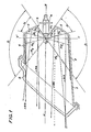
- the reflector 1 of the headlight is closed at the front by a disc 2 and takes in a rear opening 3 a monofunctional lamp 4, whose light-emitting thread is arranged strictly in the ratio 1/3 to 2/3 running length with respect to the focal point F of the reflecting quadrilateral 5 on the focal axis x ⁇ x so that the divergent-convergent high beam is generated.
- the spread of the boundary rays R1 and R2, which are emitted by the last turn or the first turn, are shown in order to limit the solid angle ⁇ in the vertical focal plane corresponding to the plane of the figure, and to limit the usable lighting area of the quadric 5, which in the absence of Recuperator elements according to the invention can be exploited and in particular depend on the diameter of the lamp opening 3 and the maximum usable working height of the cover plate 2 on the one hand, on the other hand from the usable height of the quadric 5, which emits the beam R3, emitted by the winding of the thread arranged in the focal point F, in parallel reflect to the x ⁇ x axis and can ensure that it reaches the lens without being diverted through the closest bevel cut plane.
- the stepped spherical elements or mirrors 6 and 7 according to the invention on the inner upper or lower wall of the reflector are concentric with respect to their common axis y ⁇ y by their common center of curvature coinciding with the focal point F of the reflection square 5 of the reflector.
- Their division and their rays develop according to one of the specified secondary characteristics for the formation of reflective areas or grooves, the offset slopes of which are that they form connection planes of the areas and in no way impair reception and simultaneous reflection of all boundary beams, each of which illuminates the usable areas of the spherical recuperator stages mentioned.
- the result achieved is thus an enlargement of the illumination solid angle in all segments of the reflector, where the reflective quadric 5 is reduced by the bevel cut planes (angle ⁇ in the plane of the figure), and then runs to optimize the usable illumination tion surface of the reflective quadric 5 of the reflector, which is thereby enabled to generate substantially the same luminosity as a projector which is equipped with a non-beveled reflection quadric of the same parameters.
- FIG. 2 is a longitudinal section of a bifunctional headlamp along the vertical focal plane, which here coincides with the plane of the figure.
- This bifunctional headlamp with low and high beam is equipped with a reflector of low height, in which only the lower diagonal cut plane 7 is illuminated by the high beam thread R and which is therefore provided with spherical recuperation elements according to the invention, all areas of the upper and lower diagonal cut plane, which the Use beams to form the low beam, cannot be equipped with the recuperator mirrors mentioned.
- This figure also shows the gain that the spherical recuperation elements 7 has brought to the usable illumination solid angle for the formation of the high beam in the strongly sloped lower part of the reflector 1.
- This working angle for the plane of the figure under consideration goes practically from the value ⁇ to the value ⁇ for the single turn of the high-beam filament R set to the focal point F of the quadric, and the importance of the recovered light for the entire turns of the person concerned can be easily understood
- the main beam and the totality of the sectors of the reflector should be evaluated, where the strongly slanted reflection quadrilateral could only use a small usable reflection surface in the lower part.
- FIG. 3 is a plan view of an inventive bifunctional reflector shown, which is cut along the horizontal focal plane.
- the profile of the spherical recuperator elements 7 is shown, namely in a section along the plane EFG and folded down into the plane Z ⁇ Z perpendicular to the longitudinal focal plane y ⁇ y and parallel to the plane of the illumination opening of the reflector, that is to say into the representation plane of FIG. 3.
- spherical recuperator elements according to the invention shown in the various figures are in no way exhaustive or restrictive; because these spherical recuperator elements can e.g. B. can also be realized in the thickness of the wall of the bevel cut plane concerned, which intersects the quadrilateral of the reflector, as well as raised on the inner wall of the same plane or in an optical auxiliary disk which is placed on the inner surface of the bevel cut plane of the reflector.
- This auxiliary pane can in turn come from a decorative strip or an attachment that extends the light opening of the reflector to the front, or can also be obtained from a metallized rear extension of the cover pane, which penetrates into the interior of the reflector in order to overlay the aforementioned inner wall of the predetermined diagonal cut plane.
- the spherical recuperator elements can either form concentric crowns on the entire parallel or inclined plane of the reflector truncation or, as shown in FIG. 3, be limited in the arc length, depending on the usable gain that must be achieved around the high beam to reinforce.
- the spherical recuperator elements can be manufactured on all types of reflectors with a bevel cut plane, including reflectors with evolutionary facets and / or progressive or monotonous evolutionary conic sections.
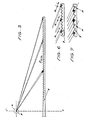
- FIG. 5 schematically shows the constant division P of the spherical elements 7 with increasing evolute rays
- FIG. 6 the constant evolute ray R of the spherical elements 7 with variable division
- FIG. 7 the constant usable height H of the usable regions of the spherical elements 7 with growing evolute rays and variable division shown.
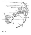
- the reflector 1 comprises a rear opening 3 for receiving a lamp 4, the filament C emits i1, i2 and incident rays i ⁇ 1, i ⁇ 2 incident to the rear.
- the rays i ⁇ 1, i ⁇ 2 are reflected on the reflector 1, which is formed by a reflection conical section 10 and whose outline of the vertical focal plane is shown at T.
- the bevel cut plane P comprises stepped spherical elements 7, which according to the invention consist of a multiplicity of microfacets 20, which are oriented in such a way that the reflected rays R1 and R2 of the incident rays i1 and i2 are reflected by the angles d1 and d2 at the conic section 10, without having crossed the bulb 4 ⁇ of the lamp 4, and in this way supplement and standardize the beam that is directly reflected by the conic section and comes from the incident rays i ⁇ 1 and i ⁇ 2. If a bilux lamp, not shown in the drawing, is used, the rays emitted by the high-beam filament are also reflected at the steps 7, without the Cross lamp 4.
- At least a portion of the microfacettes 20 define a monotonous evolute surface.
- the reflector has a lamp mounting opening 3 at the rear and an opening defining its usable luminous area at the front, which opening is strapped by a reinforcing flange with various means for fastening and adjusting the direction.
- Its reflection quadrilateral 5 on the other hand, is limited in height as a function of two bevel cut planes 27 and 28, which are provided on the inside with graduated reflection elements 6 and 7 for increasing the angle of illumination of the quadric 5.
- the reflector since the usable reflection surfaces of the stepped elements are essentially directed towards the rear - opposite to the usable main reflection surface of the quadric 5 - is provided according to the invention with two rear openings or spaces 29 and 30 which are located between the bevel cut planes 27 and 28 and the upper one and the lower limit of the quadric 5 are created, in particular to enable metallization and protection of the usable areas of the recuperator elements in an effective manner.
- the upper and lower limits of the quadric 5 are each provided directly at the rear openings 29 and 30 with a reinforcing rib 31 and 32, which stiffens the outer wall of the quadric 5 and extends it outwards.
- the edge of each bevel cut is ne outside provided with a rib 33, 34.
- each opening 29-30 is closed with a shell 35-36 made of molded material (FIG. 10), this shell preferably being attached to the Outside of the construction of the reflection quadric is that it can then be removed at least without risk of changing the polish of the inner surface of the reflector before the metallization and protection of the usable reflection surface of the quadric 5 and the graduated recuperator elements 6-7 ensue.
- the entire inner surface of the reflector, which is attached to the pivot supports of a carrier of the appropriate metallization agent, is effectively exposed to the various spray jets from the chosen metallization protection cycle are determined, in part by the front opening for the main usable area of the quadric 5, in part by the rear openings 29-30 for each of the additional usable areas of the stepped recuperator elements 6 and 7.
- the vertical size of the openings 29 and 30 are obviously dependent on the dimensions, shapes, inclinations and distance of the lens optics arranged in front of the reflector opening and on the available body volume, which is determined by the streamlined profile imparted to the carrier vehicle. Accordingly, the inclination of the bevel cut planes 27 and 28 in the rear part can be emphasized more, so that an obliquely rising surface 37 is formed, as shown as an unlimited example in FIG.
- the reflector whose bevel cut planes 27-28 provided with stepped elements 6-7 to facilitate the molding process form openings 29-30 with the main square 5 of the reflector at the end of this production stage, also has a thickness taper 39 of the wall of its connecting region in the front part of the reflector.
- This taper 39 is intended to form a relatively soft hinge, which after the metallization and protective work on the usable optical inner surfaces of the reflector makes it possible to fold down the bevel cut surfaces 27-28 at the upper and / or lower limit region of the Quadrik 5 and to hold them in this closed position by fastening them to the ribs 31-32 using any suitable means, such as, for example, by locking, welding, gluing , Brackets etc.
- the reflectors according to the invention can be accommodated in a protective housing and / or can be provided with any additional shell which is suitable for effective protection of their outer walls.
Landscapes
- Engineering & Computer Science (AREA)
- General Engineering & Computer Science (AREA)
- Non-Portable Lighting Devices Or Systems Thereof (AREA)
Applications Claiming Priority (6)
| Application Number | Priority Date | Filing Date | Title |
|---|---|---|---|
| FR8610339A FR2601754B1 (fr) | 1986-07-16 | 1986-07-16 | Reflecteur pour projecteur de vehicule automobile a faisceau route ameliore |
| FR8610339 | 1986-07-16 | ||
| FR868616319A FR2607222B2 (fr) | 1986-11-24 | 1986-11-24 | Reflecteur pour projecteur de vehicule automobile a faisceau route ameliore |
| FR8616319 | 1986-11-24 | ||
| FR8618141 | 1986-12-24 | ||
| FR868618141A FR2609147B2 (fr) | 1986-12-24 | 1986-12-24 | Reflecteur pour projecteur de vehicule automobile a faisceau route ameliore |
Publications (2)
| Publication Number | Publication Date |
|---|---|
| EP0253243A1 true EP0253243A1 (fr) | 1988-01-20 |
| EP0253243B1 EP0253243B1 (fr) | 1992-11-11 |
Family
ID=27251383
Family Applications (1)
| Application Number | Title | Priority Date | Filing Date |
|---|---|---|---|
| EP87109641A Expired - Lifetime EP0253243B1 (fr) | 1986-07-16 | 1987-07-04 | Réflecteur pour projecteur automobile à feux de route améliorés |
Country Status (5)
| Country | Link |
|---|---|
| US (1) | US4794504A (fr) |
| EP (1) | EP0253243B1 (fr) |
| JP (1) | JP2787444B2 (fr) |
| DE (1) | DE3782562D1 (fr) |
| ES (1) | ES2034996T3 (fr) |
Cited By (6)
| Publication number | Priority date | Publication date | Assignee | Title |
|---|---|---|---|---|
| FR2626347A1 (fr) * | 1988-01-22 | 1989-07-28 | Cibie Projecteurs | Projecteur a joues recuperatrices de flux, notamment pour vehicule automobile |
| EP0317291A3 (fr) * | 1987-11-18 | 1989-11-23 | Minnesota Mining And Manufacturing Company | Elément d'éclairage pour automobiles |
| FR2643974A1 (fr) * | 1989-03-03 | 1990-09-07 | Valeo Vision | Projecteur, notamment de vehicule automobile, et plus particulierement un projecteur a faisceau coupe |
| EP2051002A3 (fr) * | 2007-10-19 | 2010-06-02 | Stanley Electric Co., Ltd. | Phare de véhicule |
| DE102004017545B4 (de) * | 2004-04-08 | 2014-11-20 | Zumtobel Lighting Gmbh | Reflektor für eine Leuchte, mit einer verstellbaren Reflektorwand und Leuchte mit einem solchen Reflektor |
| EP3715706A1 (fr) * | 2019-03-29 | 2020-09-30 | Valeo Iluminacion, S.A. | Dispositif d'éclairage automobile et procédé de fabrication d'un dispositif d'éclairage automobile |
Families Citing this family (5)
| Publication number | Priority date | Publication date | Assignee | Title |
|---|---|---|---|---|
| DE3836382A1 (de) * | 1988-10-26 | 1990-05-03 | Hella Kg Hueck & Co | Schalenfoermiger reflektor fuer einen fahrzeugscheinwerfer |
| US4994947A (en) * | 1989-11-20 | 1991-02-19 | Ford Motor Company | Reflector and lighting fixture comprising same |
| JP3202155B2 (ja) * | 1995-10-18 | 2001-08-27 | 株式会社小糸製作所 | 車輌用灯具の反射鏡及びその形成方法 |
| US6062709A (en) * | 1997-01-30 | 2000-05-16 | North American Lighting, Inc. | Bulb retainer for adjustable lamp assembly |
| GB0623796D0 (en) | 2006-11-29 | 2007-01-10 | Qinetiq Ltd | Reflector assembly and beam forming apparatus |
Citations (10)
| Publication number | Priority date | Publication date | Assignee | Title |
|---|---|---|---|---|
| US1394319A (en) * | 1920-01-15 | 1921-10-18 | Fred Earl Fuller | Headlight-reflector |
| USRE15449E (en) * | 1922-09-05 | Nonglare headlight | ||
| US1723535A (en) * | 1927-03-25 | 1929-08-06 | Redirected Light Corp Of Ameri | Headlight |
| GB899416A (en) * | 1960-03-14 | 1962-06-20 | Cibie Pierre | Improved method of manufacturing a rectangular reflector for automobile headlamps and reflectors obtained thereby |
| US3283142A (en) * | 1963-07-01 | 1966-11-01 | Miller L Freeman | Light reflectors |
| FR2048179A5 (fr) * | 1969-06-03 | 1971-03-19 | Ducellier & Cie | |
| FR2057246A5 (fr) * | 1969-08-07 | 1971-05-21 | Cibie Projecteurs | |
| FR2208089A1 (fr) * | 1972-11-24 | 1974-06-21 | Laribe Armand | |
| FR2514466A1 (fr) * | 1981-07-03 | 1983-04-15 | Seima | Bloc optique, notamment de projecteur de vehicule automobile |
| FR2535437A1 (fr) * | 1982-10-28 | 1984-05-04 | Gen Electric | Phare a reflecteur tronque pour vehicule automobile |
Family Cites Families (3)
| Publication number | Priority date | Publication date | Assignee | Title |
|---|---|---|---|---|
| US1199071A (en) * | 1915-11-19 | 1916-09-26 | Martin L Heckert | Non-glaring headlight. |
| US4349866A (en) * | 1980-05-27 | 1982-09-14 | General Signal Corporation | Light reflection system with asymmetric reflector assembly |
| US4531018A (en) * | 1983-12-15 | 1985-07-23 | Huster Heinrich P | High voltage electrical insulator with arcing horn |
-
1987
- 1987-07-01 US US07/068,291 patent/US4794504A/en not_active Expired - Lifetime
- 1987-07-04 EP EP87109641A patent/EP0253243B1/fr not_active Expired - Lifetime
- 1987-07-04 DE DE8787109641T patent/DE3782562D1/de not_active Expired - Lifetime
- 1987-07-04 ES ES198787109641T patent/ES2034996T3/es not_active Expired - Lifetime
- 1987-07-16 JP JP62176086A patent/JP2787444B2/ja not_active Expired - Fee Related
Patent Citations (10)
| Publication number | Priority date | Publication date | Assignee | Title |
|---|---|---|---|---|
| USRE15449E (en) * | 1922-09-05 | Nonglare headlight | ||
| US1394319A (en) * | 1920-01-15 | 1921-10-18 | Fred Earl Fuller | Headlight-reflector |
| US1723535A (en) * | 1927-03-25 | 1929-08-06 | Redirected Light Corp Of Ameri | Headlight |
| GB899416A (en) * | 1960-03-14 | 1962-06-20 | Cibie Pierre | Improved method of manufacturing a rectangular reflector for automobile headlamps and reflectors obtained thereby |
| US3283142A (en) * | 1963-07-01 | 1966-11-01 | Miller L Freeman | Light reflectors |
| FR2048179A5 (fr) * | 1969-06-03 | 1971-03-19 | Ducellier & Cie | |
| FR2057246A5 (fr) * | 1969-08-07 | 1971-05-21 | Cibie Projecteurs | |
| FR2208089A1 (fr) * | 1972-11-24 | 1974-06-21 | Laribe Armand | |
| FR2514466A1 (fr) * | 1981-07-03 | 1983-04-15 | Seima | Bloc optique, notamment de projecteur de vehicule automobile |
| FR2535437A1 (fr) * | 1982-10-28 | 1984-05-04 | Gen Electric | Phare a reflecteur tronque pour vehicule automobile |
Cited By (6)
| Publication number | Priority date | Publication date | Assignee | Title |
|---|---|---|---|---|
| EP0317291A3 (fr) * | 1987-11-18 | 1989-11-23 | Minnesota Mining And Manufacturing Company | Elément d'éclairage pour automobiles |
| FR2626347A1 (fr) * | 1988-01-22 | 1989-07-28 | Cibie Projecteurs | Projecteur a joues recuperatrices de flux, notamment pour vehicule automobile |
| FR2643974A1 (fr) * | 1989-03-03 | 1990-09-07 | Valeo Vision | Projecteur, notamment de vehicule automobile, et plus particulierement un projecteur a faisceau coupe |
| DE102004017545B4 (de) * | 2004-04-08 | 2014-11-20 | Zumtobel Lighting Gmbh | Reflektor für eine Leuchte, mit einer verstellbaren Reflektorwand und Leuchte mit einem solchen Reflektor |
| EP2051002A3 (fr) * | 2007-10-19 | 2010-06-02 | Stanley Electric Co., Ltd. | Phare de véhicule |
| EP3715706A1 (fr) * | 2019-03-29 | 2020-09-30 | Valeo Iluminacion, S.A. | Dispositif d'éclairage automobile et procédé de fabrication d'un dispositif d'éclairage automobile |
Also Published As
| Publication number | Publication date |
|---|---|
| ES2034996T3 (es) | 1993-04-16 |
| JP2787444B2 (ja) | 1998-08-20 |
| US4794504A (en) | 1988-12-27 |
| EP0253243B1 (fr) | 1992-11-11 |
| DE3782562D1 (de) | 1992-12-17 |
| JPS6329401A (ja) | 1988-02-08 |
Similar Documents
| Publication | Publication Date | Title |
|---|---|---|
| DE19919704C2 (de) | Leuchte mit einer Lichtquelle und mit einem zusammengesetzten Reflektor mit einer mehrteilig ausgeführten Reflektionsfläche und einem dazu angeordneten Linsensystem | |
| DE69829895T2 (de) | Scheinwerfer | |
| DE69308083T2 (de) | Kfz-Scheinwerfer mit einer Zweifaden-Glühlampe zur selektiven Erzeugung von Nebel- und Fernlicht | |
| DE19647094B4 (de) | Signalleuchte mit geringem axialem Bauraumbedarf, insbesondere erhöht angeordnete Bremsleuchte | |
| EP0253243B1 (fr) | Réflecteur pour projecteur automobile à feux de route améliorés | |
| DE19630409B4 (de) | Fahrzeugleuchte mit einem Reflektor mit einer Reflexionsstufen aufweisenden Reflexionsfläche | |
| DE2726951A1 (de) | Lampenreflektor und lampeneinheit | |
| EP0094519B1 (fr) | Projecteur non-éblouissant pour véhicule | |
| DE3004422A1 (de) | Parabolreflektor | |
| DE2333106C3 (de) | Hauptscheinwerfer für Fahrzeuge | |
| DE19846797A1 (de) | Scheinwerfer in elliptischer Ausführung mit vergrößertem Leuchtfeld | |
| DE19630320B4 (de) | Reflektor mit Reflexionsstufen für eine Fahrzeugleuchte | |
| DE10161922B4 (de) | Fahrzeugscheinwerfer | |
| DE19519655B4 (de) | An einem Frontteil eines Fahrzeugs angeordnete Beleuchtungseinrichtung | |
| DE69910390T2 (de) | Beleuchtungseinrichtung für Kraftfahrzeuge mit einer stark diskontinuierlichen Reflektorfläche | |
| DE19630410A1 (de) | Fahrzeuglampe | |
| DE68917176T2 (de) | Scheinwerfer für Fahrzeuge. | |
| DE19805216A1 (de) | Scheinwerfer mit einer Zweifadenlampe zur Erzeugung eines Lichtbündels mit Helldunkel-Grenze und eines Lichtbündels ohne Helldunkel-Grenze | |
| DE4120786A1 (de) | Projektions-fahrzeugscheinwerfer | |
| DE19737550A1 (de) | Signalleuchte mit verbesserter Lampenabdeckung für Kraftfahrzeuge | |
| DE19851044B4 (de) | Fahrzeugscheinwerfer mit verbesserter Beleuchtungsdichte für das Fernlicht | |
| DE29721948U1 (de) | Scheinwerfer für Beleuchtungszwecke, insbesondere Kraftfahrzeug-Scheinwerfer | |
| DE3527878A1 (de) | Fahrzeuglampe, insbesondere scheinwerfer | |
| DE2408594A1 (de) | Blendfreier scheinwerfer fuer kraftfahrzeuge | |
| DE3905674A1 (de) | Leuchte insbesondere fuer kraftfahrzeuge |
Legal Events
| Date | Code | Title | Description |
|---|---|---|---|
| PUAI | Public reference made under article 153(3) epc to a published international application that has entered the european phase |
Free format text: ORIGINAL CODE: 0009012 |
|
| AK | Designated contracting states |
Kind code of ref document: A1 Designated state(s): DE ES FR GB IT |
|
| 17P | Request for examination filed |
Effective date: 19871124 |
|
| 17Q | First examination report despatched |
Effective date: 19890821 |
|
| RAP1 | Party data changed (applicant data changed or rights of an application transferred) |
Owner name: VALEO VISION |
|
| GRAA | (expected) grant |
Free format text: ORIGINAL CODE: 0009210 |
|
| AK | Designated contracting states |
Kind code of ref document: B1 Designated state(s): DE ES FR GB IT |
|
| GBT | Gb: translation of ep patent filed (gb section 77(6)(a)/1977) | ||
| REF | Corresponds to: |
Ref document number: 3782562 Country of ref document: DE Date of ref document: 19921217 |
|
| ITF | It: translation for a ep patent filed | ||
| EN | Fr: translation not filed | ||
| REG | Reference to a national code |
Ref country code: ES Ref legal event code: FG2A Ref document number: 2034996 Country of ref document: ES Kind code of ref document: T3 |
|
| EN | Fr: translation not filed |
Free format text: BO 13/93 PAGE 149: ANNULATION |
|
| ET | Fr: translation filed | ||
| PLBE | No opposition filed within time limit |
Free format text: ORIGINAL CODE: 0009261 |
|
| STAA | Information on the status of an ep patent application or granted ep patent |
Free format text: STATUS: NO OPPOSITION FILED WITHIN TIME LIMIT |
|
| 26N | No opposition filed | ||
| ITTA | It: last paid annual fee | ||
| PGFP | Annual fee paid to national office [announced via postgrant information from national office to epo] |
Ref country code: GB Payment date: 19960625 Year of fee payment: 10 |
|
| PGFP | Annual fee paid to national office [announced via postgrant information from national office to epo] |
Ref country code: ES Payment date: 19960711 Year of fee payment: 10 |
|
| PG25 | Lapsed in a contracting state [announced via postgrant information from national office to epo] |
Ref country code: GB Free format text: LAPSE BECAUSE OF NON-PAYMENT OF DUE FEES Effective date: 19970704 |
|
| PG25 | Lapsed in a contracting state [announced via postgrant information from national office to epo] |
Ref country code: ES Free format text: LAPSE BECAUSE OF THE APPLICANT RENOUNCES Effective date: 19970705 |
|
| GBPC | Gb: european patent ceased through non-payment of renewal fee |
Effective date: 19970704 |
|
| REG | Reference to a national code |
Ref country code: ES Ref legal event code: FD2A Effective date: 20001102 |
|
| PGFP | Annual fee paid to national office [announced via postgrant information from national office to epo] |
Ref country code: DE Payment date: 20030708 Year of fee payment: 17 |
|
| PGFP | Annual fee paid to national office [announced via postgrant information from national office to epo] |
Ref country code: FR Payment date: 20030731 Year of fee payment: 17 |
|
| PG25 | Lapsed in a contracting state [announced via postgrant information from national office to epo] |
Ref country code: DE Free format text: LAPSE BECAUSE OF NON-PAYMENT OF DUE FEES Effective date: 20050201 |
|
| PG25 | Lapsed in a contracting state [announced via postgrant information from national office to epo] |
Ref country code: FR Free format text: LAPSE BECAUSE OF NON-PAYMENT OF DUE FEES Effective date: 20050331 |
|
| REG | Reference to a national code |
Ref country code: FR Ref legal event code: ST |
|
| PG25 | Lapsed in a contracting state [announced via postgrant information from national office to epo] |
Ref country code: IT Free format text: LAPSE BECAUSE OF NON-PAYMENT OF DUE FEES;WARNING: LAPSES OF ITALIAN PATENTS WITH EFFECTIVE DATE BEFORE 2007 MAY HAVE OCCURRED AT ANY TIME BEFORE 2007. THE CORRECT EFFECTIVE DATE MAY BE DIFFERENT FROM THE ONE RECORDED. Effective date: 20050704 |