EP0253496B1 - Sicherheitsradmutter oder -bolzen - Google Patents
Sicherheitsradmutter oder -bolzen Download PDFInfo
- Publication number
- EP0253496B1 EP0253496B1 EP87305167A EP87305167A EP0253496B1 EP 0253496 B1 EP0253496 B1 EP 0253496B1 EP 87305167 A EP87305167 A EP 87305167A EP 87305167 A EP87305167 A EP 87305167A EP 0253496 B1 EP0253496 B1 EP 0253496B1
- Authority
- EP
- European Patent Office
- Prior art keywords
- key
- sleeve
- drive portion
- rotatable member
- projections
- Prior art date
- Legal status (The legal status is an assumption and is not a legal conclusion. Google has not performed a legal analysis and makes no representation as to the accuracy of the status listed.)
- Expired - Lifetime
Links
Images

Classifications
-
- B—PERFORMING OPERATIONS; TRANSPORTING
- B60—VEHICLES IN GENERAL
- B60B—VEHICLE WHEELS; CASTORS; AXLES FOR WHEELS OR CASTORS; INCREASING WHEEL ADHESION
- B60B3/00—Disc wheels, i.e. wheels with load-supporting disc body
- B60B3/14—Attaching disc body to hub ; Wheel adapters
- B60B3/16—Attaching disc body to hub ; Wheel adapters by bolts or the like
- B60B3/165—Attaching disc body to hub ; Wheel adapters by bolts or the like with locking devices for the fixing means, e.g. screw or nut covers
-
- B—PERFORMING OPERATIONS; TRANSPORTING
- B25—HAND TOOLS; PORTABLE POWER-DRIVEN TOOLS; MANIPULATORS
- B25B—TOOLS OR BENCH DEVICES NOT OTHERWISE PROVIDED FOR, FOR FASTENING, CONNECTING, DISENGAGING, OR HOLDING
- B25B13/00—Spanners; Wrenches
- B25B13/48—Spanners; Wrenches for special purposes
- B25B13/485—Spanners; Wrenches for special purposes for theft-proof screws, bolts or nuts
-
- F—MECHANICAL ENGINEERING; LIGHTING; HEATING; WEAPONS; BLASTING
- F16—ENGINEERING ELEMENTS AND UNITS; GENERAL MEASURES FOR PRODUCING AND MAINTAINING EFFECTIVE FUNCTIONING OF MACHINES OR INSTALLATIONS; THERMAL INSULATION IN GENERAL
- F16B—DEVICES FOR FASTENING OR SECURING CONSTRUCTIONAL ELEMENTS OR MACHINE PARTS TOGETHER, e.g. NAILS, BOLTS, CIRCLIPS, CLAMPS, CLIPS OR WEDGES; JOINTS OR JOINTING
- F16B23/00—Specially shaped nuts or heads of bolts or screws for rotations by a tool
- F16B23/0061—Specially shaped nuts or heads of bolts or screws for rotations by a tool with grooves, notches or splines on the external peripheral surface designed for tools engaging in radial direction
Definitions
- This invention relates to a security fastening assembly for use on a vehicle, which fastening has a rotatable member such as a nut or bolt head and which fastening is arranged so that it is very difficult to turn the rotatable member other than by the means of an appropriate and individual key.
- a nut or bolt head secure against unauthorised operation, so that the fastening cannot be turned other than by a person in possession of a key individual to that fastening.
- these are usually secured in position on a hub by means of nuts threaded on to studs projecting from the hub or by bolts screwed into threaded bores provided in the hub.
- It is known to prevent the unauthorised removal of the wheel by providing at least one security nut or bolt which is configured to resist unscrewing other than by using a special, individual key for that nut or bolt.
- the nut or bolt head shaped so as to have a particular non-hexagonal profile which is drivingly engageable solely by means of a complimentarily-formed key.
- the nut or bolt head may essentially be cylindrical or conical, but provided with a plurality of spaced rexcesses extending axially from the end face parallel to the axis and into which pins projecting from a key may engage.
- such nut or bolt heads are relatively easy to release using conventional tools such as universal grips, wrenches and so on, especially if suitable pegs are first pushed into the recesses: these devices thus offer relatively low security.
- the invention consists of an improvement in the kind of security fastening assembly comprising a nut or bolt and a key, which nut or bolt comprises a rotatable member having a screw threaded portion interengagable with a correspondingly-threaded portion and having a drive portion which drive portion is accessible axially from the end of the rotatable member which when in use is remote from said correspondingly-threaded portion, the drive portion having a non-circular cross-sectional shape, a sleeve rotatably mounted on the rotatable member at a location remote from said one end of the rotatable member and surrounding with clearance substantially the whole axial extent of the drive portion, the sleeve having at least one inwardly directed projection, and the key having an axially extending socket which has a complementary shape to that of the drive portion, the external shape of the key in the region of the socket being circular but having at least one recess to receive said at least one projection of the sleeve whereby the nut
- this invention provides a security fastening of the kind described, which is characterised by the drive portion having a septagonal cross-sectional shape adapted to receive torque applied thereto by the key the socket of which is correspondingly-formed, and by the sleeve being provided with at least three inwardly-directed arcuately-spaced projections, the external surface of the key having a like number of correspondingly-spaced recesses in which said projections on the sleeve are received as the key is engaged with the rotatable member, the relative angular dispositions of the projections and corresponding recesses being coded in accordance with a predetermined schedule whereby the key is exclusively usable with a corresponding rotatable member.
- the security fastening of this invention is particularly intended for use in connection with the retention of a vehicle road wheel to a hub of the vehicle.
- the rotatable member as a whole, comprises the wheel nut or wheel bolt; the sleeve should be rotatably mounted on the nut or bolt immediately adjacent that part which engages the wheel, when in use, so permitting axial access to the drive portion by the key.
- such coding of a key as may be required so as to render the key individual for a particular rotatable member is performed as between the key and the rotatable sleeve, by providing inwardly directed projections on the sleeve which projections must be received in correspondingly-formed recesses in the external surface of the key, as the key is engaged with the rotatable member.
- the axial position of such projections within the sleeve advantageously is such that, other than when the projections are being received within the corresponding recesses in the external surface of the key, no significant engagement of the socket within the key may be achieved with the drive portion.
- the axial position of the projections is such that the projections must be partially received within the appropriately-positioned recesses in the key prior to any interengagement taking place as between the socket in the key and the drive portion of the rotatable member.
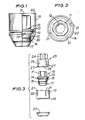
- the vehicle wheel nut according to this invention comprises a main body 10 including a septagonal drive portion 11 and a threaded bore 12 adapted to interengage with a threaded stud projecting from a vehicle wheel hub (not shown).
- the drive portion 11 adjoins a flange 13, itself adjoining a cylindrical portion 14.
- Adjacent the cylindrical portion 14 are two further cylindrical portions 15 and 16, each of a lesser diameter than the preceding portion, the main body 10 having at its end opposed to the drive portion 11 a conical portion 17, adapted for interengagement with a conical recess in a wheel, around the stud-hole therein.
- a sleeve 18 Rotatably mounted on the main body 10 is a sleeve 18, generally of cylindrical shape but having an inturned lip 19 defining a circular opening adapted to be a free running fit on the cylindrical portion 14, the flange 13 serving to locate the sleeve 18 to surround with clearance the drive portion 11.
- the sleeve 18 is retained in position by means of a conical washer 20, press- fitted on to cylindrical portions 15 and 16 of the main body 10, the conical washer 20 having an external conical face which is substantially aligned with the conical face of conical portion 17 of the main body 10, when the conical washer has been pressed fully home as illustrated in Figure 1, also for engagement with a conical recess in a wheel.
- the sleeve 18 has three inwardly directed projections 21, each of these being defined by the material of the sleeve side wall being deformed inwardly.
- the positions of the projections around the sleeve are coded to have predetermined spacings, and each projection extends from the end face 22 of the sleeve parallel to the sleeve axis towards the lip 19, for approximately one half of the length of the sleeve.
- FIG 3 illustrates a key 23 adapted for use in connection with the wheel nut of Figures 1 and 2.
- This key has a hexagonal portion 24, preferably of the same size as the conventional wheel nuts of a motor vehicle to which the wheel nut of this invention is to be fitted, so that only a single spanner or wheel brace need be employed to release the road wheel.
- the key 23 also has a cylindrical portion 25 within which is formed an axially extending socket 26 of a complementary shape and size to the septagonal drive portion 11 of the main body 10, the diameter of the cylindrical portion 25 being essentially the same as the inner diameter of the sleeve 18.
- Three recesses 27 are formed in the circumferential wall of the cylindrical portion 25, the accurate spacing between the recesses 27 and their axial length corresponding to the spacing and dimensions of the projections 21 of the sleeve 18, so that the key 23 may be received within the sleeve 18, by interengaging the projections 21 with the respective recesses 27.
- the end face 22 of the sleeve 18 projects beyond the end of the drive portion 11 of the nut main body 10, so that the projections 21 must first be engaged with the recesses 27 of the key 23, if the drive portion 11 is to be driven by the key. Then, after engaging the key 23 within the sleeve 18, the key and sleeve 18 must together be turned until the orientation of the socket 26 of the key corresponds to that of the drive portion 11; thereafter, the key may be slid axially so as fully to engage the socket 26 with the drive portion 11, whereafter further rotation of the key will turn the drive portion 11.
- the drive portion 11 cannot be turned other than by a key having a socket suitable to engage and drive the drive portion 11 and also having an outer cylindrical surface 25 provided with suitably-disposed recesses 27 to accommodate the projections 21 of the sleeve 18.
- the accurate spacing of the three projections 21 should be coded, and so different as from one nut to another, though four nuts of one coding may be provided for one vehicle, one such nut for each wheel.
- a key 23 adapted for use with one particular nut will only fit those nuts as have the same coded spacings between the projections on the sleeve 18, and the same shaped drive portion.
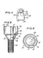
- Figure 3 shows a spring clip 30 which may be used to hold the key 31 to the rod-like shaft 32 of a typical motor vehicle wheel brace.
- Figures 5 and 6 show a security bolt for use with a vehicle having bolts to hold the wheels to the hubs.
- the bolt is generally similar to the nut described with reference to Figures 1 and 2; like parts are given like reference characters and will not be described again.
- the main body 35 has a septagonal drive portion 11, but depending from that drive portion is an externally threaded bolt 36, on which is rotatably mounted a conical washer 37, retained in a groove 38 on the bolt.
- the bolt corresponds to the nut of Figures 1 and 2 and is engageable by a similar key.
- FIGS 7 and 8 show a modified form of key for use with the nut or bolt described above.
- This key 40 has a hexagonal portion 41 contiguous with a cylindrical portion 42 in which there are formed external recesses 43 for interengagement with the projections 21 in sleeve 18, the portion 42 also having a septagonal recess 44 for engagement with the drive portion of a wheel nut or bolt.
- the axis of the hexagonal portion 41 is however offset from the axis of the cylindrical portion 42.
Landscapes
- Engineering & Computer Science (AREA)
- Mechanical Engineering (AREA)
- General Engineering & Computer Science (AREA)
- Dowels (AREA)
Claims (4)
Applications Claiming Priority (2)
| Application Number | Priority Date | Filing Date | Title |
|---|---|---|---|
| GB8614402 | 1986-06-13 | ||
| GB868614402A GB8614402D0 (en) | 1986-06-13 | 1986-06-13 | Security drive assemblies |
Publications (2)
| Publication Number | Publication Date |
|---|---|
| EP0253496A1 EP0253496A1 (de) | 1988-01-20 |
| EP0253496B1 true EP0253496B1 (de) | 1991-02-06 |
Family
ID=10599406
Family Applications (1)
| Application Number | Title | Priority Date | Filing Date |
|---|---|---|---|
| EP87305167A Expired - Lifetime EP0253496B1 (de) | 1986-06-13 | 1987-06-11 | Sicherheitsradmutter oder -bolzen |
Country Status (3)
| Country | Link |
|---|---|
| EP (1) | EP0253496B1 (de) |
| DE (1) | DE3767937D1 (de) |
| GB (1) | GB8614402D0 (de) |
Families Citing this family (12)
| Publication number | Priority date | Publication date | Assignee | Title |
|---|---|---|---|---|
| US5112176A (en) * | 1991-05-09 | 1992-05-12 | Mcgard, Inc. | Shrouded anti-theft locknut |
| DE4215072A1 (de) * | 1992-03-05 | 1993-09-09 | Remotec Dieter Wipperfuerth Gm | Felgenrad, das in felgenpartie und radschuessel bezueglich durchmesser, breite, form und anordnung von unterschiedlichen fahrzeugen passend zuzuordnen ist |
| DE19510547C2 (de) * | 1995-03-23 | 1997-02-20 | Silvretta Sherpas Sportartikel | Diebstahlsicherung |
| WO1997002435A1 (en) * | 1995-07-06 | 1997-01-23 | Thomas Arthur Hamblyn | Theft deterrent device |
| GB9701533D0 (en) | 1997-01-24 | 1997-03-12 | Lees John S | Improved wheel nut assembly |
| GB2352788A (en) | 1999-08-03 | 2001-02-07 | Carflow Products | Anti-theft nut or bolt assembly |
| AU733725B1 (en) * | 2000-04-14 | 2001-05-24 | Okamura Yugen Gaisha | Covering device for nut and covering device for bolt head |
| US6959627B2 (en) * | 2002-08-21 | 2005-11-01 | Jeffrey Doran | Security fastener, system for connection and method therefor |
| US20100000375A1 (en) * | 2008-07-07 | 2010-01-07 | Steinbock Robert C | Tamper resistant jackbolts for a tensioner |
| WO2016017269A1 (ja) * | 2014-07-31 | 2016-02-04 | 日産自動車株式会社 | 車両用ホイールロックアセンブリ |
| US10703136B2 (en) | 2017-03-03 | 2020-07-07 | Mark Phillips | Anti-theft lug nut assembly |
| MX2019005377A (es) | 2019-05-08 | 2019-10-07 | Gildardo Blanco Barrera Gudalupe | Dispositivo de seguridad para medios de rodamiento de vehiculos. |
Citations (1)
| Publication number | Priority date | Publication date | Assignee | Title |
|---|---|---|---|---|
| US4502825A (en) * | 1981-03-30 | 1985-03-05 | Kyodo Electric Co., Ltd. | Multi-headed screw |
Family Cites Families (6)
| Publication number | Priority date | Publication date | Assignee | Title |
|---|---|---|---|---|
| US1447564A (en) * | 1921-11-10 | 1923-03-06 | Olof A Norlund | Lock housing for screws or bolts |
| FR934482A (fr) * | 1946-09-25 | 1948-05-24 | écrou avec cuvette de recouvrement pour la fixation des roues, évitant leur vol | |
| NL6905802A (de) * | 1968-04-16 | 1969-10-20 | ||
| US4205825A (en) * | 1979-05-07 | 1980-06-03 | Stanford George H | Jack for snow plow frames |
| DE3206494A1 (de) * | 1982-02-24 | 1983-09-08 | Rappold, Manfred, Dr., 7117 Bretzfeld | Kopf- und schluesselausbildung fuer eine schraube |
| DD210728A1 (de) * | 1982-10-05 | 1984-06-20 | Schmalkalden Werkzeug | Befestigungselement, insbesondere zur befestigung von raedern an kraftfahrzeugen |
-
1986
- 1986-06-13 GB GB868614402A patent/GB8614402D0/en active Pending
-
1987
- 1987-06-11 DE DE8787305167T patent/DE3767937D1/de not_active Expired - Lifetime
- 1987-06-11 EP EP87305167A patent/EP0253496B1/de not_active Expired - Lifetime
Patent Citations (1)
| Publication number | Priority date | Publication date | Assignee | Title |
|---|---|---|---|---|
| US4502825A (en) * | 1981-03-30 | 1985-03-05 | Kyodo Electric Co., Ltd. | Multi-headed screw |
Also Published As
| Publication number | Publication date |
|---|---|
| DE3767937D1 (de) | 1991-03-14 |
| EP0253496A1 (de) | 1988-01-20 |
| GB8614402D0 (en) | 1986-07-16 |
Similar Documents
| Publication | Publication Date | Title |
|---|---|---|
| US7351020B1 (en) | High security fastener constructions | |
| US4971501A (en) | Self-locking, releasable lock nut | |
| US7445414B1 (en) | High security fastener constructions | |
| US4211128A (en) | Vehicle wheel lug nut apparatus | |
| US5180265A (en) | Self locking nut | |
| US4569259A (en) | Automobile wheel cover locking bolt and wrench combination | |
| US6227782B1 (en) | Self-locking threaded fastener assembly | |
| EP1035336B1 (de) | Befestigungswerkzeug, Befestigungselement und Formwerkzeug | |
| EP0759125B1 (de) | Vorrichtung zum schutz gegen überspannung von bolzen, schrauben und dergleichen | |
| US5544991A (en) | Locking frustrum nut | |
| EP0595306A1 (de) | Kappe für Befestigungsvorrichtungen | |
| WO2005012742A1 (en) | Combination lock washer and spindle bearing assembly | |
| US5302066A (en) | Locking fastener | |
| EP0253496A1 (de) | Sicherheitsradmutter oder -bolzen | |
| CA2318550A1 (en) | Improved wheel nut assembly | |
| US5080544A (en) | Adjustable locknut assembly | |
| US20050008451A1 (en) | Fast locking element | |
| US20240383275A1 (en) | High security fastener with drive coupling key | |
| US4373831A (en) | Key device for locking an element to a shaft | |
| JPS61166705A (ja) | 自動車のホイールのための中央錠止装置 | |
| GB2112488A (en) | Improvements in or relating to threaded fastener and nut assemblies and mounting tools therefor | |
| US20030140664A1 (en) | Anti-theft fastener device | |
| WO2001009527A1 (en) | Anti-theft device | |
| WO2004001237A1 (en) | Screw-threaded fastening | |
| GB2400061A (en) | A key for rotating a fastener |
Legal Events
| Date | Code | Title | Description |
|---|---|---|---|
| PUAI | Public reference made under article 153(3) epc to a published international application that has entered the european phase |
Free format text: ORIGINAL CODE: 0009012 |
|
| AK | Designated contracting states |
Kind code of ref document: A1 Designated state(s): DE FR GB IT |
|
| 17P | Request for examination filed |
Effective date: 19880919 |
|
| 17Q | First examination report despatched |
Effective date: 19881222 |
|
| GRAA | (expected) grant |
Free format text: ORIGINAL CODE: 0009210 |
|
| AK | Designated contracting states |
Kind code of ref document: B1 Designated state(s): DE FR GB IT |
|
| ITF | It: translation for a ep patent filed | ||
| REF | Corresponds to: |
Ref document number: 3767937 Country of ref document: DE Date of ref document: 19910314 |
|
| ET | Fr: translation filed | ||
| PLBE | No opposition filed within time limit |
Free format text: ORIGINAL CODE: 0009261 |
|
| STAA | Information on the status of an ep patent application or granted ep patent |
Free format text: STATUS: NO OPPOSITION FILED WITHIN TIME LIMIT |
|
| 26N | No opposition filed | ||
| ITPR | It: changes in ownership of a european patent |
Owner name: ASSUNZIONE O VARIAZIONE MANDATO;UFFICIO MARCHI & M |
|
| REG | Reference to a national code |
Ref country code: FR Ref legal event code: TP |
|
| PGFP | Annual fee paid to national office [announced via postgrant information from national office to epo] |
Ref country code: GB Payment date: 20000607 Year of fee payment: 14 |
|
| PGFP | Annual fee paid to national office [announced via postgrant information from national office to epo] |
Ref country code: FR Payment date: 20000612 Year of fee payment: 14 |
|
| PGFP | Annual fee paid to national office [announced via postgrant information from national office to epo] |
Ref country code: DE Payment date: 20000614 Year of fee payment: 14 |
|
| PG25 | Lapsed in a contracting state [announced via postgrant information from national office to epo] |
Ref country code: GB Free format text: LAPSE BECAUSE OF NON-PAYMENT OF DUE FEES Effective date: 20010611 |
|
| GBPC | Gb: european patent ceased through non-payment of renewal fee |
Effective date: 20010611 |
|
| PG25 | Lapsed in a contracting state [announced via postgrant information from national office to epo] |
Ref country code: FR Free format text: LAPSE BECAUSE OF NON-PAYMENT OF DUE FEES Effective date: 20020228 |
|
| PG25 | Lapsed in a contracting state [announced via postgrant information from national office to epo] |
Ref country code: DE Free format text: LAPSE BECAUSE OF NON-PAYMENT OF DUE FEES Effective date: 20020403 |
|
| PG25 | Lapsed in a contracting state [announced via postgrant information from national office to epo] |
Ref country code: IT Free format text: LAPSE BECAUSE OF NON-PAYMENT OF DUE FEES;WARNING: LAPSES OF ITALIAN PATENTS WITH EFFECTIVE DATE BEFORE 2007 MAY HAVE OCCURRED AT ANY TIME BEFORE 2007. THE CORRECT EFFECTIVE DATE MAY BE DIFFERENT FROM THE ONE RECORDED. Effective date: 20050611 |