EP0253670A2 - Kabelsteckverbinder - Google Patents
Kabelsteckverbinder Download PDFInfo
- Publication number
- EP0253670A2 EP0253670A2 EP87306335A EP87306335A EP0253670A2 EP 0253670 A2 EP0253670 A2 EP 0253670A2 EP 87306335 A EP87306335 A EP 87306335A EP 87306335 A EP87306335 A EP 87306335A EP 0253670 A2 EP0253670 A2 EP 0253670A2
- Authority
- EP
- European Patent Office
- Prior art keywords
- cable
- housing
- members
- branch
- core
- Prior art date
- Legal status (The legal status is an assumption and is not a legal conclusion. Google has not performed a legal analysis and makes no representation as to the accuracy of the status listed.)
- Granted
Links
- 238000007789 sealing Methods 0.000 claims abstract description 24
- 230000000717 retained effect Effects 0.000 claims abstract description 5
- 239000004020 conductor Substances 0.000 claims description 41
- 238000000034 method Methods 0.000 claims description 24
- 239000012812 sealant material Substances 0.000 claims description 11
- 230000000694 effects Effects 0.000 claims description 6
- 239000011810 insulating material Substances 0.000 claims description 3
- 238000009413 insulation Methods 0.000 abstract description 19
- 239000000463 material Substances 0.000 description 10
- 239000000499 gel Substances 0.000 description 8
- XLYOFNOQVPJJNP-UHFFFAOYSA-N water Substances O XLYOFNOQVPJJNP-UHFFFAOYSA-N 0.000 description 7
- 239000004033 plastic Substances 0.000 description 5
- 229920003023 plastic Polymers 0.000 description 5
- 229920005989 resin Polymers 0.000 description 5
- 239000011347 resin Substances 0.000 description 5
- 238000010276 construction Methods 0.000 description 4
- 239000002184 metal Substances 0.000 description 4
- 230000006378 damage Effects 0.000 description 2
- 238000010292 electrical insulation Methods 0.000 description 2
- 230000007613 environmental effect Effects 0.000 description 2
- 239000003822 epoxy resin Substances 0.000 description 2
- 239000006260 foam Substances 0.000 description 2
- 238000012986 modification Methods 0.000 description 2
- 230000004048 modification Effects 0.000 description 2
- 229920000647 polyepoxide Polymers 0.000 description 2
- 230000003014 reinforcing effect Effects 0.000 description 2
- 238000007792 addition Methods 0.000 description 1
- 230000006835 compression Effects 0.000 description 1
- 238000007906 compression Methods 0.000 description 1
- 239000011243 crosslinked material Substances 0.000 description 1
- 229920001971 elastomer Polymers 0.000 description 1
- 230000005611 electricity Effects 0.000 description 1
- 239000004519 grease Substances 0.000 description 1
- -1 greases Substances 0.000 description 1
- LNEPOXFFQSENCJ-UHFFFAOYSA-N haloperidol Chemical compound C1CC(O)(C=2C=CC(Cl)=CC=2)CCN1CCCC(=O)C1=CC=C(F)C=C1 LNEPOXFFQSENCJ-UHFFFAOYSA-N 0.000 description 1
- 238000003780 insertion Methods 0.000 description 1
- 230000037431 insertion Effects 0.000 description 1
- 239000013521 mastic Substances 0.000 description 1
- 238000000465 moulding Methods 0.000 description 1
- 229920000728 polyester Polymers 0.000 description 1
- 229920001296 polysiloxane Polymers 0.000 description 1
- 238000004382 potting Methods 0.000 description 1
- 238000002360 preparation method Methods 0.000 description 1
- 239000005060 rubber Substances 0.000 description 1
- 238000000926 separation method Methods 0.000 description 1
- 229920001169 thermoplastic Polymers 0.000 description 1
- 229920001187 thermosetting polymer Polymers 0.000 description 1
- 239000004416 thermosoftening plastic Substances 0.000 description 1
- 231100000331 toxic Toxicity 0.000 description 1
- 230000002588 toxic effect Effects 0.000 description 1
- 238000009423 ventilation Methods 0.000 description 1
Images




Classifications
-
- H—ELECTRICITY
- H01—ELECTRIC ELEMENTS
- H01R—ELECTRICALLY-CONDUCTIVE CONNECTIONS; STRUCTURAL ASSOCIATIONS OF A PLURALITY OF MUTUALLY-INSULATED ELECTRICAL CONNECTING ELEMENTS; COUPLING DEVICES; CURRENT COLLECTORS
- H01R9/00—Structural associations of a plurality of mutually-insulated electrical connecting elements, e.g. terminal strips or terminal blocks; Terminals or binding posts mounted upon a base or in a case; Bases therefor
- H01R9/03—Connectors arranged to contact a plurality of the conductors of a multiconductor cable, e.g. tapping connections
- H01R9/031—Connectors arranged to contact a plurality of the conductors of a multiconductor cable, e.g. tapping connections for multiphase cables, e.g. with contact members penetrating insulation of a plurality of conductors
Definitions
- This invention relates to a connector, and particularly, though not exclusively, to a branch-off connector, for an electric cable, especially a power cable.
- the invention finds application primarily with low voltage cables, that is to say cables operating at voltages less than about lkV, it is also applicable to higher voltage cables.
- a branch cable takes electricity from a main cable to supply equipment on a spur.
- the main cable has its outer jacket and any other common outer components of the cable cut back so as to expose the individual, insulated cores of the cable, defining a branch-off region.
- a branch-off connector is mounted on the exposed cores in the branch-off region and has one set of contacts, which may be screw contacts, for connecting to respective ones of the core conductors of the main cable, and another set of contacts for receiving the core conductors of the branch cable. Electrical connection between the branch cable and the main cable is made. Subsequently, electrical insulation and environmental protection is applied to the branch-off region.
- One known method of insulating and protecting the branch-off region involves the positioning of a two-part rigid plastic box around the region, being sealed at each end on to the cable jacket. Epoxy resin is poured in to fill the box and to exclude air from around the connector and between the cores. The resin is allowed to cool and cure.
- This method has the disadvantages of using poten tially toxic materials, and of having to mix two components together, and then pour them into the box before any appreciable curing takes place.
- Another known method of insulating and protecting a branch-off region is to use a heat-recoverable polymeric insulating wraparound sleeve.
- a heat-recoverable polymeric insulating wraparound sleeve available from Raychem with its rail and channel closure system, is wrapped around the branch-off region and extends at each end over the cable jacket.
- the longitudinal sleeve edges, each having a rail formed therealong, are brought into abutment and the channel member slid over them to secure them together.
- Heat for example from a gas torch, is then applied to the sleeve to cause it to shrink into conformity with the underlying components.
- the sleeve is internally coated so as to provide a seal along its closure region and on to the cable. Power may be restored immediately to the main cable, and the shrinking technique is quick, relatively safe, and involves little skill.
- the joint may be re-entered by cutting away the sleeve, and the required action to the connector or cable carried out. Insulation and protection may be re-applied to the branch-off region using a fresh recoverable sleeve.
- An in-ine joint involves the connection of two cables end-to-end.
- an electrical connector that is arranged to seal a region of a cable at which core conductors of the cable are exposed, and that allows electrical connection to be made to the or each core conductor of the cable subsequent to the sealing of said region, and without interrupting said sealing.
- the connector may also allow connection of one or more further cables to be made to the said cable subsequent to the sealing of said region.
- first and second body members are arranged to form a sealed housing around a region of the cable at which core conductors thereof are exposed, and electrical connection of a further cable is subsequently made to the said cable without interrupting said sealing.
- the invention is particularly, though not exclusively, concerned with the provision of a branch-off connector and branch-off connecting method, thus dealing with a branch-off region of a cable (the main cable) that is partway along its length and at which outer components of the cable (such as outer jacket and insulation) have been removed to expose the individually insulated cores so that they may be correctly identified for subsequent connection.
- the further cable is then the branch cable.
- the branch-off connector may be applied to a single core cable, in which case removal of the cable jacket is not usually required.
- the invention is also applicable to an in-line joint, whereby a sealed connection can be provided at an end of a cable for subsequent connection to an end of another cable.
- a cable may have a region at its end at which the core or cores (usually individually insulated) are exposed, and the connector of the invention may be sealingly connected thereto. Electrical connection to a further cable can then be made either at the same time or subsequently, with the original cable having voltage supplied thereto. It will be appreciated that the further cable may itself have a connector in accordance with the invention mounted at one end, so that the interconnection of the two cables involves only the interconnecting of the two connectors.
- the connector of the present invention when applied to the end of a cable, it can be used in place of a conventional end cap.
- An end cap is a sealing component mounted on an exposed end of the cable, for example being heat shrunk thereon, to provide temporary protection until the circuit of which the cable forms part is completed.
- the end cap however, has to be removed, and thereby destroyed, when electrical connection is required to be made to the cable.
- the connector of the invention when used in this way may also be utilised to provide a supply of power from the cable, for example while the cable is temporarily unconnected at a work site.
- a branch-off region of a cable needs to be sealed against ingress of moisture, so that no electrically conductive path is thereby formed between a live conductor and earth, or, in the case of a multi-conductor cable only, between one live conductor (i.e. phase) of the cable and another.
- moisture may penetrate a damaged outer cable jacket and travel along the cable along a core or between the cores.
- the core insulation is broken, e.g. pierced, at a branch-off region, it is necessary to ensure that insulation is re-applied.
- the sealed housing and of connector of the present invention ensures this.
- the housing of the connector of the present invention is accordingly provided with a quantity of cross-linked insulating material for sealing against ingress of moisture.
- the sealant material used in the present invention is cross-linked so as to enhance its performance at higher temperatures, for example at temperatures of 50°C, up to around 95°C and higher, at which power cables can operate under load.
- a non cross-linked material, such as a grease, would melt and flow away at high temperature, thus negating its sealing.
- the following description will refer mainly to a branch-off joint of a multi-core cable, with the cable (the main cable) extending continuously through the connector housing. It is understood that, with suitable modification where necessary, the invention is also applicable to an in-line joint or end cap, and to connection to a single core cable.
- the connector may comprise first and second body members, one or both of which preferably contains or retains the cross-linked moisture resistant sealant material, that together form a housing that encloses the branch-off region.
- the housing may contain, for example by having moulded therein, a plurality of first conductive members to be associated with respective ones of the cores of a multi-core main cable. It is envisaged, however, that only one first conductive member would be required for a single core main cable.
- the first conductive members are each arranged to provide one, and preferably two, or more, electrical contacts that are accessible from an outer surface of the sealed housing for connection to respective cores of a branch cable.
- a plurality of electrical connection members such as insulation piercing screws for example, are preferably mounted in the housing so as to be accessible from an outer surface thereof.
- the connection members are arranged to contact respective ones of the first conductive members, and to pierce the insulation of respective core conductors of the main cable so as to effect electrical contact therewith.
- the electrical connection members may either be permanently retained within the housing, or may be introduced therein at any time when it is required to energise the branch cable. It will be appreciated that the connection members should be sealingly engaged with the housing, and may, after insertion, be covered by insulating plugs, of the cross-linked, insulation, moisture sealant material for example.
- a third body member may be arranged to be mounted at an end of a branch cable and to have exposed at an outer surface thereof a contact of a respective second electrically conductive member that is arranged to be connected with a respective one of the core conductors of the branch cable.
- the third body member is mountable on the housing such that the contacts of the second conductive members are electrically connectable, for example by bolts, with respective ones of the contacts of the first conductive members, thereby to connect the cores of the main cable with those of the branch cable in a one-to-one relationship (phase-to-phase, and earth-to-earth), as required.
- connection and disconnection of the third body member does not disturb the sealing of the branch-off region, since the mounting of the first and second body members on the main cable is not disturbed.
- the third body member may be mounted on the housing in a plurality of different orientations with respect to the main cable.
- the branch cable may be arranged to extend to one or the other side of the main cable, parallel therewith in one or the other direction, or perpendicularly thereto.
- two or more branch cables may be connected to the main cable independently of each other.
- the connector and method of the invention overcomes the destruction of the sealing that is associated with re-entry using known connectors and methods.
- Other pieces of electrical equipment such as a switch, a fuse, or a surge arrestor for example, may also be connected electrically in series with the branch cable, interposed between it and the main cable, and may be so connected without disturbing the sealing of the branch-off region of the main cable.
- branch cables could be mechnically connected to the main cable at one time, left without power supplied thereto (even though the main cable is live), and electrically connected to the main cable at a later time. All of this can be done using the connector and method of the present invention without disturbing the sealing of the branch-off region.
- sealing is required primarily to prevent ingress of water and water vapour into the housing. Such moisture may have entered the cable away from the branch-off region, through a breach inthe cable jacket for example, and may pass along the inside thereof between the cores. It is essential then to ensure that at the branch-off region, where the core conductor insulation has been interrupted, no moisture can form a conductive path between any of the cores (whether at phase voltage or at earth potential).
- the sealing may also conveniently be required to replace the electrical insulation of the removed cable jacket, in the case of a multi-core cable.
- the sealing may conveniently be achieved by having a quantity of the electrically insulating and water resistant cross-linked sealant material, such as gel for example, in one or both of the first and second body members before they are secured together around the branch-off region to form the housing.
- the quantity of gel, or other sealant material is chosen such that all of the air spaces around the conductor cores and within the body members are filled when the housing is formed.
- the following materials when cross- linked are suitable for providing an electrically insulating and water resistant seal of the branch-off region:gels, greases, mastic, unvulcanised soft rubbers, or a water curable material such as silicone.
- the material is a gel, this is preferably a suitable material as described in Patent Application Publication No. WO 86/0l634, the contents of which are herein incorporated by this reference.
- the or each of the body members may be made, for example by moulding, from rigid plastics insulating material.
- the body members of the branch-off connector of the invention may be formed from rigid thermoplastics or thermosetting materials, epoxy resins, or polyester materials, that are capable of mechanically withstanding the temperatures to which they are subjected during normal and test operation of the cable.
- One or more mechanical reinforcing members may be embedded in or applied to the body members if required so as to withstand the mechanical stresses, particularly under thermal cyling that occurs with operation of power cable.
- Such member or members may be of metal, electrically insulated from the other conductive components of the connector.
- the connector which may be a branch-off connector, comprises: first and second body members arranged to be secured together to form a housing enclosing and sealing a cable at a region at which the or each core conductor of the cable is exposed, for example a branch-off region, the housing comprising a first electrically conductive member, for connection to a further, for example branch cable, that provides at least one electrical contact exposed to an outer surface of the housing, and a first electrical connection member mountable within the housing and operable from outside thereof to effect connection between the first conductive member and a core conductor of said main cable, and electrically insulating, cross-linked sealant material contained within the housing for sealing said region against ingress of moisture.
- the cable connection method which may be a method of forming a branch-off connection, compriivelyses the steps of connecting together first and second body members so as to form a housing sealed around a region of the cable at which the or each core of the cable is exposed, for example a branch-off region, in which the housing contains electrically insulating cross-linked sealant material that seals said region against ingress of moisture, and wherein a first electrically conductive member is mounted in the housing so as to expose at least one electrical contact thereof to an outer surface of the housing for connection to a core conductor of a further, for example branch cable, the method further comprising the step of operating from outside the sealed housing an electrical connection member that is mounted in the housing so as to contact a core conductor of the cable, thereby to effect electrical connection, sealed by said sealant material, between said electrical contact and said core conductor.
- a lkV main power cable 2 has four cores 4, one for each of the three phases of the supply and an earth core.
- Each core 4 comprises a sectored conductor enclosed within an individual, colour-coded layer of insulation.
- the four cores 4 are all enclosed within a further layer of insulation and an outer insulating and abrasive-resistant cable jacket.
- a branch cable 6 that has four cores 8 is to be connected to the main cable 2.
- two electrically insulating, half-shells l2,l4 of plastics material are clamped together around the cable 2 at a branch-off region to form a housing l0 that is sealed on to the cable 2.
- the branch-off region is formed by removing the outer jacket and common insulating layer of the cable 2 for a length that is less than that of the housing l0, so as to expose the cores 4, whose individual insulation is left in position. Such preparation of the cable 2 can be carried out with power still being carried by the cable 2.
- the branch cable 6 is cut back at one end thereof to expose the conductors of the cores 8, and a two-part electrically insulating termination block l6 of plastics material is mounted on that end of the cable 6.
- the block l6 is then mounted on the housing l0 for effecting electrical connection beween the conductors of the cores 8 of the branch cable 6 and respective ones of the conductors of the cores 4 of the main cable 2.
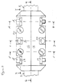
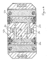
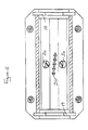
- the half shells l2 and l4 mechanically interlock with each other along their length, are secured together by four bolts l8, and are sealed at each end on to the outer jacket of the continuous cable 2 by foam members l9 ( Figure 5) contained therewithin.
- the housing l0 is thus mechanically retained on the main cable 2 at its branch-off region.
- rigid strips l9 extend between pairs of the bolts l8 over the faces of the half-shells l2,l4.
- the half-shells l2 and l4 are substantially identical, and each is arranged to provide for electrical connection with two of the four cores of the cables 2 and 6.
- each half shell l2,l4 has a further inwardly-projecting rigid divider 22 integrally formed therewith that, on bringing the half shells together, separates the remaining adjacent cable cores.
- the cable cores 4 are located in individual compartments, insulated from each other, and restrained against inward movement, which could otherwise compress and thus reduce in thickness their insulation.
- each half-shell l2,l4 has two connecting members 24 moulded thereinto.
- Each member 24 extends from one side to the other of the housing l0 and exposes an internally threaded contact portion 26 at each of two outer faces thereof. The four exposed contacts at each outer face are located at the corners of a square.
- each connection member 24 extends towards a longitudinally central area of the branch-off region, and has an internally threaded portion 28 directed radially towards a respective one of the compartments containing the cores 4.
- Insulation-piercing electrically conductive screws 30 engage the portions 28, and are accessible from outside the housing l0 ( Figures l,2 and 3) so as to be screwed in through the insulation of the cores 4 to contact respective ones of the core conductors. In this way, electrical connection is established between each core conductor and the two contact portions 26 at the outer surfaces of the housing l0.
- the block l6 has a base 40 and a screw fitted, interlocking cover 42, that provide a water-resistant foam seal 44 around the outer jacket of the entering branch cable 6.
- the common outer jacket of the cable 6 is removed, and the conductors exposed at the ends of the individual insulated cores 8.
- the core conductors are retained within respective moulded-in screw terminals 46 in the base 40 of the block l6.
- Connection members 48 are moulded into the base 40, and extend from respective ones of the terminals 46 to threaded apertures 50 that extend right through the base 40.
- the apertures 50 are located at the corners of a square that is of the same dimension at that of each set of contact portions 26 of the conductive members 24 at opposing outer surfaces of the housing l0.
- the termination block l6 is mounted on the housing l0 ( Figure l and 2) by four conductive bolts 52 that engage the threaded apertures 50 from one side of the block l6, extend therethrough and engage respective ones of the threaded contact portions 26 at an outer surface of the housing l0.
- electrical paths are established between respective ones of the conductors of the cores 4 of the main cable 2 and of the cores 8 of the branch cable 6.
- Each path extends through an insulation piercing screw 30, housing conductive member 24 and contact 26, retaining bolt 52, termination connecting member 48 and screw terminal 46.
- the exposed heads of the bolts 52 and screw terminals 46 may be covered by insulating plugs.
- An electrically-insulating and water-resistant gel which is cross-linked, is arranged to fill any voids within the housing l0 and within the termination block l6, and this is achieved by locating the gel in spaces in each of the four components l2,l4,40,42 such that on bringing the respective components together, the gel is forced into any voids that would otherwise occur, such as for example in the interstices between the cores of the cables 2 and 6, and around the insulation-piercing screws 30.
- the housing l0 may be formed around the branch-off region of the main cable 2 without necessitating cutting the conductors of the main cable and without interrupting the supply of power along the main cable.
- the branch-off connection may thus be left sealed and insulated at this stage of its construction, if required, and completed at a later time.
- the termination block l6 may be fitted to the branch cable 6 without any power being supplied to the branch cable.
- the termination block l6 may be mechanically mounted on the housing l0, by means of the bolts 52, and may still not have power supplied thereto, the branch cable thus being non-activated but sealed and insulated, if required, awaiting energisation at a later time.
- the supply of power to the branch cable does not take place until the screws 30 are screwed in to pierce the insulation of the cores 4 of the main cable 2, and this is arranged so that it may be carried out after the branch-off region has been sealed, and can be carried out after the branch cable has been mechanically secured to the main cable.
- This energising operation can thus be carried out almost as the last stage of forming the branch-off connection, since the screws 30 are accessible from outside the sealed housing l0, even after the branch cable termination block l6 has been mounted thereon. All that remains is to fit insulating plugs over the exposed heads of the screws 30.
- the lock l6 may be mounted on the housing l0 not only in the orientation shown in Figure l, whereby the branch cable 6 extends to the left of the housing l0 and parallel to the main cable 2, but may also be mounted with the branch cable 2 extending in the opposite direction, or extending at right angles, in one direction or the other, to the main cable 2.
- each of these orientations is possible with the termination block l6 mounted on the opposing face of the housing, with the branch cable on the other side of the main cable, electrical connection then being made with the other set of contacts 26 of the connecting members 24 ( Figure 4).
- coding for example colour coding, may be employed to ensure that whatever the chosen orientation of the branch cable, the cores of the branch and main cables will always be correctly matched to each other.
- Figure 9 shows a side elevation, corresponding to the side elevation of Figure 3, of another embodiment of a branch-off connector 60 for use with a four-core cable.
- the connector 60 comprises two identical half-shells that interengage with each other and that are mounted around a main cable 64.
- the shells 62 are made from rigid insulating plastics material and are secured together by two bolts 66 (only on of which is shown) that interengage metal semi-cylindrical inlays 68 in the shells 62.
- the inlays 68 form a metal band around the closed connector 60 that provides mechanical support.
- insulating plugs 70 in each pair of opposing faces of the connector 60 seal the ends of four connecting members (not shown) embedded within the connector, which correspond to the connecting members 24 of the embodiment of the connector described with respect to the earlier Figures.
- Four screws 72 (only two of which are shown) corresponding to the screws 30 of the previous embodiment, are operable from outside the connector and are arranged to pierce the insulation of respective cores of the cable 64.
- the screws 72 are insulated from the metal band 68 through which they pass.
- the internal construction of the connector 60 and in particular the arrangement of conducting components and the gel filling, the operation of the connector, including the interconnection with a branch cable, and other features, correspond to the construction and operation of the connector already described with respect to Figures l to 8.
- the core separators of the connector of the invention may be spring-loaded to enhance their separation of the cores.
- the springs may be put under compression be biassing screws (not shown) operable from outside the connector 60.
- the present invention allows for more than one branch cable to be attached to the main cable at one branch-off region.
- one branch cable attached not only is an opposing set of contacts 26 still available on the other side of the main cable 2, but also, with suitable modification of the retaining bolts 52, one or more, further termination blocks may be mounted on top of the existing one.
- additional branch cable may be added, or existing ones removed, at any time without disturbing the sealing and insulation of the main cable or any existing branch cables, and without interrupting the supply of power to the main cable or to an existing branch cable.
- a switch such as a switch, a fuse, or a surge arrestor may be connected in series with the branch cable, and may be arranged to be interposed between the housing and the termination block.
- the connector may be used as a means of supply of power from the cable to operate other equipment.
- the connector of the invention when the connector of the invention is mounted at the end of a cable, either to act as an end cap, which may be a permanent attachment to the cable, or as part of an in-line joint, it will be desirable to modify the housing, for example to seal one end thereof. It is envisaged that this may most simply be achieved by fitting a disc into the housing formed by the two body members so as to close the opening that in a branch connection would otherwise allow exit of the continuing main cable from the housing.
- the body members may themselves be specifically formed in a different shape for use in such application so as to allow (a) entrance of a single cable, or (b) entrance of two cables with means for electrical interconnection therebetween.
Landscapes
- Cable Accessories (AREA)
- Details Of Connecting Devices For Male And Female Coupling (AREA)
Applications Claiming Priority (2)
| Application Number | Priority Date | Filing Date | Title |
|---|---|---|---|
| GB868617560A GB8617560D0 (en) | 1986-07-18 | 1986-07-18 | Cable connector |
| GB8617560 | 1986-07-18 |
Publications (3)
| Publication Number | Publication Date |
|---|---|
| EP0253670A2 true EP0253670A2 (de) | 1988-01-20 |
| EP0253670A3 EP0253670A3 (en) | 1988-11-02 |
| EP0253670B1 EP0253670B1 (de) | 1994-10-05 |
Family
ID=10601280
Family Applications (1)
| Application Number | Title | Priority Date | Filing Date |
|---|---|---|---|
| EP87306335A Expired - Lifetime EP0253670B1 (de) | 1986-07-18 | 1987-07-17 | Kabelsteckverbinder |
Country Status (4)
| Country | Link |
|---|---|
| EP (1) | EP0253670B1 (de) |
| AT (1) | ATE112654T1 (de) |
| DE (1) | DE3750623T2 (de) |
| GB (1) | GB8617560D0 (de) |
Cited By (9)
| Publication number | Priority date | Publication date | Assignee | Title |
|---|---|---|---|---|
| US4914089A (en) * | 1987-07-06 | 1990-04-03 | Akzo N.V. | Pharmaceutical dosage unit |
| FR2645683A1 (fr) * | 1989-04-10 | 1990-10-12 | Mars Actel | Boite de raccordement pour branchement de cables de derivation sur un cable principal |
| EP0405539A1 (de) * | 1989-06-30 | 1991-01-02 | Cableries De Lens | Wasserdichtes Abzweigungsgehäuse für Niederspannungsleistungskabel |
| EP0492197A3 (en) * | 1990-12-24 | 1993-07-21 | Kabelmetal Electro Gmbh | Junction sleeve for low voltage cable |
| EP0521714A3 (en) * | 1991-07-03 | 1993-08-25 | Raychem Gmbh | Cable connector |
| WO1995006348A1 (en) * | 1993-08-27 | 1995-03-02 | Walter Rose Gmbh & Co. Kg | A cable connector |
| FR2908230A1 (fr) * | 2006-11-07 | 2008-05-09 | Valeo Electronique Sys Liaison | Faisceau de cables surmoule ayant une grande souplesse et procede de fabrication d'un faisceau de ce genre |
| CN115084931A (zh) * | 2022-07-08 | 2022-09-20 | 姚贤木 | 电力电缆集成分支器 |
| CN116805767A (zh) * | 2022-08-31 | 2023-09-26 | 上海兴赣通信设备有限公司 | 一种分支连接器 |
Family Cites Families (3)
| Publication number | Priority date | Publication date | Assignee | Title |
|---|---|---|---|---|
| NL7905180A (nl) * | 1979-07-03 | 1981-01-06 | Electriciteits Mij Ijsselcentr | Kabelmof. |
| DE3330627C2 (de) * | 1983-02-25 | 1990-03-08 | Karl Pfisterer Elektrotechnische Spezialartikel Gmbh & Co Kg, 7000 Stuttgart | Klemme |
| JPH0657773B2 (ja) * | 1984-08-31 | 1994-08-03 | レイケム・コーポレイシヨン | 熱安定性ポリマーゲロイド |
-
1986
- 1986-07-18 GB GB868617560A patent/GB8617560D0/en active Pending
-
1987
- 1987-07-17 EP EP87306335A patent/EP0253670B1/de not_active Expired - Lifetime
- 1987-07-17 AT AT87306335T patent/ATE112654T1/de not_active IP Right Cessation
- 1987-07-17 DE DE3750623T patent/DE3750623T2/de not_active Expired - Fee Related
Cited By (13)
| Publication number | Priority date | Publication date | Assignee | Title |
|---|---|---|---|---|
| US4914089A (en) * | 1987-07-06 | 1990-04-03 | Akzo N.V. | Pharmaceutical dosage unit |
| FR2645683A1 (fr) * | 1989-04-10 | 1990-10-12 | Mars Actel | Boite de raccordement pour branchement de cables de derivation sur un cable principal |
| EP0405539A1 (de) * | 1989-06-30 | 1991-01-02 | Cableries De Lens | Wasserdichtes Abzweigungsgehäuse für Niederspannungsleistungskabel |
| FR2649257A1 (fr) * | 1989-06-30 | 1991-01-04 | Lens Cableries | Boite de derivation etanche pour cable d'energie a basse tension |
| EP0492197A3 (en) * | 1990-12-24 | 1993-07-21 | Kabelmetal Electro Gmbh | Junction sleeve for low voltage cable |
| EP0521714A3 (en) * | 1991-07-03 | 1993-08-25 | Raychem Gmbh | Cable connector |
| WO1995006348A1 (en) * | 1993-08-27 | 1995-03-02 | Walter Rose Gmbh & Co. Kg | A cable connector |
| US5735711A (en) * | 1993-08-27 | 1998-04-07 | Raychem Gmbh | Cable connector |
| AU695717B2 (en) * | 1993-08-27 | 1998-08-20 | Walter Rose Gmbh & Co. Kg. | A cable connector |
| FR2908230A1 (fr) * | 2006-11-07 | 2008-05-09 | Valeo Electronique Sys Liaison | Faisceau de cables surmoule ayant une grande souplesse et procede de fabrication d'un faisceau de ce genre |
| WO2008056061A1 (fr) * | 2006-11-07 | 2008-05-15 | Leoni Wiring Systems France | Faisceau de cables surmoule ayant une grande souplesse et procede de fabrication d'un faisceau de ce genre |
| CN115084931A (zh) * | 2022-07-08 | 2022-09-20 | 姚贤木 | 电力电缆集成分支器 |
| CN116805767A (zh) * | 2022-08-31 | 2023-09-26 | 上海兴赣通信设备有限公司 | 一种分支连接器 |
Also Published As
| Publication number | Publication date |
|---|---|
| DE3750623D1 (de) | 1994-11-10 |
| DE3750623T2 (de) | 1995-05-24 |
| GB8617560D0 (en) | 1986-08-28 |
| EP0253670A3 (en) | 1988-11-02 |
| EP0253670B1 (de) | 1994-10-05 |
| ATE112654T1 (de) | 1994-10-15 |
Similar Documents
| Publication | Publication Date | Title |
|---|---|---|
| US4415217A (en) | Cable joining connector and method | |
| AU682227B2 (en) | Closure for high voltage cable connections | |
| CA1211152A (en) | Apparatus for bonding and protecting electrical cable shields | |
| CA2242379C (en) | Branching connector for an underground cable | |
| EP0253670B1 (de) | Kabelsteckverbinder | |
| EP0087267B1 (de) | Elektrischer Verbinder für Hochspannung und Zusammenbau eines Verbinders | |
| US4710593A (en) | Geophone cable splice and method | |
| US3982319A (en) | Method for connecting a tap assembly to an energized high-voltage cable | |
| US3961127A (en) | Universal power cable joint for use with power cables having various insulations | |
| EP1348248B1 (de) | Verbindungsvorrichtung für mehradriges elektrisches kabel | |
| US6125534A (en) | Method of making a cable joint | |
| US6062917A (en) | Versatile cable connector system for medium voltage underground electrical transmission distribution and the like | |
| US4169966A (en) | Electrical cable joint casing | |
| CA1113558A (en) | Jointing electric cables with a mechanically rigid set compound | |
| EP0521714A2 (de) | Kabelverbinder | |
| AU2002213650B2 (en) | Multi-core electrical cable connection apparatus | |
| US12620729B2 (en) | Reversible splice connector | |
| GB2293497A (en) | Repairing cable installations | |
| AU2002213650A1 (en) | Multi-core electrical cable connection apparatus | |
| GB2277208A (en) | Insulated cable connector | |
| GB2199451A (en) | Electric cable | |
| GB2354374A (en) | Cable joint insert block with insulation displacement contacts | |
| JPH08287999A (ja) | 水中機器のケーブル差込口構造 | |
| CA2625678C (en) | Repositionable insulator | |
| GB2148613A (en) | Electrical heating tapes |
Legal Events
| Date | Code | Title | Description |
|---|---|---|---|
| PUAI | Public reference made under article 153(3) epc to a published international application that has entered the european phase |
Free format text: ORIGINAL CODE: 0009012 |
|
| 17P | Request for examination filed |
Effective date: 19870724 |
|
| AK | Designated contracting states |
Kind code of ref document: A2 Designated state(s): AT BE CH DE FR GB IT LI NL SE |
|
| PUAL | Search report despatched |
Free format text: ORIGINAL CODE: 0009013 |
|
| AK | Designated contracting states |
Kind code of ref document: A3 Designated state(s): AT BE CH DE FR GB IT LI NL SE |
|
| 17Q | First examination report despatched |
Effective date: 19890611 |
|
| GRAA | (expected) grant |
Free format text: ORIGINAL CODE: 0009210 |
|
| AK | Designated contracting states |
Kind code of ref document: B1 Designated state(s): AT BE CH DE FR GB IT LI NL SE |
|
| PG25 | Lapsed in a contracting state [announced via postgrant information from national office to epo] |
Ref country code: IT Free format text: LAPSE BECAUSE OF FAILURE TO SUBMIT A TRANSLATION OF THE DESCRIPTION OR TO PAY THE FEE WITHIN THE PRE;WARNING: LAPSES OF ITALIAN PATENTS WITH EFFECTIVE DATE BEFORE 2007 MAY HAVE OCCURRED AT ANY TIME BEFORE 2007. THE CORRECT EFFECTIVE DATE MAY BE DIFFERENT FROM THE ONE RECORDED.SCRIBED TIME-LIMIT Effective date: 19941005 Ref country code: CH Effective date: 19941005 Ref country code: AT Effective date: 19941005 Ref country code: BE Effective date: 19941005 Ref country code: LI Effective date: 19941005 Ref country code: NL Effective date: 19941005 |
|
| REF | Corresponds to: |
Ref document number: 112654 Country of ref document: AT Date of ref document: 19941015 Kind code of ref document: T |
|
| REF | Corresponds to: |
Ref document number: 3750623 Country of ref document: DE Date of ref document: 19941110 |
|
| ET | Fr: translation filed | ||
| PG25 | Lapsed in a contracting state [announced via postgrant information from national office to epo] |
Ref country code: SE Effective date: 19950105 |
|
| REG | Reference to a national code |
Ref country code: CH Ref legal event code: PL |
|
| NLV1 | Nl: lapsed or annulled due to failure to fulfill the requirements of art. 29p and 29m of the patents act | ||
| PLBE | No opposition filed within time limit |
Free format text: ORIGINAL CODE: 0009261 |
|
| STAA | Information on the status of an ep patent application or granted ep patent |
Free format text: STATUS: NO OPPOSITION FILED WITHIN TIME LIMIT |
|
| 26N | No opposition filed | ||
| REG | Reference to a national code |
Ref country code: GB Ref legal event code: IF02 |
|
| PGFP | Annual fee paid to national office [announced via postgrant information from national office to epo] |
Ref country code: GB Payment date: 20050713 Year of fee payment: 19 |
|
| PGFP | Annual fee paid to national office [announced via postgrant information from national office to epo] |
Ref country code: FR Payment date: 20050718 Year of fee payment: 19 |
|
| PGFP | Annual fee paid to national office [announced via postgrant information from national office to epo] |
Ref country code: DE Payment date: 20050831 Year of fee payment: 19 |
|
| PG25 | Lapsed in a contracting state [announced via postgrant information from national office to epo] |
Ref country code: GB Free format text: LAPSE BECAUSE OF NON-PAYMENT OF DUE FEES Effective date: 20060717 |
|
| PG25 | Lapsed in a contracting state [announced via postgrant information from national office to epo] |
Ref country code: DE Free format text: LAPSE BECAUSE OF NON-PAYMENT OF DUE FEES Effective date: 20070201 |
|
| GBPC | Gb: european patent ceased through non-payment of renewal fee |
Effective date: 20060717 |
|
| REG | Reference to a national code |
Ref country code: FR Ref legal event code: ST Effective date: 20070330 |
|
| PG25 | Lapsed in a contracting state [announced via postgrant information from national office to epo] |
Ref country code: FR Free format text: LAPSE BECAUSE OF NON-PAYMENT OF DUE FEES Effective date: 20060731 |