EP0253718A1 - Gerät zum Abziehen von Schutzüberzügen, wie Handschuhe und Überschuhe in gefährlicher Umgebung - Google Patents
Gerät zum Abziehen von Schutzüberzügen, wie Handschuhe und Überschuhe in gefährlicher Umgebung Download PDFInfo
- Publication number
- EP0253718A1 EP0253718A1 EP87401594A EP87401594A EP0253718A1 EP 0253718 A1 EP0253718 A1 EP 0253718A1 EP 87401594 A EP87401594 A EP 87401594A EP 87401594 A EP87401594 A EP 87401594A EP 0253718 A1 EP0253718 A1 EP 0253718A1
- Authority
- EP
- European Patent Office
- Prior art keywords
- suction
- box
- volume
- machine
- hand
- Prior art date
- Legal status (The legal status is an assumption and is not a legal conclusion. Google has not performed a legal analysis and makes no representation as to the accuracy of the status listed.)
- Granted
Links
- 230000004224 protection Effects 0.000 title claims abstract description 25
- 231100001261 hazardous Toxicity 0.000 title 1
- 210000004247 hand Anatomy 0.000 description 12
- 210000000707 wrist Anatomy 0.000 description 12
- 238000011109 contamination Methods 0.000 description 9
- 230000000694 effects Effects 0.000 description 4
- 239000011324 bead Substances 0.000 description 3
- 230000008901 benefit Effects 0.000 description 2
- 238000005202 decontamination Methods 0.000 description 2
- 230000003588 decontaminative effect Effects 0.000 description 2
- 229920001971 elastomer Polymers 0.000 description 2
- 238000011045 prefiltration Methods 0.000 description 2
- 239000000126 substance Substances 0.000 description 2
- 125000000391 vinyl group Chemical group [H]C([*])=C([H])[H] 0.000 description 2
- 229920002554 vinyl polymer Polymers 0.000 description 2
- 229920000742 Cotton Polymers 0.000 description 1
- 230000009471 action Effects 0.000 description 1
- 210000003414 extremity Anatomy 0.000 description 1
- 239000004744 fabric Substances 0.000 description 1
- 210000003811 finger Anatomy 0.000 description 1
- 230000005484 gravity Effects 0.000 description 1
- 230000036541 health Effects 0.000 description 1
- 229910052500 inorganic mineral Inorganic materials 0.000 description 1
- 238000009434 installation Methods 0.000 description 1
- 239000004816 latex Substances 0.000 description 1
- 229920000126 latex Polymers 0.000 description 1
- 238000004519 manufacturing process Methods 0.000 description 1
- 238000000034 method Methods 0.000 description 1
- 239000011707 mineral Substances 0.000 description 1
- 239000004033 plastic Substances 0.000 description 1
- 229920003023 plastic Polymers 0.000 description 1
- 230000008569 process Effects 0.000 description 1
- 238000007789 sealing Methods 0.000 description 1
- 230000007480 spreading Effects 0.000 description 1
- 210000003813 thumb Anatomy 0.000 description 1
- 231100000331 toxic Toxicity 0.000 description 1
- 230000002588 toxic effect Effects 0.000 description 1
Images


Classifications
-
- A—HUMAN NECESSITIES
- A47—FURNITURE; DOMESTIC ARTICLES OR APPLIANCES; COFFEE MILLS; SPICE MILLS; SUCTION CLEANERS IN GENERAL
- A47G—HOUSEHOLD OR TABLE EQUIPMENT
- A47G25/00—Household implements used in connection with wearing apparel; Dress, hat or umbrella holders
- A47G25/90—Devices for domestic use for assisting in putting-on or pulling-off clothing, e.g. stockings or trousers
- A47G25/904—Devices for domestic use for assisting in putting-on or pulling-off clothing, e.g. stockings or trousers for gloves
-
- A—HUMAN NECESSITIES
- A61—MEDICAL OR VETERINARY SCIENCE; HYGIENE
- A61B—DIAGNOSIS; SURGERY; IDENTIFICATION
- A61B42/00—Surgical gloves; Finger-stalls specially adapted for surgery; Devices for handling or treatment thereof
-
- A—HUMAN NECESSITIES
- A61—MEDICAL OR VETERINARY SCIENCE; HYGIENE
- A61B—DIAGNOSIS; SURGERY; IDENTIFICATION
- A61B42/00—Surgical gloves; Finger-stalls specially adapted for surgery; Devices for handling or treatment thereof
- A61B42/50—Devices for putting-on or removing
-
- B—PERFORMING OPERATIONS; TRANSPORTING
- B25—HAND TOOLS; PORTABLE POWER-DRIVEN TOOLS; MANIPULATORS
- B25J—MANIPULATORS; CHAMBERS PROVIDED WITH MANIPULATION DEVICES
- B25J21/00—Chambers provided with manipulation devices
- B25J21/02—Glove-boxes, i.e. chambers in which manipulations are performed by the human hands in gloves built into the chamber walls; Gloves therefor
-
- G—PHYSICS
- G21—NUCLEAR PHYSICS; NUCLEAR ENGINEERING
- G21F—PROTECTION AGAINST X-RADIATION, GAMMA RADIATION, CORPUSCULAR RADIATION OR PARTICLE BOMBARDMENT; TREATING RADIOACTIVELY CONTAMINATED MATERIAL; DECONTAMINATION ARRANGEMENTS THEREFOR
- G21F7/00—Shielded cells or rooms
- G21F7/04—Shielded glove-boxes
- G21F7/053—Glove mounting means
Definitions
- the present invention relates to a machine for removing protections, such as gloves or overboots and more particularly to a machine for removing protections comprising at least one removal box, a wall, comprising perforations, located in said removal box. and delimiting therein, on the one hand, a receiving volume comprising an entry area opening onto the outside of the removal box to receive a human member coated with a protection and, on the other hand, a volume suction, suction means connected to the suction volume to create a vacuum inside this volume, means for controlling the starting and stopping of the suction means.
- the present invention specifically relates to a machine for removing and putting on protections such as gloves which overcomes the drawbacks of the prior art listed above.
- This machine must be fully automatic. It must make it possible to remove a glove without handling it, in a very short time, of the order of a few seconds, without any risk of contamination for the hands of the operator or another member. It must also make it possible to confine the gloves or other protections removed. In addition, it must adapt to all types of gloves available on the market, whether or not these have a bead at the wrist.
- the machine must allow easy evacuation of this glove. It must also allow easy access to the interior of the dressing box (the removal box) in order to allow its decontamination.
- the invention is characterized in that it includes means making it possible to create a greater depression in the zone of entry of the receiving volume than in the rest of the dressing box.
- these means consist of perforations, located in the entry area and having a relatively larger passage section than in the rest of the perforated wall.
- these means consist of a box located in the inlet zone of said suction box, this box delimiting a separate suction volume and separate from the suction volume of the removal box.
- this preferential suction zone eliminates the need to use a bead or to manually stretch the rim of the glove to fix it on the machine.
- the installation and removal of the glove is therefore fully automatic without any manipulation. They can therefore be carried out in a very short time, of the order of a few seconds.
- manual manipulation is avoided, the risk of contamination for the hands of the operator or another of its members is eliminated.
- the perforated wall consists of two half-shells pivotally mounted relative to one another, the machine further comprising means for controlling the pivoting of at least one of these half-shells so as to leave a passage for the evacuation of the glove.
- the trimmer box opens in two makes it possible to provide a constriction (neck or zone of smaller section) at the wrist. Indeed, it is not necessary for the entry opening of the degening box to have a section large enough to allow the entire hand to pass.
- the geometry of the glove box can be designed to give maximum suction efficiency at the wrist. It is easily understood that the closer the wall is to the wrist, the more efficient the suction will be. This characteristic complements the characteristic stated above according to which the invention comprises means making it possible to create a relatively greater depression at the level of the entry zone of the degening box.
- the glove is easily removed. It can be collected in a bag, for example of plastic, and confined by a known process. This prevents contamination from spreading, which constitutes an additional advantage of the invention.
- FIG. 1 a schematic view of a machine for removing protections according to the present invention.
- This machine the housing 6 of which has been shown diagrammatically by a dashed line, comprises a removal box 2 in which the protection is removed.
- This protection can consist of a glove or an overboot.
- the machine is used to remove gloves from the hands of an operator 4 standing in front of the machine. Box 2 will therefore be called a demolding box in the remainder of the text. Its structure will be explained in more detail later.
- the dressing box 2 is connected by a suction pipe 10 to suction means, shown diagrammatically by the reference 8.
- suction means shown diagrammatically by the reference 8.
- two filters namely a prefilter 12 and an absolute filter 14 are interposed between the removal box 2 and the suction means 8.
- filters are particularly necessary in the nuclear industry to trap the contamination which has been deposited on the outer surface of the glove during handling. In this way, the sucked air can be rejected without inconvenience out of the machine by the exhaust pipe 16. But of course, in other applications the machine can operate without an air filter.
- the machine includes means for controlling the starting and stopping of the suction means 8.
- these means consist of a pedal 18 actuated by the operator 4 himself. When the operator presses on the pedal, he closes a switch 19 which supplies electric power to the suction means 8 which are then started. Conversely, when the operator releases the pressure exerted on the pedal 18, the current is cut and the suction ceases.
- the means for controlling the starting and stopping of the suction means 8 comprise a light source 20 emitting a beam, shown diagrammatically by the arrow 22, directed towards a photoelectric cell 24.
- the beam 22 is interrupted, which causes the starting of the suction means 8 after a certain predetermined delay obtained using a time delay means.
- the protection (s) has been removed from the operator's hand in the manner that will be explained later, it is discharged, preferably by gravity, as shown schematically by the arrow 26, in a receiving tank 28.
- a vinyl bag is tightly connected to the dressing box.
- This bag is sealed by thermal welds made in two different places. A cut is then made between the two welds.
- the contamination remains confined in the bag, without being able to contaminate the interior of the machine.
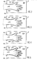
- FIGS. 2 to 5 show four schematic views of a de-gage box 2 of a machine for removing the protections according to the present invention at different stages of operation. These four views illustrate the principle of operation of the machine.
- the dressing box has a perforated wall 50 which divides its internal volume into two zones, namely a zone 64, located outside the perforated wall 50 and a receiving volume 52 whose shape is as close as possible that of a hand 47.
- the suction volume 64 is connected by the pipe 10 to the suction means 8 (see FIG. 1).
- the hand 47 coated with a glove 49 is introduced into the receiving volume delimited by the perforated wall 50.
- the suction volume 64 is at atmospheric pressure. In other words, there is still no depression there so that the glove 49 adheres to the hand over its entire surface.
- the suction means are then started so that a depression appears in the suction volume 64.
- This depression is communicated to the receiving volume 52 through the holes in the perforated wall. Depression larger appears in the wrist area 51.
- the glove 49 peels off first at the wrist and presses against the cylindrical periphery of the inlet 30 of the suction volume 52, which has the effect to create a seal between the inlet of the volume 52 and the surface of the glove 49 and, more generally, the air present in the dressing box is isolated from the atmospheric pressure of the device.
- FIG. 6 shows a perspective view of the upper part of the machine for removing protections according to the invention. It comprises two dressing boxes 2, each comprising an opening 30 opening on the front face of the machine. A suction duct 10 is connected to each of the boxes 2. These two ducts meet in a collecting tube 11 connected to the prefilter 12, then to the filter 14. At the outlet of the filter 14, the collector 11 is connected to a group of suction (not shown).
- the trimmer box 2 consists on the one hand of a housing 32 located at the front of the trimmer box with respect to the front face 31 of the machine, and d on the other hand, from the actual trimmer box, this box containing in hollow an imprint in two parts corresponding to the shape of a hand.
- the function of the housing 32 is to create greater suction at the operator's wrist than in the rest of the hand in order to create an air tightness at the level wrist between the glove and the periphery of the opening of the case 32, as explained above. It comprises a closed chamber 68 connected to a suction pipe 70 which is itself connected to the suction means by means of the suction pipe 10 of the dressing box proper. This achievement improves efficiency. However, one could obviously provide a particular suction pipe for the housing 32.
- the suction chamber 68 of the housing 32 is separate from that of the dressing box proper, which facilitates the appearance of a greater depression. at the wrist than in the rest of the dressing box.
- the perforations 72 made in the entry zone 30 preferably have a larger diameter than the perforations 52a and 52b of the de-dressing box.
- FIGS. 7a and 7b a sectional view of the degening box of the machine for removing the protections of FIG. 6.
- the figure makes it possible to appreciate the two half-shells 40a, 40b articulated on the tube.
- suction 10 which thus acts as a pivot axis.
- the half-shell 40b is connected to the rod of a jack 41 which makes it possible to control the opening and closing of the dressing box so as to leave a passage for evacuation from the glove to the receiving tray 28 (see Figure 1).
- the fixed half-shell 40a is mounted inclined relative to the vertical plane by an angle corresponding to the inclination of the movable half-shell 40b in the maximum open position, so as to leave a larger opening for the evacuation of the glove.
- the suction tube includes lights 43 which connect the suction volumes 64a and 64b of each of the half-shells 40a and 40b. These lights allow the half-shells to be placed under vacuum and are obtained when the dressing boxes are opened.
- An imprint 50a, 50b is provided in each of the planar walls 48a, 48b so as to determine an internal volume 52 corresponding approximately to the shape of a hand.
- the closer the shape of the imprint is to that of a hand the better the suction will be distributed and the removal of the hands facilitated.
- this shape it is not absolutely necessary for this shape to reproduce very faithfully the external contour of a hand so that the suction can peel off the wall of the glove from the operator's skin.
- a simplified form, such as that shown in the figures is sufficient.
- Each of the walls of the imprints 50a, 50b comprises a series of perforations 52a, 52b intended for the passage of air.
- the imprints can be ambidextrous, that is to say identical for the right and left hands. In this case, it suffices that each imprint has two symmetrical locations to receive either the thumb of a right hand or a left hand.
- Automatic means are used to control the opening and closing of the degestion box, as well as the starting and stopping of the sealing means.
- These means can be constituted by the photoelectric cell 20 whose beam is interrupted by the hands 47 of the operator when he introduces them into the dressing boxes 2.
- the interruption of the beam 22 causes the start of the suction cycle with an adjustable delay of one to three seconds.
- the detachment of the glove is carried out, as described above, first at wrist height, then at the level of the palm and the back of the hand and finally at the level of the fingers, until complete release of the hand of the 'operator.
- the operator feeling that his hands are playing freely in the gloves can then remove them and the photoelectric cell causes the electrical circuit of the suction means to be cut.
- the vacuum is canceled and the time-delayed jack 41, the rod of which is fixed to the movable half-shell 40b causes the opening of each of the dressing boxes.
- the gloves then fall into the receiving bin.
- the dressing boxes close under the action of the timed cylinder and the machine is ready for a new suction cycle.
- the dressing boxes are in the closed position during the waiting period.
- the removal of the gloves removed is carried out by suction at the rear end of each box.
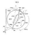
- FIG 8 a sectional view through an alternative embodiment of a dressing box.
- This embodiment consists of two half-shells 140a and 140b articulated by a hinge 142.
- the half-shell 140a is fixed while the half-shell 140b is movable and can come to occupy the position 140'b shown in phantom.
- a return spring 144 permanently biases the half-shell 140b towards its open position, that is to say towards the position 140'b shown in phantom.
- Each half-shell 140a, 140b consists of a semi-cylindrical wall and a flat wall 148 arranged along a diametrical plane of the cylinder.
- An imprint 150a, 150b is provided in each of the planar walls 148a, 148b so as to determine an internal volume 152 corresponding approximately to the shape of a hand.
- Each of the imprints 150a, 150b comprises a series of perforations 152a, 152b intended for the passage of air.
- a suction line 154a, 154b is connected to each of the half-shells 140a, 140b respectively. These pipes are connected to suction means (not shown).
- the half-shell 140b comprises an ear 58 to which is connected one end of a cable 60 passing over a pulley 62.
- the other end of the cable 60 is connected to a control means, for example a pedal which the operator can operate with his foot.
- a control means for example a pedal which the operator can operate with his foot.
- the pedal is not actuated, the half-shell 140b is in the position shown in phantom.
- the receiving volume 152 into which the hands are introduced is open, so as to allow the passage of the glove to a reception (see Figure 1).
- the operator pushes his gloved hands into each of the receiving volumes 152 of the dressing boxes, presses the control pedal which closes the dressing box (position shown in solid lines in FIG. 8) and simultaneously closes a switch which activates routes the suction means with an adjustable delay of one to three seconds.
- the air contained in volumes 64a and 64b is sucked in via lines 154a and 154b so that a vacuum appears in volumes 64a and 64b.
- This depression extends through the perforations to the receiving volume and frees the operator's hands.
- the operator realizing by touch, that his hands are released, can then remove them from the dressing boxes.
Landscapes
- Health & Medical Sciences (AREA)
- Engineering & Computer Science (AREA)
- Surgery (AREA)
- Life Sciences & Earth Sciences (AREA)
- Public Health (AREA)
- Veterinary Medicine (AREA)
- Medical Informatics (AREA)
- Molecular Biology (AREA)
- Animal Behavior & Ethology (AREA)
- General Health & Medical Sciences (AREA)
- Biomedical Technology (AREA)
- Heart & Thoracic Surgery (AREA)
- Robotics (AREA)
- Mechanical Engineering (AREA)
- Physics & Mathematics (AREA)
- General Engineering & Computer Science (AREA)
- High Energy & Nuclear Physics (AREA)
- Gloves (AREA)
- Professional, Industrial, Or Sporting Protective Garments (AREA)
- Manipulator (AREA)
Applications Claiming Priority (2)
| Application Number | Priority Date | Filing Date | Title |
|---|---|---|---|
| FR8610002 | 1986-07-09 | ||
| FR8610002A FR2601492B1 (fr) | 1986-07-09 | 1986-07-09 | Machine a enlever des protections telles que des gants ou surbottes en milieu hostile |
Publications (2)
| Publication Number | Publication Date |
|---|---|
| EP0253718A1 true EP0253718A1 (de) | 1988-01-20 |
| EP0253718B1 EP0253718B1 (de) | 1990-11-07 |
Family
ID=9337258
Family Applications (1)
| Application Number | Title | Priority Date | Filing Date |
|---|---|---|---|
| EP87401594A Expired - Lifetime EP0253718B1 (de) | 1986-07-09 | 1987-07-07 | Gerät zum Abziehen von Schutzüberzügen, wie Handschuhe und Überschuhe in gefährlicher Umgebung |
Country Status (4)
| Country | Link |
|---|---|
| EP (1) | EP0253718B1 (de) |
| JP (1) | JPS6339787A (de) |
| DE (1) | DE3766026D1 (de) |
| FR (1) | FR2601492B1 (de) |
Cited By (3)
| Publication number | Priority date | Publication date | Assignee | Title |
|---|---|---|---|---|
| US20160338518A1 (en) * | 2011-04-29 | 2016-11-24 | David Scott Purcell | Glove Dispensing Apparatus and Glove Cartridge for use Therewith and Glove Dispensing Method |
| CN110755158A (zh) * | 2019-11-11 | 2020-02-07 | 徐州蓝湖信息科技有限公司 | 一种化工安全手套脱除机 |
| IT202000014152A1 (it) * | 2020-06-15 | 2021-12-15 | Gogreeen S A S Di Rossi Maurizio | Apparecchiatura aspiratore per guanti |
Families Citing this family (3)
| Publication number | Priority date | Publication date | Assignee | Title |
|---|---|---|---|---|
| US5323751A (en) * | 1990-07-13 | 1994-06-28 | Toyota Jidosha Kabushiki Kaisha | Device for controlling operation of fuel evaporative purge system of an internal combustion engine |
| US5682862A (en) * | 1993-03-12 | 1997-11-04 | Nissan Motor Co., Ltd. | Control of purge rate of evaporated fuel purging unit for internal combustion engine |
| JP6390383B2 (ja) * | 2014-11-27 | 2018-09-19 | 大日本印刷株式会社 | クリーンルーム内の手袋交換方法、クリーンルーム用手袋交換ボックス及び光学フィルムまたは半導体関連部材の製造方法 |
Citations (3)
| Publication number | Priority date | Publication date | Assignee | Title |
|---|---|---|---|---|
| US1938685A (en) * | 1931-07-16 | 1933-12-12 | Harold E Breuls | Means for applying surgical gloves |
| US1996377A (en) * | 1933-10-25 | 1935-04-02 | Donald T Hinchen | Elastic article applying device |
| US3695493A (en) * | 1970-08-31 | 1972-10-03 | Robert J Karr | Method and apparatus for applying or removing gloves |
-
1986
- 1986-07-09 FR FR8610002A patent/FR2601492B1/fr not_active Expired - Lifetime
-
1987
- 1987-07-07 EP EP87401594A patent/EP0253718B1/de not_active Expired - Lifetime
- 1987-07-07 DE DE8787401594T patent/DE3766026D1/de not_active Expired - Lifetime
- 1987-07-07 JP JP62169595A patent/JPS6339787A/ja active Pending
Patent Citations (3)
| Publication number | Priority date | Publication date | Assignee | Title |
|---|---|---|---|---|
| US1938685A (en) * | 1931-07-16 | 1933-12-12 | Harold E Breuls | Means for applying surgical gloves |
| US1996377A (en) * | 1933-10-25 | 1935-04-02 | Donald T Hinchen | Elastic article applying device |
| US3695493A (en) * | 1970-08-31 | 1972-10-03 | Robert J Karr | Method and apparatus for applying or removing gloves |
Cited By (7)
| Publication number | Priority date | Publication date | Assignee | Title |
|---|---|---|---|---|
| US20160338518A1 (en) * | 2011-04-29 | 2016-11-24 | David Scott Purcell | Glove Dispensing Apparatus and Glove Cartridge for use Therewith and Glove Dispensing Method |
| US20170156530A1 (en) * | 2011-04-29 | 2017-06-08 | David Scott Purcell | Glove Dispensing Apparatus and Glove Cartridge for use Therewith and Glove Dispensing Method |
| US10123644B2 (en) * | 2011-04-29 | 2018-11-13 | David Scott Purcell | Glove dispensing apparatus and glove cartridge for use therewith and glove dispensing method |
| US20190045960A1 (en) * | 2011-04-29 | 2019-02-14 | David Scott Purcell | Glove Dispensing Apparatus and Glove Cartridge for use Therewith and Glove Dispensing Method |
| US10314422B2 (en) * | 2011-04-29 | 2019-06-11 | David Scott Purcell | Glove dispensing apparatus and glove cartridge for use therewith and glove dispensing method |
| CN110755158A (zh) * | 2019-11-11 | 2020-02-07 | 徐州蓝湖信息科技有限公司 | 一种化工安全手套脱除机 |
| IT202000014152A1 (it) * | 2020-06-15 | 2021-12-15 | Gogreeen S A S Di Rossi Maurizio | Apparecchiatura aspiratore per guanti |
Also Published As
| Publication number | Publication date |
|---|---|
| FR2601492A1 (fr) | 1988-01-15 |
| FR2601492B1 (fr) | 1992-01-10 |
| EP0253718B1 (de) | 1990-11-07 |
| DE3766026D1 (de) | 1990-12-13 |
| JPS6339787A (ja) | 1988-02-20 |
Similar Documents
| Publication | Publication Date | Title |
|---|---|---|
| EP0549450B1 (de) | Handschuhhalteeinrichtung für Isolierraum | |
| EP0900100B1 (de) | Pulverinhalator mit drucklufterzeugung | |
| EP2584089B1 (de) | Bügeleisen, das über eine Dampferzeugungskammer verfügt, die mit einem Hohlraum zur Kalkablagerungssammlung enschließlich Entkalkungsöffnung ausgestattet ist | |
| EP0696479B1 (de) | Verpackung für ein Medium, mit einer handbetätigten Pumpe zur Abgabe einzelner Dosen | |
| FR2527124A1 (fr) | Porte-piece a depression | |
| FR2680962A1 (fr) | Extracteur a vide et ensemble de reservoirs pour cet extracteur. | |
| EP1076575A1 (de) | Vorrichtung zum schutz und zur neutralisation einer nadel zum medizinischen gebrauch | |
| FR2486404A1 (fr) | Procede et appareil pour evacuer des fluides de plaies | |
| EP0253718B1 (de) | Gerät zum Abziehen von Schutzüberzügen, wie Handschuhe und Überschuhe in gefährlicher Umgebung | |
| FR2597524A1 (fr) | Module sanitaire a nettoyage automatique | |
| FR2468375A1 (fr) | Seringue perfectionnee dotee de moyens pour isoler l'echantillon de sang apres l'evacuation des agents de contamination | |
| EP1848066A2 (de) | Dichte, gesicherte Stromanschlussvorrichtung | |
| FR2470631A1 (fr) | Dispositif de filtrage pour recuperation de peinture | |
| EP0532405B1 (de) | Vorrichtung zum Ausziehen von verunreinigten Handschuhen | |
| FR2577808A1 (fr) | Dispositif d'aspiration, notamment pour ventouse aspiratrice de venin, comprenant une pompe a vide raccordable a une chambre externe | |
| FR2721188A1 (fr) | Dispositif de fermeture automatique d'un sac à poussière d'aspirateur par clapet. | |
| CH634999A5 (fr) | Dispositif pour l'evacuation des fluides d'une plaie. | |
| FR2728735A1 (fr) | Dispositif pour degainer un cable pollue en surface | |
| FR2763528A1 (fr) | Dispositif d'aspiration de poussieres ou de debris degages par l'attaque d'une surface | |
| WO1997012537A1 (fr) | Aspirateur et sac etanche recuperateur de dechets | |
| FR2639543A1 (fr) | Dispositif de recuperation de residus liquides, a usage unique | |
| EP0016294A1 (de) | Gerät zum Aufbringen eines pastenartigen oder ähnlichen Produktes mittels eines drehbaren Schmierpolsters | |
| FR2631924A1 (fr) | Procede automatique de pose de manchon etirable pour l'etiquetage d'emballages plastiques ou metalliques et dispositif de mise en oeuvre de ce procede | |
| FR2819523A1 (fr) | Boite sterile pour la culture de micro-organismes, ensemble et distributeur de boites | |
| FR2604984A1 (fr) | Dispositif de securite pour appareil a depression |
Legal Events
| Date | Code | Title | Description |
|---|---|---|---|
| PUAI | Public reference made under article 153(3) epc to a published international application that has entered the european phase |
Free format text: ORIGINAL CODE: 0009012 |
|
| AK | Designated contracting states |
Kind code of ref document: A1 Designated state(s): BE DE GB IT |
|
| 17P | Request for examination filed |
Effective date: 19880624 |
|
| 17Q | First examination report despatched |
Effective date: 19890712 |
|
| GRAA | (expected) grant |
Free format text: ORIGINAL CODE: 0009210 |
|
| AK | Designated contracting states |
Kind code of ref document: B1 Designated state(s): BE DE GB IT |
|
| PG25 | Lapsed in a contracting state [announced via postgrant information from national office to epo] |
Ref country code: IT Free format text: LAPSE BECAUSE OF FAILURE TO SUBMIT A TRANSLATION OF THE DESCRIPTION OR TO PAY THE FEE WITHIN THE PRE;WARNING: LAPSES OF ITALIAN PATENTS WITH EFFECTIVE DATE BEFORE 2007 MAY HAVE OCCURRED AT ANY TIME BEFORE 2007. THE CORRECT EFFECTIVE DATE MAY BE DIFFERENT FROM THE ONE RECORDED.SCRIBED TIME-LIMIT Effective date: 19901107 |
|
| REF | Corresponds to: |
Ref document number: 3766026 Country of ref document: DE Date of ref document: 19901213 |
|
| GBT | Gb: translation of ep patent filed (gb section 77(6)(a)/1977) | ||
| PLBE | No opposition filed within time limit |
Free format text: ORIGINAL CODE: 0009261 |
|
| STAA | Information on the status of an ep patent application or granted ep patent |
Free format text: STATUS: NO OPPOSITION FILED WITHIN TIME LIMIT |
|
| 26N | No opposition filed | ||
| PGFP | Annual fee paid to national office [announced via postgrant information from national office to epo] |
Ref country code: DE Payment date: 19920629 Year of fee payment: 6 |
|
| PGFP | Annual fee paid to national office [announced via postgrant information from national office to epo] |
Ref country code: GB Payment date: 19920701 Year of fee payment: 6 |
|
| PGFP | Annual fee paid to national office [announced via postgrant information from national office to epo] |
Ref country code: BE Payment date: 19920702 Year of fee payment: 6 |
|
| PG25 | Lapsed in a contracting state [announced via postgrant information from national office to epo] |
Ref country code: GB Effective date: 19930707 |
|
| PG25 | Lapsed in a contracting state [announced via postgrant information from national office to epo] |
Ref country code: BE Effective date: 19930731 |
|
| BERE | Be: lapsed |
Owner name: COMMISSARIAT A L'ENERGIE ATOMIQUE Effective date: 19930731 |
|
| GBPC | Gb: european patent ceased through non-payment of renewal fee |
Effective date: 19930707 |
|
| PG25 | Lapsed in a contracting state [announced via postgrant information from national office to epo] |
Ref country code: DE Effective date: 19940401 |