EP1848066A2 - Dichte, gesicherte Stromanschlussvorrichtung - Google Patents
Dichte, gesicherte Stromanschlussvorrichtung Download PDFInfo
- Publication number
- EP1848066A2 EP1848066A2 EP07352002A EP07352002A EP1848066A2 EP 1848066 A2 EP1848066 A2 EP 1848066A2 EP 07352002 A EP07352002 A EP 07352002A EP 07352002 A EP07352002 A EP 07352002A EP 1848066 A2 EP1848066 A2 EP 1848066A2
- Authority
- EP
- European Patent Office
- Prior art keywords
- enclosure
- electrical connection
- power supply
- cable
- switch
- Prior art date
- Legal status (The legal status is an assumption and is not a legal conclusion. Google has not performed a legal analysis and makes no representation as to the accuracy of the status listed.)
- Withdrawn
Links
Images



Classifications
-
- H—ELECTRICITY
- H01—ELECTRIC ELEMENTS
- H01R—ELECTRICALLY-CONDUCTIVE CONNECTIONS; STRUCTURAL ASSOCIATIONS OF A PLURALITY OF MUTUALLY-INSULATED ELECTRICAL CONNECTING ELEMENTS; COUPLING DEVICES; CURRENT COLLECTORS
- H01R13/00—Details of coupling devices of the kinds covered by groups H01R12/70 or H01R24/00 - H01R33/00
- H01R13/66—Structural association with built-in electrical component
- H01R13/70—Structural association with built-in electrical component with built-in switch
-
- H—ELECTRICITY
- H01—ELECTRIC ELEMENTS
- H01R—ELECTRICALLY-CONDUCTIVE CONNECTIONS; STRUCTURAL ASSOCIATIONS OF A PLURALITY OF MUTUALLY-INSULATED ELECTRICAL CONNECTING ELEMENTS; COUPLING DEVICES; CURRENT COLLECTORS
- H01R13/00—Details of coupling devices of the kinds covered by groups H01R12/70 or H01R24/00 - H01R33/00
- H01R13/46—Bases; Cases
- H01R13/52—Dustproof, splashproof, drip-proof, waterproof, or flameproof cases
- H01R13/5202—Sealing means between parts of housing or between housing part and a wall, e.g. sealing rings
-
- H—ELECTRICITY
- H01—ELECTRIC ELEMENTS
- H01R—ELECTRICALLY-CONDUCTIVE CONNECTIONS; STRUCTURAL ASSOCIATIONS OF A PLURALITY OF MUTUALLY-INSULATED ELECTRICAL CONNECTING ELEMENTS; COUPLING DEVICES; CURRENT COLLECTORS
- H01R13/00—Details of coupling devices of the kinds covered by groups H01R12/70 or H01R24/00 - H01R33/00
- H01R13/46—Bases; Cases
- H01R13/52—Dustproof, splashproof, drip-proof, waterproof, or flameproof cases
- H01R13/5213—Covers
-
- H—ELECTRICITY
- H01—ELECTRIC ELEMENTS
- H01R—ELECTRICALLY-CONDUCTIVE CONNECTIONS; STRUCTURAL ASSOCIATIONS OF A PLURALITY OF MUTUALLY-INSULATED ELECTRICAL CONNECTING ELEMENTS; COUPLING DEVICES; CURRENT COLLECTORS
- H01R13/00—Details of coupling devices of the kinds covered by groups H01R12/70 or H01R24/00 - H01R33/00
- H01R13/648—Protective earth or shield arrangements on coupling devices, e.g. anti-static shielding
- H01R13/652—Protective earth or shield arrangements on coupling devices, e.g. anti-static shielding with earth pin, blade or socket
-
- H—ELECTRICITY
- H01—ELECTRIC ELEMENTS
- H01R—ELECTRICALLY-CONDUCTIVE CONNECTIONS; STRUCTURAL ASSOCIATIONS OF A PLURALITY OF MUTUALLY-INSULATED ELECTRICAL CONNECTING ELEMENTS; COUPLING DEVICES; CURRENT COLLECTORS
- H01R2103/00—Two poles
-
- H—ELECTRICITY
- H01—ELECTRIC ELEMENTS
- H01R—ELECTRICALLY-CONDUCTIVE CONNECTIONS; STRUCTURAL ASSOCIATIONS OF A PLURALITY OF MUTUALLY-INSULATED ELECTRICAL CONNECTING ELEMENTS; COUPLING DEVICES; CURRENT COLLECTORS
- H01R24/00—Two-part coupling devices, or either of their cooperating parts, characterised by their overall structure
- H01R24/76—Two-part coupling devices, or either of their cooperating parts, characterised by their overall structure with sockets, clips or analogous contacts and secured to apparatus or structure, e.g. to a wall
- H01R24/78—Two-part coupling devices, or either of their cooperating parts, characterised by their overall structure with sockets, clips or analogous contacts and secured to apparatus or structure, e.g. to a wall with additional earth or shield contacts
Definitions
- the one or more switches arranged on the first part of the enclosure inside the free space defined by this enclosure offers a placement of the switch or switches so that their direct controls are inaccessible from the outside of the enclosure. enclosure, but accessible for example in the first position, called electrical connection.
- the outgoing power supply cable is used to power another device according to the invention placed at another place, from a single power supply.
- the device according to the invention further comprises at least one second switch acting on said power supply. delivered by said outgoing power supply cable.
- the second switch makes it possible to cut the outgoing power supply of the device according to the invention while the incoming power supply of this device is for example operational according to the position of the first switch. This feature makes it possible to unbundle the power supply of the devices according to the invention when they have used in a group in the same place or neighboring locations.
- This feature further adds to the safety of the device according to the invention, in that it allows the automation of the systematic shutdown of the power supply for the operation of coupling or separation of the electrical connection means of the electrical appliance on the socket.
- This characteristic further adds to the security in that the surroundings of the enclosure on which the connection to be made is illuminated automatically when necessary, avoiding the operator who must make a connection device, to have actuate an electric switch to illuminate the device according to the invention prior to connection.
- the operator can thus make sure of the cut-off of the power supply before intervening on the electrical connection.
- the device according to the invention further comprises means for wall-tight fixing of said enclosure.
- said at least second watertight passage is disposed between said first and second parts of the enclosure.
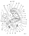
- FIG. 1 represents a partial perspective view of an exemplary embodiment of the sealed electrical connection device according to the invention, in its first electrical connection position.
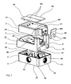
- FIG. 3 represents a partial rear view in perspective of the example of FIG. 1, exploded and comprising the variant embodiments of FIG. 2.
- FIG. 8 represents a diagrammatic view in longitudinal section of an enlarged detail of the device according to FIGS. 1 to 4, 10, relating to an exemplary embodiment of the waterproof wall fixing means of the enclosure.
- FIG. 9 represents a view from above of the example of FIG. 1.
- FIG. 10 represents a sectional view along the line 1-1 of FIG. 9.
- the passage of the opening 34 must have sufficient dimensions to let the electrical connection means 4 to introduce them into the socket 2 which will be disposed opposite this opening 34, as shown in Figures 1 to 3 , without being impeded by a rim 84 advantageously peripheral to the opening 34.
- the casing forming part of the enclosure 5 may adopt any suitable shape, for example a hollow parallelepipedal shape.
- the free space 7 inside the enclosure 5 can accommodate and fix the electrical components (not shown) and / or accessories (not shown) necessary for the operation of the device according to the invention, namely the taking current 2, the connection means 8 of the socket 2 to the incoming power supply cable 9, fuses where appropriate, etc.
- Figure 5 there is shown the inside of the bottom 32 of the housing on which we will return later.
- Each switch has its actuating rod 90.
- the rod 90 advantageously comprises an integral flange 98 which serves as a stop for a spring 99 for returning the rod 90 in the rest position, that is to say in the position of non-contact with the switch, as shown in FIG.
- the flange 98 and the return spring are housed in the tubular guide 93 integral with the cover which advantageously extends from the wall 86 of the cover 14 inside the second subspace of the enclosure 5, in the direction of the corresponding switch.
- the end of the guide 93 may be provided with a nut 100 for retaining the spring 99 inside the guide.
- the nut 100 is pierced at its center to allow the rod 90 to pass through.
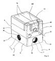
- FIGS. 2 to 4 shows an exemplary embodiment of these specific control means 70; they are constituted for each return means 65 of an actuating plate 101 rotatably mounted at one of its ends on the top of the cover 14, and whose opposite end rests on the sealing cap 94; thus, the operating surface of the return means 65 is increased to facilitate the control of the switches.
- two control plates 101 are arranged parallel to the top of the cover 14 and extend substantially over the entire surface thereof, with a view to respectively controlling the switches 60 and 63 via their means. 65 respectively.
- the device 1 advantageously further comprises light indicator means 68 indicating the operating position of the first 60 and second 63 switches, so as to indicate light outside the enclosure 5 when the power supply of the socket current 2 is established.
- the light indicator means 68 for example the number of two LEDs, one per switch, are respectively connected to the switches 60 and 63 and to the power supply coming from the electric cable 9, so that when the power supply is set to the power outlet 2, the indicator light is on, and when the power supply to the power outlet 2 is cut off, the indicator light 68 is off.
- the device 1 advantageously furthermore comprises means for wall-tight fixing of the enclosure 5, as shown in FIG. 8.
- FIG. 8 represents for this purpose a longitudinal sectional view passing through the bottom angle 32 of the housing of the housing. 5.
- the wall mounting of the device 1 can advantageously be carried out by means of four screws 110 passing through the bottom wall 32 of the housing at the four corners thereof, respectively.
- the device 1 according to the invention may comprise several sockets 2, similar or different, to allow a tight connection of several electrical devices not having all the same electrical connection means. It can also be envisaged that the device 1 according to the invention is fed by several electrical supply cables, involving the realization of several sealed bushings, one by power cable. In the case of the presence of a plurality of sockets, it is preferable for a better sealing of the enclosure, to achieve as many sealed bushings, for example such that the bushing 11 described above, that sockets .
Landscapes
- Connector Housings Or Holding Contact Members (AREA)
Applications Claiming Priority (1)
| Application Number | Priority Date | Filing Date | Title |
|---|---|---|---|
| FR0603438A FR2900282B1 (fr) | 2006-04-19 | 2006-04-19 | Dispositif de branchement electrique etanche securise. |
Publications (2)
| Publication Number | Publication Date |
|---|---|
| EP1848066A2 true EP1848066A2 (de) | 2007-10-24 |
| EP1848066A3 EP1848066A3 (de) | 2010-04-14 |
Family
ID=37499621
Family Applications (1)
| Application Number | Title | Priority Date | Filing Date |
|---|---|---|---|
| EP07352002A Withdrawn EP1848066A3 (de) | 2006-04-19 | 2007-04-19 | Dichte, gesicherte Stromanschlussvorrichtung |
Country Status (2)
| Country | Link |
|---|---|
| EP (1) | EP1848066A3 (de) |
| FR (1) | FR2900282B1 (de) |
Cited By (9)
| Publication number | Priority date | Publication date | Assignee | Title |
|---|---|---|---|---|
| EP2337159A1 (de) * | 2009-12-17 | 2011-06-22 | REV Ritter GmbH | Aufputz-Steckdose und Aufputz-Installationsgeräteserie |
| EP3079209A1 (de) * | 2015-04-09 | 2016-10-12 | TCS TürControlSysteme AG | Befestigungseinrichlung |
| CN106058566A (zh) * | 2016-08-03 | 2016-10-26 | 浙江锦豪电器有限公司 | 一种防水暗藏地插 |
| WO2017121841A1 (en) * | 2016-01-14 | 2017-07-20 | CommScope Connectivity Belgium BVBA | Sealing interface for an enclosure |
| CN111458545A (zh) * | 2020-05-19 | 2020-07-28 | 国网新疆电力有限公司伊犁供电公司 | 便携式电能表通电装置 |
| CN113839319A (zh) * | 2020-06-23 | 2021-12-24 | 易达有限公司 | 包括保护性连接系统的户外供电系统 |
| CN116799550A (zh) * | 2022-03-14 | 2023-09-22 | 英业达科技有限公司 | 组装防水结构的方法 |
| CN119532705A (zh) * | 2025-01-03 | 2025-02-28 | 北京京航安机场工程有限公司 | 一种可快速毗邻安装的机场助航灯箱 |
| AU2024204969A1 (en) * | 2024-07-18 | 2026-02-05 | Yuyao Linsheng Electrical Appliance Co., Ltd | Socket with waterproof structure |
Family Cites Families (2)
| Publication number | Priority date | Publication date | Assignee | Title |
|---|---|---|---|---|
| AT261709B (de) * | 1964-04-07 | 1968-05-10 | Merten Geb | Steckdose mit Schaltwippe |
| FR2868882A1 (fr) * | 2004-04-09 | 2005-10-14 | Clean Lagun Sl | Dispositif de branchement electrique etanche |
-
2006
- 2006-04-19 FR FR0603438A patent/FR2900282B1/fr not_active Expired - Fee Related
-
2007
- 2007-04-19 EP EP07352002A patent/EP1848066A3/de not_active Withdrawn
Cited By (11)
| Publication number | Priority date | Publication date | Assignee | Title |
|---|---|---|---|---|
| EP2337159A1 (de) * | 2009-12-17 | 2011-06-22 | REV Ritter GmbH | Aufputz-Steckdose und Aufputz-Installationsgeräteserie |
| EP3079209A1 (de) * | 2015-04-09 | 2016-10-12 | TCS TürControlSysteme AG | Befestigungseinrichlung |
| WO2017121841A1 (en) * | 2016-01-14 | 2017-07-20 | CommScope Connectivity Belgium BVBA | Sealing interface for an enclosure |
| CN106058566A (zh) * | 2016-08-03 | 2016-10-26 | 浙江锦豪电器有限公司 | 一种防水暗藏地插 |
| CN106058566B (zh) * | 2016-08-03 | 2018-07-20 | 浙江锦豪电器有限公司 | 一种防水暗藏地插 |
| CN111458545A (zh) * | 2020-05-19 | 2020-07-28 | 国网新疆电力有限公司伊犁供电公司 | 便携式电能表通电装置 |
| CN113839319A (zh) * | 2020-06-23 | 2021-12-24 | 易达有限公司 | 包括保护性连接系统的户外供电系统 |
| CN116799550A (zh) * | 2022-03-14 | 2023-09-22 | 英业达科技有限公司 | 组装防水结构的方法 |
| AU2024204969A1 (en) * | 2024-07-18 | 2026-02-05 | Yuyao Linsheng Electrical Appliance Co., Ltd | Socket with waterproof structure |
| AU2024204969B2 (en) * | 2024-07-18 | 2026-04-09 | Yuyao Linsheng Electrical Appliance Co., Ltd | Socket with waterproof structure |
| CN119532705A (zh) * | 2025-01-03 | 2025-02-28 | 北京京航安机场工程有限公司 | 一种可快速毗邻安装的机场助航灯箱 |
Also Published As
| Publication number | Publication date |
|---|---|
| FR2900282A1 (fr) | 2007-10-26 |
| FR2900282B1 (fr) | 2008-07-04 |
| EP1848066A3 (de) | 2010-04-14 |
Similar Documents
| Publication | Publication Date | Title |
|---|---|---|
| EP1848066A2 (de) | Dichte, gesicherte Stromanschlussvorrichtung | |
| EP2805650B1 (de) | Kochtopf, der ein dichtes Gehäuse umfasst | |
| FR2727806A1 (fr) | Dispositif de protection a l'encontre de surtensions transitoires a base de varistances et deconnecteurs thermiques | |
| FR2814139A1 (fr) | Module de commande et d'alimentation electrique integre pour usage a bord d'une bicyclette | |
| FR3005842A1 (fr) | Bouilloire comportant un module de commande etanche | |
| FR2916090A1 (fr) | Dispositif de branchement electrique etanche a configurations multiples | |
| FR2917591A1 (fr) | Appareil de preparation culinaire muni d'un dispositif de securite | |
| FR2979747A1 (fr) | Dispositif d'arret d'urgence adaptable sur un systeme de dialogue homme-machine | |
| EP0653825A1 (de) | Abgedichtete Durchführung mit einer biegsamen Membrane und einem Wegwerfdeckel | |
| EP1976069A1 (de) | Steckdose mit beweglicher Abdeckung, die mit Schnappverschlüssen zum Verriegeln/Entriegeln ausgestattet ist | |
| EP0681307B1 (de) | Sicherheitsvorrichtung für ein elektrisches bewegliches Bauelement und Grill mit einer derartigen Vorrichtung | |
| EP3669714B1 (de) | Dichter elektrisch isolierter wasserkocher, der unter wasser gereinigt werden kann | |
| EP0575214B1 (de) | Umstellbares elektronisches Gerät zur Montage in Wand oder in Gestellrahmen | |
| FR2989527A1 (fr) | Chaussette d'etancheite pour appareillage electrique encastrable | |
| EP3276259B1 (de) | Wasserdichter scheinwerfer und sein herstellungsverfahren | |
| FR2868882A1 (fr) | Dispositif de branchement electrique etanche | |
| EP4092511B1 (de) | Infrarotbeleuchteter touchscreen-rahmen mit uvc-dioden | |
| FR3027166A1 (fr) | Panneau de disjoncteurs | |
| FR2799058A1 (fr) | Adaptateur pour appareillage electrique presentant un sens de montage | |
| FR2677210A1 (fr) | Mode de protection d'une plaque de facade pour appareil electrique, et plaque de facade et appareil electrique correspondants. | |
| FR2640765A1 (fr) | Dispositif de manipulation d'un miroir reflechissant la lumiere | |
| FR2914790A1 (fr) | Prise de courant a double configuration d'alimentation | |
| FR2499713A1 (fr) | Balance electrique | |
| EP0487363A1 (de) | Arbeitstisch mit Kabeldurchführungsabdichtung | |
| EP0508861A1 (de) | Kabeleinführung mit Verankerungsvorrichtung |
Legal Events
| Date | Code | Title | Description |
|---|---|---|---|
| PUAI | Public reference made under article 153(3) epc to a published international application that has entered the european phase |
Free format text: ORIGINAL CODE: 0009012 |
|
| AK | Designated contracting states |
Kind code of ref document: A2 Designated state(s): AT BE BG CH CY CZ DE DK EE ES FI FR GB GR HU IE IS IT LI LT LU LV MC MT NL PL PT RO SE SI SK TR |
|
| AX | Request for extension of the european patent |
Extension state: AL BA HR MK YU |
|
| PUAL | Search report despatched |
Free format text: ORIGINAL CODE: 0009013 |
|
| AK | Designated contracting states |
Kind code of ref document: A3 Designated state(s): AT BE BG CH CY CZ DE DK EE ES FI FR GB GR HU IE IS IT LI LT LU LV MC MT NL PL PT RO SE SI SK TR |
|
| AX | Request for extension of the european patent |
Extension state: AL BA HR MK RS |
|
| AKY | No designation fees paid | ||
| REG | Reference to a national code |
Ref country code: DE Ref legal event code: 8566 |
|
| STAA | Information on the status of an ep patent application or granted ep patent |
Free format text: STATUS: THE APPLICATION IS DEEMED TO BE WITHDRAWN |
|
| 18D | Application deemed to be withdrawn |
Effective date: 20101015 |