EP0253768B1 - Verfahren und Maschine zum Schleifen einer ebenen Fläche - Google Patents
Verfahren und Maschine zum Schleifen einer ebenen Fläche Download PDFInfo
- Publication number
- EP0253768B1 EP0253768B1 EP87810371A EP87810371A EP0253768B1 EP 0253768 B1 EP0253768 B1 EP 0253768B1 EP 87810371 A EP87810371 A EP 87810371A EP 87810371 A EP87810371 A EP 87810371A EP 0253768 B1 EP0253768 B1 EP 0253768B1
- Authority
- EP
- European Patent Office
- Prior art keywords
- grinding
- wheel
- cutter
- rim
- path
- Prior art date
- Legal status (The legal status is an assumption and is not a legal conclusion. Google has not performed a legal analysis and makes no representation as to the accuracy of the status listed.)
- Expired - Lifetime
Links
- 238000000034 method Methods 0.000 title claims abstract description 16
- 238000005096 rolling process Methods 0.000 claims abstract description 10
- 229910003460 diamond Inorganic materials 0.000 claims abstract description 9
- 239000010432 diamond Substances 0.000 claims abstract description 9
- 230000000694 effects Effects 0.000 claims abstract description 9
- 238000006073 displacement reaction Methods 0.000 claims description 10
- 239000004567 concrete Substances 0.000 claims description 7
- 229910001018 Cast iron Inorganic materials 0.000 claims description 4
- 238000005299 abrasion Methods 0.000 claims description 4
- 238000005520 cutting process Methods 0.000 claims description 4
- 239000010959 steel Substances 0.000 claims description 4
- 229910001208 Crucible steel Inorganic materials 0.000 claims description 3
- 230000003042 antagnostic effect Effects 0.000 claims 1
- 230000005540 biological transmission Effects 0.000 claims 1
- 239000011150 reinforced concrete Substances 0.000 claims 1
- 239000000523 sample Substances 0.000 claims 1
- 238000004519 manufacturing process Methods 0.000 abstract 1
- 125000006850 spacer group Chemical group 0.000 description 15
- 238000010276 construction Methods 0.000 description 8
- 239000000463 material Substances 0.000 description 7
- 238000005461 lubrication Methods 0.000 description 4
- 238000009826 distribution Methods 0.000 description 3
- 210000003811 finger Anatomy 0.000 description 3
- 239000011449 brick Substances 0.000 description 2
- 238000012986 modification Methods 0.000 description 2
- 230000004048 modification Effects 0.000 description 2
- 230000002093 peripheral effect Effects 0.000 description 2
- 230000001681 protective effect Effects 0.000 description 2
- 239000002699 waste material Substances 0.000 description 2
- 241000937413 Axia Species 0.000 description 1
- CWYNVVGOOAEACU-UHFFFAOYSA-N Fe2+ Chemical compound [Fe+2] CWYNVVGOOAEACU-UHFFFAOYSA-N 0.000 description 1
- 229910000831 Steel Inorganic materials 0.000 description 1
- 239000003082 abrasive agent Substances 0.000 description 1
- 239000011230 binding agent Substances 0.000 description 1
- 229910010293 ceramic material Inorganic materials 0.000 description 1
- 239000003638 chemical reducing agent Substances 0.000 description 1
- 238000012937 correction Methods 0.000 description 1
- 230000001419 dependent effect Effects 0.000 description 1
- 230000007613 environmental effect Effects 0.000 description 1
- 238000001914 filtration Methods 0.000 description 1
- 238000003780 insertion Methods 0.000 description 1
- 230000037431 insertion Effects 0.000 description 1
- 239000007788 liquid Substances 0.000 description 1
- 230000014759 maintenance of location Effects 0.000 description 1
- 238000005259 measurement Methods 0.000 description 1
- 239000002184 metal Substances 0.000 description 1
- 229910052751 metal Inorganic materials 0.000 description 1
- 239000002245 particle Substances 0.000 description 1
- 239000004033 plastic Substances 0.000 description 1
- 229920003023 plastic Polymers 0.000 description 1
- 230000000284 resting effect Effects 0.000 description 1
- 230000000630 rising effect Effects 0.000 description 1
- 239000004575 stone Substances 0.000 description 1
- 238000012360 testing method Methods 0.000 description 1
- 210000003813 thumb Anatomy 0.000 description 1
- 238000012549 training Methods 0.000 description 1
- 239000002023 wood Substances 0.000 description 1
Images




Classifications
-
- B—PERFORMING OPERATIONS; TRANSPORTING
- B24—GRINDING; POLISHING
- B24B—MACHINES, DEVICES, OR PROCESSES FOR GRINDING OR POLISHING; DRESSING OR CONDITIONING OF ABRADING SURFACES; FEEDING OF GRINDING, POLISHING, OR LAPPING AGENTS
- B24B7/00—Machines or devices designed for grinding plane surfaces on work, including polishing plane glass surfaces; Accessories therefor
- B24B7/06—Machines or devices designed for grinding plane surfaces on work, including polishing plane glass surfaces; Accessories therefor involving conveyor belts, a sequence of travelling work-tables or the like
-
- B—PERFORMING OPERATIONS; TRANSPORTING
- B24—GRINDING; POLISHING
- B24B—MACHINES, DEVICES, OR PROCESSES FOR GRINDING OR POLISHING; DRESSING OR CONDITIONING OF ABRADING SURFACES; FEEDING OF GRINDING, POLISHING, OR LAPPING AGENTS
- B24B53/00—Devices or means for dressing or conditioning abrasive surfaces
- B24B53/02—Devices or means for dressing or conditioning abrasive surfaces of plane surfaces on abrasive tools
Definitions
- the present invention relates to a grinding method and a grinding machine for the grinding of at least one flat surface using at least one rotary grinding wheel.
- the invention relates to the field of planar grinding using an axial grinding wheel.
- the different concepts of this particular field, as well as the concepts of grinding in general, are best defined, at present, in the manual "Begriffe der Schleiftechnik” by Professor Dr. Ing. E. Salgié and Dipl.-Ing. H. Brandin, published by Editions Vulkan in Essen DE.
- the conical wheel can have a straight profile (integral rolling effect) or a slightly bevelled profile to obtain an angle of attack outside or inside the grinding wheel.
- the rolling effect is not integral over the entire generator of the dial, but the difference is negligible.
- the method and the device proposed by the invention allow continuous grinding without requiring any interruption to sharpen the grinding wheel.
- the proposed process is therefore particularly economical for planar grinding in large series of high precision.
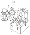
- FIG. 1 shows the general construction of the machine. We will now describe this construction with reference to this fig. 1, the consideration of other figures, in particular of FIG. 2 will facilitate understanding of this construction.
- Machine 1 of fig. 1 includes a base 2 made of pieces of cast iron or steel and concrete. This base is extremely massive; the weight of the whole machine is around seven tonnes. Passages 3 in the base 2 allow the insertion of arms or other lifting means; the machine is transported using special conveyor means.
- the frame also includes a rising part 4, integral with a body with the base 2 and identically constituted by pieces of cast iron or steel and a mass of concrete. At the front a relatively thin wall 5, also made of ferrous material and concrete, rises to the working height of the machine.
- Two tank parts, respectively 6 and 7, are fixed to the left and right of the frame, with the front wall 5 and one face of the upright frame 4, these tank parts form a complete tank, in which the lubrication liquid is collected .
- FIG. 1 shows, for convenience of illustration, the grinding wheel 15, 16 in the raised position.
- FIG. 3 which also corresponds to FIGS. 1 and 2 and where the same reference signs are used, shows the machine in the working position, with a workpiece P fixed on the table 9.
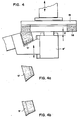
- This fig. 3 makes it possible to understand what is the particular mode of cooperation of the wheel 17 and the abrasive ring 16. This operation will however be explained with the aid of the diagrammatic illustration of FIG. 4. On this one we mainly see the grinding wheel 15, with its abrasive ring 16, and the diamond wheel 17. A workpiece to be ground P rests on the table beam 8.
- the possible range of rotation is given by the length of the arcs 24.
- the rotation of the spacer 23 therefore acts in the manner of a reducer d 'angular deviation, a rotation of a few degrees of the spacer 23 causes a tilting (invisible to the eye) hundred times smaller (a few 0 / oo) of the axis of rotation of the grinding wheel.
- this adjustment, using the spacer 23, is an adjustment made once and for all at construction, to further refine the rigor of transverse perpendicularity.
- Figs. 1, 2, 9 and 10 clearly show how the device works, essential for this kind of grinding, for adjusting perpendicularities.
- the system adopted, with the false parallelism spacer 23, allows two adjustments perpendicular to each other while ensuring a very compact attachment.
- the lever 18 pivots relative to the beam-table 8 and that it comprises two obliquely milled parts for fixing the wheel and its motor.
- a pulley 48 an oblique axis 47 is driven in rotation, in a ball bearing holder block fixed against the oblique wall of the lever 18.
- the active part of the diamond wheel 17 is formed by a part. 49 which surrounds the bearing holder and which can be interchanged if necessary without the entire bearing device being dismantled.
- the motor 19 is similarly mounted against an oblique face of the lever 18 and it carries a pulley 50 connected by a belt to the pulley 48 of the thumb wheel.
- the tank part 7 (fig. 1) is widened on the right side.
Landscapes
- Engineering & Computer Science (AREA)
- Mechanical Engineering (AREA)
- Grinding Of Cylindrical And Plane Surfaces (AREA)
- Polishing Bodies And Polishing Tools (AREA)
Claims (19)
Priority Applications (1)
| Application Number | Priority Date | Filing Date | Title |
|---|---|---|---|
| AT87810371T ATE52955T1 (de) | 1986-07-02 | 1987-06-26 | Verfahren und maschine zum schleifen einer ebenen flaeche. |
Applications Claiming Priority (2)
| Application Number | Priority Date | Filing Date | Title |
|---|---|---|---|
| CH265886 | 1986-07-02 | ||
| CH2658/86 | 1986-07-02 |
Publications (2)
| Publication Number | Publication Date |
|---|---|
| EP0253768A1 EP0253768A1 (de) | 1988-01-20 |
| EP0253768B1 true EP0253768B1 (de) | 1990-05-23 |
Family
ID=4238688
Family Applications (1)
| Application Number | Title | Priority Date | Filing Date |
|---|---|---|---|
| EP87810371A Expired - Lifetime EP0253768B1 (de) | 1986-07-02 | 1987-06-26 | Verfahren und Maschine zum Schleifen einer ebenen Fläche |
Country Status (5)
| Country | Link |
|---|---|
| US (1) | US4760668A (de) |
| EP (1) | EP0253768B1 (de) |
| AT (1) | ATE52955T1 (de) |
| DE (1) | DE3762817D1 (de) |
| ES (1) | ES2015322B3 (de) |
Families Citing this family (21)
| Publication number | Priority date | Publication date | Assignee | Title |
|---|---|---|---|---|
| US5377454A (en) * | 1992-05-01 | 1995-01-03 | The Gleason Works | Method of truing and angling cutter blades by sharpening |
| US5486131A (en) * | 1994-01-04 | 1996-01-23 | Speedfam Corporation | Device for conditioning polishing pads |
| NO179238C (no) * | 1994-06-15 | 1996-09-04 | Norsk Hydro As | Utstyr for tynnsliping av materialpröver |
| DE19625520C1 (de) * | 1996-06-26 | 1997-06-12 | Reishauer Ag | Verfahren und Vorrichtung zum Feinbearbeiten von Stirnzahnrädern |
| EP0858865B1 (de) * | 1997-02-17 | 2002-06-26 | Michael Dr. Ing. Kaiser | Verfahren und Vorrichtung zum Abrichten von Schleifscheiben mit profilierter Arbeitsfläche |
| US5980360A (en) * | 1998-05-06 | 1999-11-09 | Gerber Coburn Optical, Inc. | Method and apparatus for performing work operations on a surface of one or more lenses |
| US6092749A (en) * | 1998-12-03 | 2000-07-25 | Stegmeier; Bill | Dual motor drive system |
| ITBO20000623A1 (it) * | 2000-10-26 | 2002-04-26 | Makor Srl | Macchina levigatrice |
| DE10100870C1 (de) * | 2001-01-11 | 2002-06-20 | Sms Eumuco Gmbh | Verfahren zum Betreiben einer Spitzenlos-Schleifmaschine sowie Spitzenlos-Schleifmaschine zum Durchführen des Verfahrens |
| US7415978B2 (en) * | 2004-10-08 | 2008-08-26 | William Mach | Assembly and a method for cutting or forming an object |
| FR2885834B1 (fr) * | 2005-05-19 | 2008-10-24 | Quadra 1 Soc Par Actions Simpl | Dispositif d'usinage d'elements de construction |
| JP4662083B2 (ja) * | 2008-02-27 | 2011-03-30 | トヨタ自動車株式会社 | 研磨装置 |
| KR20110056976A (ko) * | 2009-11-23 | 2011-05-31 | 삼성전자주식회사 | 휠 팁의 높이를 조절할 수 있는 웨이퍼 연마 장치 |
| US9132521B2 (en) * | 2012-04-11 | 2015-09-15 | Kingsand Machinery Ltd. | Main shaft structure of tool machine |
| JP6803187B2 (ja) * | 2016-10-05 | 2020-12-23 | 株式会社ディスコ | 研削砥石のドレッシング方法 |
| CN108161722B (zh) * | 2018-01-29 | 2023-12-08 | 苏州温特金刚石滚轮有限公司 | 基于金刚石滚轮修整磨床的自动化补料系统 |
| JP7154690B2 (ja) * | 2018-06-22 | 2022-10-18 | 株式会社ディスコ | 研削砥石の目立て方法 |
| TWM597200U (zh) * | 2020-02-18 | 2020-06-21 | 財團法人金屬工業研究發展中心 | 研磨輪量測裝置 |
| JP7718829B2 (ja) * | 2021-03-16 | 2025-08-05 | 株式会社ディスコ | 研削装置及びクリープフィード研削方法 |
| CN114799760A (zh) * | 2022-05-09 | 2022-07-29 | 广东竣昌科技有限公司 | 镶针制造方法 |
| CN116141146A (zh) * | 2023-02-24 | 2023-05-23 | 上海运安制版有限公司 | 一种用于数控车床的顶尖研磨装置 |
Family Cites Families (14)
| Publication number | Priority date | Publication date | Assignee | Title |
|---|---|---|---|---|
| US1831353A (en) * | 1928-04-14 | 1931-11-10 | Diamond Machine Company | Apparatus for grinding |
| US1805955A (en) * | 1929-03-29 | 1931-05-19 | Norton Co | Method of and apparatus for dressing abrasive laps |
| US2222580A (en) * | 1938-07-27 | 1940-11-19 | Julius V Bergfeldt | Grinding machine |
| DE1114109B (de) * | 1957-08-14 | 1961-09-21 | Karl Hack | Einrichtung zum automatischen Abrichten zweier zusammenwirkender Schleifscheiben einer Federendenschleifmaschine |
| US3110988A (en) * | 1960-10-06 | 1963-11-19 | Speedlap Corp | Lapping machine |
| US3353305A (en) * | 1965-01-27 | 1967-11-21 | Bliss E W Co | Tilted spindle grinder |
| GB1339266A (en) * | 1970-08-28 | 1973-11-28 | Williams D G | Grinding or the like machine |
| US3945153A (en) * | 1970-08-28 | 1976-03-23 | C.E.S. (Grinding Machines) Limited | Grinding machine with tilted conveyor and conveyor clearing means |
| US3800636A (en) * | 1972-10-13 | 1974-04-02 | F Zagar | Concrete frame machines |
| JPS5439293A (en) * | 1977-02-15 | 1979-03-26 | Nippon Thompson Co Ltd | Dimensional precision maintaining device in grinding wheel cutting |
| FR2405786A1 (fr) * | 1977-10-17 | 1979-05-11 | Clichy Const Sa | Dispositif de taillage de meules cylindriques |
| US4226055A (en) * | 1979-06-08 | 1980-10-07 | General Electric Company | Dressing and conditioning resin-bonded diamond grinding wheel |
| DE3035635C2 (de) * | 1980-09-20 | 1982-08-12 | Ernst Winter & Sohn ( GmbH & Co.), 2000 Hamburg | Verfahren zum Abrichten von Schleifscheiben mit Diamant oder kubisch kristallinen Bornitrid |
| US4524547A (en) * | 1983-09-06 | 1985-06-25 | Litton Industrial Products, Inc. | Automatic double disc grinder control cycle |
-
1987
- 1987-06-23 US US07/065,477 patent/US4760668A/en not_active Expired - Fee Related
- 1987-06-26 EP EP87810371A patent/EP0253768B1/de not_active Expired - Lifetime
- 1987-06-26 AT AT87810371T patent/ATE52955T1/de not_active IP Right Cessation
- 1987-06-26 DE DE8787810371T patent/DE3762817D1/de not_active Expired - Lifetime
- 1987-06-26 ES ES87810371T patent/ES2015322B3/es not_active Expired - Lifetime
Also Published As
| Publication number | Publication date |
|---|---|
| US4760668A (en) | 1988-08-02 |
| ATE52955T1 (de) | 1990-06-15 |
| ES2015322B3 (es) | 1990-08-16 |
| DE3762817D1 (de) | 1990-06-28 |
| EP0253768A1 (de) | 1988-01-20 |
Similar Documents
| Publication | Publication Date | Title |
|---|---|---|
| EP0253768A1 (de) | Verfahren und Maschine zum Schleifen einer ebenen Fläche | |
| US5836229A (en) | Glass scribing disc | |
| FR2611558A1 (fr) | Dispositif et procede pour affuter les aretes de coupe d'une lame a deplacement alternatif | |
| EP0123891A2 (de) | Verfahren zum Formen einer Sammellinse in einer Platte aus einem transparenten, mineralischen Material | |
| FR2567057A1 (fr) | Appareil de meulage de plaques de verre | |
| FR2571645A1 (fr) | Appareil de meulage de plaques de verre | |
| EP0196941B1 (de) | Vorrichtung zum Schleifen und Polieren der senkrechten Kante eines Steins oder eines vorgefertigten massiven Elementes | |
| BE1017060A3 (de) | ||
| FR2677912A1 (fr) | Dispositif et procede pour arrondir les aretes de disques semiconducteurs. | |
| WO2009007572A1 (fr) | Dispositif rotatif de transfert et d'indexation d'objets metalliques, comportant des moyens d'entrainement sans contact | |
| EP0224419A1 (de) | Vorrichtung und Verfahren zum Bearbeiten oder Messen vor Ort eines sich drehenden Werkstücks | |
| EP1120183A2 (de) | Zwischenplatte zum Einsetzen in einem Schneidschlitz | |
| EP0035939B1 (de) | Mit einem drehenden Werkzeug versehene Maschine für Reproduktions- oder Polierarbeiten | |
| FR2630035A1 (fr) | Machine pour debiter, polir ou fraiser des elements a faces spheriques en pierre | |
| FR2584970A1 (fr) | Dispositif de coupe pour machines de formage d'articles enroules | |
| EP0506533A1 (de) | Sägegerät | |
| BE430747A (de) | ||
| EP0560888B1 (de) | Vorrichtung zum bearbeiten und zur oberflächenbehandlung von elastischen materialien | |
| CN2077777U (zh) | 一种砂轮修整装置 | |
| FR2643583A1 (fr) | Dispositif de coupe de materiaux durs | |
| FR2575955A1 (fr) | Procede et installation pour la rectification et le controle du diametre d'une meule | |
| EP0645189B1 (de) | Verbesserungen an Erdmühlen zur Herstellung von Terrakotta-Produkten | |
| BE838121R (fr) | Machine a chanfreiner les bords de plaques de verre | |
| FR2600375A1 (fr) | Procede d'exploitation de carriere et de debitage direct de pierres ou autres et dispositif pour sa mise en oeuvre | |
| FR2505709A1 (fr) | Procede de formation, sur la surface de pieces, d'un microrelief regulier compose d'evidements separes, tete porte-outil et meule pour la mise en oeuvre dudit procede, et pieces traitees conformement audit procede |
Legal Events
| Date | Code | Title | Description |
|---|---|---|---|
| PUAI | Public reference made under article 153(3) epc to a published international application that has entered the european phase |
Free format text: ORIGINAL CODE: 0009012 |
|
| AK | Designated contracting states |
Kind code of ref document: A1 Designated state(s): AT BE CH DE ES FR GB GR IT LI LU NL SE |
|
| 17P | Request for examination filed |
Effective date: 19880505 |
|
| 17Q | First examination report despatched |
Effective date: 19890811 |
|
| GRAA | (expected) grant |
Free format text: ORIGINAL CODE: 0009210 |
|
| AK | Designated contracting states |
Kind code of ref document: B1 Designated state(s): AT BE CH DE ES FR GB GR IT LI LU NL SE |
|
| PG25 | Lapsed in a contracting state [announced via postgrant information from national office to epo] |
Ref country code: NL Effective date: 19900523 Ref country code: GR Free format text: LAPSE BECAUSE OF FAILURE TO SUBMIT A TRANSLATION OF THE DESCRIPTION OR TO PAY THE FEE WITHIN THE PRESCRIBED TIME-LIMIT Effective date: 19900523 |
|
| REF | Corresponds to: |
Ref document number: 52955 Country of ref document: AT Date of ref document: 19900615 Kind code of ref document: T |
|
| REF | Corresponds to: |
Ref document number: 3762817 Country of ref document: DE Date of ref document: 19900628 |
|
| PG25 | Lapsed in a contracting state [announced via postgrant information from national office to epo] |
Ref country code: LU Free format text: LAPSE BECAUSE OF NON-PAYMENT OF DUE FEES Effective date: 19900630 Ref country code: BE Effective date: 19900630 |
|
| ITF | It: translation for a ep patent filed | ||
| GBT | Gb: translation of ep patent filed (gb section 77(6)(a)/1977) | ||
| NLV1 | Nl: lapsed or annulled due to failure to fulfill the requirements of art. 29p and 29m of the patents act | ||
| BERE | Be: lapsed |
Owner name: SCHLAEFLI ALFRED Effective date: 19900630 |
|
| PLBE | No opposition filed within time limit |
Free format text: ORIGINAL CODE: 0009261 |
|
| STAA | Information on the status of an ep patent application or granted ep patent |
Free format text: STATUS: NO OPPOSITION FILED WITHIN TIME LIMIT |
|
| 26N | No opposition filed | ||
| ITTA | It: last paid annual fee | ||
| PGFP | Annual fee paid to national office [announced via postgrant information from national office to epo] |
Ref country code: ES Payment date: 19941028 Year of fee payment: 8 |
|
| PGFP | Annual fee paid to national office [announced via postgrant information from national office to epo] |
Ref country code: AT Payment date: 19941031 Year of fee payment: 8 |
|
| PGFP | Annual fee paid to national office [announced via postgrant information from national office to epo] |
Ref country code: SE Payment date: 19941102 Year of fee payment: 8 |
|
| PGFP | Annual fee paid to national office [announced via postgrant information from national office to epo] |
Ref country code: FR Payment date: 19941108 Year of fee payment: 8 |
|
| EAL | Se: european patent in force in sweden |
Ref document number: 87810371.2 |
|
| PG25 | Lapsed in a contracting state [announced via postgrant information from national office to epo] |
Ref country code: AT Effective date: 19950626 |
|
| PG25 | Lapsed in a contracting state [announced via postgrant information from national office to epo] |
Ref country code: SE Effective date: 19950627 Ref country code: ES Free format text: LAPSE BECAUSE OF NON-PAYMENT OF DUE FEES Effective date: 19950627 |
|
| PG25 | Lapsed in a contracting state [announced via postgrant information from national office to epo] |
Ref country code: FR Effective date: 19960229 |
|
| EUG | Se: european patent has lapsed |
Ref document number: 87810371.2 |
|
| REG | Reference to a national code |
Ref country code: FR Ref legal event code: ST |
|
| PGFP | Annual fee paid to national office [announced via postgrant information from national office to epo] |
Ref country code: GB Payment date: 19980522 Year of fee payment: 12 |
|
| PGFP | Annual fee paid to national office [announced via postgrant information from national office to epo] |
Ref country code: DE Payment date: 19980528 Year of fee payment: 12 |
|
| PGFP | Annual fee paid to national office [announced via postgrant information from national office to epo] |
Ref country code: CH Payment date: 19980616 Year of fee payment: 12 |
|
| PG25 | Lapsed in a contracting state [announced via postgrant information from national office to epo] |
Ref country code: GB Free format text: LAPSE BECAUSE OF NON-PAYMENT OF DUE FEES Effective date: 19990626 |
|
| PG25 | Lapsed in a contracting state [announced via postgrant information from national office to epo] |
Ref country code: LI Free format text: LAPSE BECAUSE OF NON-PAYMENT OF DUE FEES Effective date: 19990630 Ref country code: CH Free format text: LAPSE BECAUSE OF NON-PAYMENT OF DUE FEES Effective date: 19990630 |
|
| REG | Reference to a national code |
Ref country code: CH Ref legal event code: PL |
|
| GBPC | Gb: european patent ceased through non-payment of renewal fee |
Effective date: 19990626 |
|
| PG25 | Lapsed in a contracting state [announced via postgrant information from national office to epo] |
Ref country code: DE Free format text: LAPSE BECAUSE OF NON-PAYMENT OF DUE FEES Effective date: 20000503 |
|
| REG | Reference to a national code |
Ref country code: ES Ref legal event code: FD2A Effective date: 19960711 |
|
| PG25 | Lapsed in a contracting state [announced via postgrant information from national office to epo] |
Ref country code: IT Free format text: LAPSE BECAUSE OF NON-PAYMENT OF DUE FEES;WARNING: LAPSES OF ITALIAN PATENTS WITH EFFECTIVE DATE BEFORE 2007 MAY HAVE OCCURRED AT ANY TIME BEFORE 2007. THE CORRECT EFFECTIVE DATE MAY BE DIFFERENT FROM THE ONE RECORDED. Effective date: 20050626 |