EP0254043A2 - Einrichtung und Verfahren zum Bearbeiten von Werkstücken - Google Patents
Einrichtung und Verfahren zum Bearbeiten von Werkstücken Download PDFInfo
- Publication number
- EP0254043A2 EP0254043A2 EP87108908A EP87108908A EP0254043A2 EP 0254043 A2 EP0254043 A2 EP 0254043A2 EP 87108908 A EP87108908 A EP 87108908A EP 87108908 A EP87108908 A EP 87108908A EP 0254043 A2 EP0254043 A2 EP 0254043A2
- Authority
- EP
- European Patent Office
- Prior art keywords
- support
- spindle
- workpiece
- gripper
- axis
- Prior art date
- Legal status (The legal status is an assumption and is not a legal conclusion. Google has not performed a legal analysis and makes no representation as to the accuracy of the status listed.)
- Granted
Links
Images



Classifications
-
- B—PERFORMING OPERATIONS; TRANSPORTING
- B23—MACHINE TOOLS; METAL-WORKING NOT OTHERWISE PROVIDED FOR
- B23Q—DETAILS, COMPONENTS, OR ACCESSORIES FOR MACHINE TOOLS, e.g. ARRANGEMENTS FOR COPYING OR CONTROLLING; MACHINE TOOLS IN GENERAL CHARACTERISED BY THE CONSTRUCTION OF PARTICULAR DETAILS OR COMPONENTS; COMBINATIONS OR ASSOCIATIONS OF METAL-WORKING MACHINES, NOT DIRECTED TO A PARTICULAR RESULT
- B23Q7/00—Arrangements for handling work specially combined with or arranged in, or specially adapted for use in connection with, machine tools, e.g. for conveying, loading, positioning, discharging, sorting
- B23Q7/04—Arrangements for handling work specially combined with or arranged in, or specially adapted for use in connection with, machine tools, e.g. for conveying, loading, positioning, discharging, sorting by means of grippers
- B23Q7/048—Multiple gripper units
-
- B—PERFORMING OPERATIONS; TRANSPORTING
- B23—MACHINE TOOLS; METAL-WORKING NOT OTHERWISE PROVIDED FOR
- B23B—TURNING; BORING
- B23B3/00—General-purpose turning-machines or devices, e.g. centre lathes with feed rod and lead screw; Sets of turning-machines
- B23B3/16—Turret lathes for turning individually-chucked workpieces
- B23B3/161—Turret lathes for turning individually-chucked workpieces lathe with one toolslide carrying one turret head
-
- B—PERFORMING OPERATIONS; TRANSPORTING
- B23—MACHINE TOOLS; METAL-WORKING NOT OTHERWISE PROVIDED FOR
- B23Q—DETAILS, COMPONENTS, OR ACCESSORIES FOR MACHINE TOOLS, e.g. ARRANGEMENTS FOR COPYING OR CONTROLLING; MACHINE TOOLS IN GENERAL CHARACTERISED BY THE CONSTRUCTION OF PARTICULAR DETAILS OR COMPONENTS; COMBINATIONS OR ASSOCIATIONS OF METAL-WORKING MACHINES, NOT DIRECTED TO A PARTICULAR RESULT
- B23Q11/00—Accessories fitted to machine tools for keeping tools or parts of the machine in good working condition or for cooling work; Safety devices specially combined with or arranged in, or specially adapted for use in connection with, machine tools
- B23Q11/08—Protective coverings for parts of machine tools; Splash guards
-
- Y—GENERAL TAGGING OF NEW TECHNOLOGICAL DEVELOPMENTS; GENERAL TAGGING OF CROSS-SECTIONAL TECHNOLOGIES SPANNING OVER SEVERAL SECTIONS OF THE IPC; TECHNICAL SUBJECTS COVERED BY FORMER USPC CROSS-REFERENCE ART COLLECTIONS [XRACs] AND DIGESTS
- Y10—TECHNICAL SUBJECTS COVERED BY FORMER USPC
- Y10T—TECHNICAL SUBJECTS COVERED BY FORMER US CLASSIFICATION
- Y10T82/00—Turning
- Y10T82/25—Lathe
- Y10T82/2514—Lathe with work feeder or remover
-
- Y—GENERAL TAGGING OF NEW TECHNOLOGICAL DEVELOPMENTS; GENERAL TAGGING OF CROSS-SECTIONAL TECHNOLOGIES SPANNING OVER SEVERAL SECTIONS OF THE IPC; TECHNICAL SUBJECTS COVERED BY FORMER USPC CROSS-REFERENCE ART COLLECTIONS [XRACs] AND DIGESTS
- Y10—TECHNICAL SUBJECTS COVERED BY FORMER USPC
- Y10T—TECHNICAL SUBJECTS COVERED BY FORMER US CLASSIFICATION
- Y10T82/00—Turning
- Y10T82/25—Lathe
- Y10T82/2514—Lathe with work feeder or remover
- Y10T82/2516—Magazine type
-
- Y—GENERAL TAGGING OF NEW TECHNOLOGICAL DEVELOPMENTS; GENERAL TAGGING OF CROSS-SECTIONAL TECHNOLOGIES SPANNING OVER SEVERAL SECTIONS OF THE IPC; TECHNICAL SUBJECTS COVERED BY FORMER USPC CROSS-REFERENCE ART COLLECTIONS [XRACs] AND DIGESTS
- Y10—TECHNICAL SUBJECTS COVERED BY FORMER USPC
- Y10T—TECHNICAL SUBJECTS COVERED BY FORMER US CLASSIFICATION
- Y10T82/00—Turning
- Y10T82/25—Lathe
- Y10T82/2585—Tool rest
- Y10T82/2587—Turret type holder [e.g., multiple tools, etc.]
Definitions
- the present invention relates to a machine tool having a loader and unloader assembly which removes finished workpieces from a spindle assembly and inserts unfinished workpieces into the spindle assembly.
- An assembly for loading and unloading workpieces includes a pair of arms which are rotated through 120" increments to enable the workpieces to be sequentially loaded into and unloaded from a spindle.
- the loader and unloader assembly is disposed along side of the spindle and requires a substantial amount of space.
- One example of a machine tool having an assembly for loading and unloading workpieces is disclosed in U.S. Patent No. 4,161,849 issued July 24, 1979 and entitled Auxiliary Workpiece-Loading and-Unloading Apparatus.
- Another assembly for transporting finished articles to a machine tool and finished articles from a machine tool includes a pair of arms which are moved through 180° increments to load workpieces into and to remove workpieces from a spindle.
- the loader and unloader assembly is relatively bulky and is mounted to one side of the spindle.
- An example of this type of loader and unloader assembly is described in U.S. Patent No. 4,316,398 issued February 23, 1982 and entitled Loading and/or Unloading Device for Machine Tools, Particularly Automatic Lathes.
- the present invention provides a new and improved method and apparatus for sequentially machining a plurality of workpieces.
- the apparatus includes a machine tool having a spindle with an axis which extends through to a work area. Disposed adjacent to one end of the spindle is a work station at which a tool engages a workpiece. An inner index station, at which a workpiece loader and unloader assembly is indexed, is disposed outwardly of the work station.
- a conveyor assembly is provided to transport unfinished workpieces to a conveyor station and to transport finished workpieces from the conveyor station.
- a shield between the conveyor assembly and the inner index station blocks cuttings removed from a workpiece at the work station.
- an outer index station is provided outwardly of the conveyor station.
- a workpiece loader and unloader assembly is movable along a path which extends parallel to the spindle axis.
- the workpiece loader and unloader assembly has a pair of grippers which are disposed on a rotatable support and are spaced apart by an arcuate distance of less than 90°.
- An opening is provided in the shield to enable the support and grippers to be moved back and forth between various stations.
- one of the grippers engages an unfinished workpiece at an infeed section of the conveyor assembly.
- the grippers and unfinished workpiece are moved through an opening in the shield and the free gripper, that is, the gripper which is not holding the unfinished workpiece, is utilized to remove a finished workpiece from the spindle.
- the grippers After the grippers have been rotated at the inner index station to align the unfinished workpiece with the spindle, the unfinished workpiece is inserted into the spindle.
- the grippers and finished workpiece are then moved back through the opening in the shield and the finished workpiece is transferred to an outfeed section of the conveyor assembly.
- the shield protects the workpiece loader and unloader assembly from chips formed at the work station.
- a compact loader and unloader assembly moves unfinished workpieces from an infeed section of a conveyor assembly to a spindle and transports finished workpieces from the spindle to an outfeed section of the conveyor assembly along a path which extends through an opening in a shield.
- the shield protects the loader and unloader assembly from chips or cutting formed during a machining operation to make the loader and unloader assembly relatively trouble free in operation.
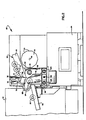
- FIGURE 1 An apparatus 20 for sequentially machining a plurality of workpieces 22 is illustrated in FIGURE 1.
- the apparatus 20 is a machine tool having a base or frame 24 upon which a spindle assembly 26 is mounted.
- the spindle assembly 26 is operable to grip a workpiece 22 and rotate the workpiece about horizontal spindle axis 28.
- a polygonal turret 32 has mounting surfaces 34 upon which cutting tools 35 (FIGURE 4) may be mounted.
- the turret 34 is rotatable about its horizontal central axis 36 by a turret drive assembly 38 (FIGURE 4).
- a second drive assembly 39 is operable to move the turret axially along a path extending parallel to the spindle axis 28.
- the turret 32 is also movable horizontally toward and away from the spindle axis 28 by a third drive assembly 40 (FIGURE 4).
- the horizontal distance between the turret axis 36 and spindle axis 28 will vary during sidewise movement of the turret 32 by the drive assembly 40, the turret axis is always parallel to the spindle axis.
- the machine tool 20 was a WSC-8 Turning Machine which is commercially available from The Warner & Swasey Company of 11000 Cedar Avenue, Cleveland, Ohio 44106.
- This specific machine tool has a General Electric 2000T CNC controller 42 (FIGURE 2) which is programmable to control the operation of the apparatus 20.
- a workpiece loader and unloader assembly 46 is constructed and operated in accordance with the present invention to transfer unfinished workpieces 22 from a conveyor assembly 50 to the spindle assembly 26 and to transfer finished workpieces from the spindle assembly 26 back to the conveyor assembly.
- the loader and unloader assembly 46 is operable to engage an unfinished workpiece 22 on an infeed section 52 of the conveyor assembly 50.
- the loader and unloader assembly 46 transports the unfinished workpiece through an opening 56 in a shield 58 disposed between the conveyor assembly 50 and the spindle assembly 26.
- the workpiece loader and unloader assembly 46 is operable to remove a finished workpiece 22 from the spindle assembly 26 and to insert an unfinished workpiece into the spindle assembly.
- the workpiece loader and unloader assembly 46 then transfers the finished workpiece 22 to an outfeed section 62 of the conveyor assembly 50.
- the infeed and outfeed sections 52 and 62 of the conveyor assembly 50 extend perpendicular to the spindle axis 28 and are constructed to allow the workpieces 22 to move under the influence of gravity to further minimize space requirements.
- the shield 58 protects the loader and unloader assembly 46 and conveyor assembly 50 against a detrimental build up of cuttings during operation of the machine tool 20.
- an outer end face 63 (FIGURE 1) of the turret is adjacent to the shield 58.
- An inner end face 64 of the turret is adjacent to a surface 65 on the base or frame 24 (FIGURE 1) of the machine tool 20 when the turret 32 is fully retracted.
- the conveyor assembly 50 is of the gravity feed type and includes the infeed section 52 (FIGURE 2) and the outfeed section 62 along which workpieces 22 move under the influence of gravity.
- the unfinished workpieces 22 roll down the infeed section 52 to a pick up location 68 (FIGURE 6).
- a first staging pin 70 (Figs 2 and 5) engages a workpiece 22 at the pickup location 68 to stop the workpiece from further movement along the infeed section 52.
- a second staging pin 72 stops movement of a next succeeding workpiece along the infeed section 52 of the conveyor assembly 50.
- the staging pins 70 and 72 are moved between extended positions (shown in FIGURES 2 and 5) and retracted positions by motors or actuators 74 and 76. Operation of the motors 74 and 76 is regulated by the controller 42.
- the infeed conveyor section 52 includes an outer support strip or panel 82 (FIGURE 3) which engages a cylindrical head end portion 84 of the workpiece 22.
- An inner panel or strip 86 extends parallel to the outer panel 82 and engages a conical shank portion 88 of the workpiece.
- An intermediate panel or strip 90 extends parallel to the panels or strips 82 and 86 and cooperates with the panel 82 to trap a circular rim 92 of the workpiece and hold the workpiece against axial movement relative to the conveyor section 52.
- the outfeed conveyor section 62 has the same construction as the infeed section 52.
- the conveyor assembly 50 is designed to receive a workpiece which is a spindle for the wheel of a vehicle, it is contemplated that other conveyor constructions and workpieces could be used if desired.
- the infeed and outfeed sections 52 and 62 of the conveyor assembly 50 extend perpendicular to the spindle axis 28 and are constructed to enable the workpieces 22 to move along the sections under the influence of gravity. Since the infeed and outfeed sections 52 and 62 extend perpendicular to the spindle axis 28, a minimum of space along the spindle axis is required for the conveyor assembly 50. In addition, since the conveyor assembly 50 is constructed to allow the workpieces 22 to move under the influence of gravity, the necessity of having a driven workpiece transfer mechanism is eliminated. Thus, the workpieces 22 roll down the infeed section 52 of the conveyor assembly 50 to the pickup location 68 which is directly above the path along which the loader and unloader assembly 46 moves parallel to the spindle axis 28. The outfeed section 62 of the conveyor assembly 50 slopes downwardly from a drop off location 96 (FIGURE 5) which is disposed at a lower level and is spaced from the pickup location 68 (FIGURE 6).
- the loader assembly 46 includes a carriage 102 (FIGURE 1) which is movable along ways 104 extending parallel to the spindle axis 28.
- a motor 106 is operable to rotate a drive screw 108 (FIGURE 4) which is disposed between and extends parallel to the ways 104.
- An encoder is connected with the motor 106 and drive screw 108 to provide an output to the controller 42 indicative of the position of the carriage 102 along the ways 104.
- the loader and unloader assembly includes a drive assembly 112 which is mounted on the carriage 102.
- the drive assembly 112 is operable to rotate a support member 114 about an axis 126 (FIGURE 4) which is parallel to and offset to one side of the spindle axis 28.
- the drive assembly 112 includes a motor which is connected with the support arm 114 through a gear train and an encoder which provides an output to the controller 42 indicative of the position of the support arm 114 relative to the carriage 102.
- the support member 114 has a generally V-shaped configuration (FIGURE 5).
- a pair of grippers 116 and 118 are mounted on outer end portions of the arms of the support member 114.
- the grippers 116 and 118 are of a known construction and are operated between open and closed conditions by the controller 42.
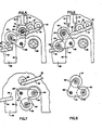
- the grippers 116 and 118 have central axes 120 and 122 which are spaced apart by an arcuate distance of 65° (FIGURE 7) about the axis 126 around which the support arm 114 is rotated by the drive assembly 112.
- the central axes 120 and 122 of the grippers 116 and 118 extend parallel to the support axis 126 and spindle axis 28.
- the support member 114 and grippers 116 and 118 are moved between an outer index station 132 (FIGURES 1 and 4) and a conveyor station 134 at which the conveyor assembly 50 is located.
- the drive assembly l12 can be operated to rotate the support arm and grippers in either a clockwise or counterclockwise direction without interference between a workpiece held by the grippers and the conveyor assembly 50.
- the drive assembly 112 can be operated to pivot the support arm 114 between a pickup orientation (FIGURE 5) and a drop off orientation (FIGURE 6).
- the gripper 116 is axially aligned with an unfinished part 22 disposed at the pickup location 68. Therefore, upon movement of the loader assembly 46 from the outer index station 132 to the conveyor station 134 with the support member 114 in the pickup orientation of FIGURE 5, the open gripper 116 engages a workpiece 22 at the pickup location 68. It should be noted that at this time the gripper 118 is spaced from the outfeed section 62 of the conveyor 50.
- a finished workpiece 22 held by the gripper 118 can be transferred to the outfeed section 62 of the conveyor 50 at the drop off location 96.
- the support arm can be rotated to the unloading orientation of FIGURE 7.
- the support arm l14 is in the unloading orientation of FIGURE 7
- the support arm and grippers 116 and 118 are aligned with the opening 56 in the shield 58.
- the central axis 120 of the gripper 118 is aligned with the spindle axis 28.
- the grippers and support arm are moved through the opening 56 in the shield 58 to a work station 138 disposed immediately adjacent to the outer end of the spindle assembly 26 (see FIGURES 1 and 4). As the open gripper 118 approaches the work station 138, the gripper engages a finished workpiece 22 held by the spindle assembly 26.
- the support arm 114 and grippers 116 and 118 are moved outward to the inner index station 142 by operation of the motor 106 and reverse rotation of the drive screw 108.
- the drive assembly l12 is quickly operated to rotate the grippers 116 and 118 to the loading orientation of FIGURE 8 in which the unfinished workpiece 22 in the gripper 116 is aligned with the open chuck into the spindle assembly 26.
- the motor 106 is then operated to move the gripper 116 back to the work station 138 to insert the unfinished workpiece into the spindle assembly 26.
- the loader and unloader assembly 46 is moved inwardly to remove the finished workpiece from the spindle assembly 26.
- the loader and unloader assembly 46 moves to the outer index station 132 (FIGURE 1) with the finished workpiece 22 held by the gripper 118.
- the gripper 116 is empty and open.
- the drive assembly 112 is then operated by the controller 42 to rotate the support 114 to the pickup orientation of FIGURE 5. This moves the central axis 120 of the open gripper 116 into a coaxial relationship with an unfinished workpiece 22 at the pickup location 68.
- the motor 106 is then operated by the controller 42 to move the support 114 and grippers 116 and 118 from the outer index station 132 to the conveyor station 134.
- the gripper 116 engages a workpiece 22 supported on the infeed section 52 of the conveyor assembly 50 at the pickup location 68.
- the controller 42 then closes the gripper 116 to firmly grip the unfinished workpiece 22.
- the controller 42 then operates the motor 74 to retract the staging pin 70. This releases the unfinished workpiece 22 for movement away from the infeed section 52 of the conveyor assembly 50.
- the drive assembly 112 is operated by the controller 42 to rotate the support 114 in a couterclockwise direction through 40° from the pickup orientation of FIGURE 5 to the drop off orientation of FIGURE 6. As this occurs, a previously finished workpiece held by the gripper 118 is moved into engagement with the outfeed section 62 of the conveyor assembly 50. The controller 42 then operates the gripper assembly 118 to an open condition to release the finished workpiece 22 at the drop off location 96 on the outfeed section 62 of the conveyor assembly 50.
- the motor 106 is operated to move the carriage 102 (FIGURE 1) outwardly to the outer index station 132. This moves the gripper 118 out of engagement with the finished workpiece 22 at the conveyor outfeed section 62. The finished workpiece 22 then rolls down the outfeed section 62 of the conveyor assembly 50 away from the work area 66.
- the controller 42 effects operation of the motor 74 to again extend the staging pin 70. Thereafter, the controller effects operation of the motor 76 to retract the staging pin 72. This allows a next succeeding unfinished workpiece 22 to roll down the infeed conveyor section 52 to the pickup location 68. The controller 42 then operates the motor 76 to again extend the staging pin 72.
- the support 114 and grippers 116 and 118 are rotated in a counterclockwise direction from the drop off orientation of FIGURE .6 through 170° to the unloading orientation of FIGURE 7. This moves the central axis 122 of the open gripper 118 into alignment with the central axis 28 of the spindle assembly 26.
- the gripper 116 is maintained closed holding an unfinished workpiece 22.
- the support 114 remains at the outer index station 132 until the machining of a workpiece 22 held by the spindle assembly 26 is almost completed. At this time, the support 114 may move inward to an intermediate position in which the support is disposed just slightly inwardly of the shield 58 to reduce the distance which to the support has to move to the work station 138. However, it is contemplated that it may be preferred to maintain the support 114 at the outer index station 132 so that the workpiece loader and unloader assembly 46 is spaced from cuttings or chips being formed at the work station 138 by tools on the turret 32 engaging a workpiece 22 as it is rotated by the spindle assembly 26.
- the grippers 116 and 118 and support 114 are aligned with the opening 56 in the shield 58. If desired, the grippers 116 and 118 and the other components of the loader and unloader assembly 46 may be further protected from chips by maintaining the support 114 and grippers 116 and 118 in the pickup orientation of FIGURE 5 until immediately before completion of the machining operation on the workpiece 22. During the final stages of the machining operation, the support 114 may be moved from the pickup orientation of FIGURE 5 to the unloading orientation of FIGURE 7.
- the motor 106 is operated to move the support 114 and grippers 116 and 118 into the work station 138 with the support 114 in the unloading orientation of FIGURE 7. As this occurs, the open gripper 118 engages the finished workpiece.
- the controller 42 then effects operation of the gripper 118 to a closed condition to firmly hold the finished workpiece.
- the chuck in the spindle assembly 26 is then opened by the controller 42 to release the finished workpiece.
- the motor 106 is operated to move the support 114 and grippers 116 and 118 outwardly from the work station 138 to the inner index station 142.
- the finished workpiece held by the gripper 118 and the unfinished workpiece held by the gripper 116 are clear of the spindle assembly 26.
- the drive assembly 112 is then operated to rotate the support 114 through 65° in a counterclockwise direction from the loading orientation of FIGURE 7 to the unloading orientation of FIGURE 8.
- the support 114 moves through a relatively short arcuate distance, that is, an arcuate distance which is less than 90°, the support can be quickly moved from the unloading orientation of FIGURE 7 to the loading orientation of FIGURE 8. Since a workpiece cannot be machined during this time, it is important to minimize the distance through which the support 114 is moved from the unloading orientation to the loading orientation.
- the central axis 120 of the gripper 116 is aligned with the central axis 28 of the spindle assembly 26.
- the motor 106 is then operated to move the support 114 inwardly from the inner index station 142 to the work station 138. As this occurs, the unfinished workpiece held by the gripper 116 is inserted into the open chuck of the spindle assembly 26.
- the controller 42 then effects operation of the spindle chuck to a closed condition to firmly grip the unfinished workpiece.
- the controller 42 then operates the gripper 116 to an open condition.
- the motor 106 is operated to move the support 114 and grippers 116 and 118 outwardly to the inner index station 142 with the support 114 in the loading orientation of FIGURE 8.
- the support 114 and grippers 116 and 118 have moved outwardly for a distance sufficient to enable the finished workpiece 22 in the gripper 118 to clear the unfinished workpiece in the spindle assembly 26
- the support 114 is rotated through 65° in a clockwise direction from the loading orientation of FIGURE 8 back to the unloading orientation of FIGURE 7.
- the support 114 and grippers 116 and 118 move to the unloading orientation of FIGURE 7, they move back into alignment with the opening 56 in the shield 58.
- the support 114 and grippers 116 and 118 are then moved back to the outer index station 132.
- the controller 42 operates the turret drive assembly 40 to move the turret 32 toward the spindle axis 28. Simultaneously therewith, the controller 42 effects operation of the spindle assembly 26 to rotate the workpiece 22 about the spindle axis 28 so that machining of the workpiece can be started with a minimum of lost time.
- the support 114 and grippers 116 and 118 are moved toward the outer index station 132 with the support in the unloading orientation of FIGURE 7. Since cuttings which tend to accumulate on and interfere with the operation of the grippers 116 and 118 are being formed during the machining operation, it is contemplated that the drive assembly 112 will be operated to rotate the support 114 and grippers 116 and 118 from the unloading orientation of FIGURE 7 in a counterclockwise direction through 150° to the pickup orientation of FIGURE 5.
- the shield 58 is disposed between the grippers and the work station 138 where cuttings are being generated during high speed rotation of the workpiece by the spindle assembly 26.
- the shield 58 has an opening 56 through which some cuttings or chips may pass.
- the volume and type of cuttings are such that the amount which will pass through the opening 56 would not be objectionable.
- FIGURE 9 the opening in the shield is closed during a machining operation. Since the embodiment of the invention shown in FIGURE 9 is generally similar to the embodiment of the invention shown in FIGURES 1-8, similar numerals will be utilized to designate similar components, the suffix letter "a" being added to the numerals of FIGURE 9 to avoid confusion.
- the shield 58a has an opening 56a through which the support 114 and grippers 116 and 118 of the loader and unloader assembly 46 of FIGURES 1-8 may move.
- a door or slide panel 150 is provided to block the opening 56a during a machining operation.
- a pneumatic motor 152 is operated by the controller 42 to raise the door 150 and unblock the opening 56a. With the door 150 raised, the various components of the workpiece loader and unloader assembly can move through the shield 58a.
- the shield is recessed to accomodate a relatively long stroke of the turret. Since the embodiment of the invention illustrated in FIGURE 10 is generally similar to the embodiment of the invention illustrated in FIGURES 1-8, similar numerals will be utilized to designate similar components, the suffix letter 8 b 8 being added to the numerals of FIGURE 10 to avoid confusion.
- the shield 58b is disposed between the conveyor .assembly 50b and the inner index station 142b.
- the shield 58b has a recess 158 into which the turret 32b can move.
- the turret 32b can be moved through a relatively long operating stroke so that the outer end portion of the turret is disposed in the recess 158 beneath the conveyor assembly 50b.
- the shield 58b is provided with an opening, similar to the opening 56 of FIGURES 1-8.
- the apparatus includes a machine tool having a spindle assembly 26 with an axis 28 which extends through a work area 66. Proceeding outwardly from the spindle assembly 26, a work station,138 at which a tool engages a workpiece 22 is disposed adjacent to one end of the spindle assembly. An inner index station 142, at which a workpiece loader and unloader assembly 46 is indexed, is disposed outwardly of the work station 138.
- a conveyor assembly 50 is provided to transport unfinished workpieces 22 to a conveyor station 134 and to transport finished workpieces from the conveyor station.
- an outer index station 132 is provided outwardly of the conveyor station 134.
- the workpiece loader and unloader assembly 46 is movable along a path which extends parallel to the spindle axis 28.
- the workpiece loader and unloader assembly 46 has a pair of grippers 116 and 118 which are disposed on a rotatable support 114 and are spaced apart by an arcuate distance of less than 90°.
- An opening 56 is provided in the shield 58 to enable the support 114 and grippers 116 and 118 to be moved back and forth between various stations 132, 134, 138 and 142.
- the gripper 116 engages an unfinished workpiece 27 at an infeed section 52 of the conveyor assembly 50.
- the grippers 116 and 118 and unfinished workpiece 22 are moved through an opening 56 in the shield 58 and the gripper 118 is utilized to remove a finished workpiece 22 from the spindle assembly 26.
- the unfinished workpiece 22 is inserted into the spindle assembly 26.
- the grippers 116 and 118 and finished workpiece 22 are then moved back through the opening 56 in the shield 58 and the finished workpiece is transferred to the outfeed section 62 of the conveyor assembly 50.
- the shield 58 protects the workpiece loader and unloader assembly 46 from chips formed at the work station 138.
Landscapes
- Engineering & Computer Science (AREA)
- Mechanical Engineering (AREA)
- Feeding Of Workpieces (AREA)
- Turning (AREA)
- Automatic Assembly (AREA)
Applications Claiming Priority (2)
| Application Number | Priority Date | Filing Date | Title |
|---|---|---|---|
| US06/889,987 US4787280A (en) | 1986-07-24 | 1986-07-24 | Apparatus for machining workpieces and method therefor |
| US889987 | 1997-07-10 |
Publications (3)
| Publication Number | Publication Date |
|---|---|
| EP0254043A2 true EP0254043A2 (de) | 1988-01-27 |
| EP0254043A3 EP0254043A3 (en) | 1988-12-21 |
| EP0254043B1 EP0254043B1 (de) | 1992-05-06 |
Family
ID=25396074
Family Applications (1)
| Application Number | Title | Priority Date | Filing Date |
|---|---|---|---|
| EP87108908A Expired - Lifetime EP0254043B1 (de) | 1986-07-24 | 1987-06-22 | Einrichtung und Verfahren zum Bearbeiten von Werkstücken |
Country Status (6)
| Country | Link |
|---|---|
| US (1) | US4787280A (de) |
| EP (1) | EP0254043B1 (de) |
| JP (1) | JPS6334046A (de) |
| CA (1) | CA1266555A (de) |
| DE (1) | DE3778777D1 (de) |
| ES (1) | ES2031851T3 (de) |
Cited By (2)
| Publication number | Priority date | Publication date | Assignee | Title |
|---|---|---|---|---|
| US5241732A (en) * | 1992-07-23 | 1993-09-07 | Tseng Sheng Lung | Multipurpose cutting metal-working machine |
| EP2070613A1 (de) * | 2007-12-12 | 2009-06-17 | Yamazaki Mazak Corporation | Werkteiltragevorrichtung für eine Verbundstoffarbeitsdrehbank |
Families Citing this family (9)
| Publication number | Priority date | Publication date | Assignee | Title |
|---|---|---|---|---|
| JPS63174801A (ja) * | 1987-01-13 | 1988-07-19 | Hinode Eng Kk | 樹脂系表皮のゴルフボ−ルのバリ取り方法及びバリ取り機 |
| US5186086A (en) * | 1991-05-15 | 1993-02-16 | Hardinge Brothers, Inc. | Finished parts catcher for an automatic machine |
| US5782151A (en) * | 1995-08-07 | 1998-07-21 | Kitagawa Iron Works Co., Ltd. | Workpiece transfer apparatus |
| DE10029966B4 (de) * | 2000-06-26 | 2004-07-29 | Loh Optikmaschinen Ag | Vorrichtung zum Laden und Entladen optischer Werkstücke |
| DE10224952B4 (de) * | 2002-06-05 | 2009-05-07 | Boehringer Werkzeugmaschinen Gmbh | Werkzeugmaschine mit Ladevorrichtung |
| JP5149289B2 (ja) * | 2007-06-21 | 2013-02-20 | シチズンマシナリーミヤノ株式会社 | ワーク供給搬出装置及びこのワーク供給搬出装置を備えた工作機械 |
| JP6728647B2 (ja) * | 2015-11-25 | 2020-07-22 | 株式会社ジェイテクト | 搬送装置 |
| JP6438509B2 (ja) * | 2017-02-28 | 2018-12-12 | ファナック株式会社 | ロボットシステムのシミュレーション装置、シミュレーション方法、およびコンピュータプログラム |
| CN108972118B (zh) * | 2018-08-28 | 2024-06-18 | 江门市蓬江区星硕方数控设备有限公司 | 一种高效安全的数控加工设备 |
Family Cites Families (9)
| Publication number | Priority date | Publication date | Assignee | Title |
|---|---|---|---|---|
| US29612A (en) * | 1860-08-14 | Gbiwding-mill | ||
| DE6605626U (de) * | 1968-01-15 | 1978-06-25 | Pittler Ag Maschf | Drehmaschine fuer die bearbeitung von futterteilen im einspindelbetrieb |
| USRE29612E (en) | 1972-09-28 | 1978-04-18 | The Warner & Swasey Company | Machine tool with indexible tool support |
| CH598910A5 (de) * | 1976-12-22 | 1978-05-12 | Voumard Machines Co Sa | |
| DE2853949C2 (de) * | 1978-12-14 | 1982-12-02 | Index-Werke Kg Hahn & Tessky, 7300 Esslingen | Einrichtung zum Be- und Entladen rotationssymmetrischer Werkstücke |
| DE2904088C2 (de) * | 1979-02-03 | 1988-08-18 | Index-Werke Kg Hahn & Tessky, 7300 Esslingen | Be- und/oder Entladeeinrichtung für Werkzeugmaschinen, insbesondere Drehautomaten |
| DE8018984U1 (de) * | 1980-06-10 | 1981-08-27 | Georg Fischer AG, 8201 Schaffhausen | Drehmaschine mit einer automatischen werkstueckwechselvorrichtung |
| DD217463A1 (de) * | 1983-09-13 | 1985-01-16 | Rationalisierung Luft U Kaelte | Schutzeinrichtung an werkzeugmaschinen |
| DE3409682A1 (de) * | 1984-03-16 | 1985-09-19 | Heyligenstaedt & Co, Werkzeugmaschinenfabrik Gmbh, 6300 Giessen | Verfahren zum betreiben einer drehmaschine sowie vorrichtung zu seiner durchfuehrung |
-
1986
- 1986-07-24 US US06/889,987 patent/US4787280A/en not_active Expired - Fee Related
-
1987
- 1987-05-14 CA CA000537185A patent/CA1266555A/en not_active Expired - Fee Related
- 1987-06-22 EP EP87108908A patent/EP0254043B1/de not_active Expired - Lifetime
- 1987-06-22 DE DE8787108908T patent/DE3778777D1/de not_active Expired - Fee Related
- 1987-06-22 ES ES198787108908T patent/ES2031851T3/es not_active Expired - Lifetime
- 1987-07-24 JP JP62183808A patent/JPS6334046A/ja active Pending
Cited By (3)
| Publication number | Priority date | Publication date | Assignee | Title |
|---|---|---|---|---|
| US5241732A (en) * | 1992-07-23 | 1993-09-07 | Tseng Sheng Lung | Multipurpose cutting metal-working machine |
| EP2070613A1 (de) * | 2007-12-12 | 2009-06-17 | Yamazaki Mazak Corporation | Werkteiltragevorrichtung für eine Verbundstoffarbeitsdrehbank |
| US7954403B2 (en) | 2007-12-12 | 2011-06-07 | Yamazaki Mazak Corporation | Workpiece carry-in/out device for composite working lathe |
Also Published As
| Publication number | Publication date |
|---|---|
| ES2031851T3 (es) | 1993-01-01 |
| DE3778777D1 (de) | 1992-06-11 |
| US4787280A (en) | 1988-11-29 |
| EP0254043A3 (en) | 1988-12-21 |
| EP0254043B1 (de) | 1992-05-06 |
| JPS6334046A (ja) | 1988-02-13 |
| CA1266555A (en) | 1990-03-13 |
Similar Documents
| Publication | Publication Date | Title |
|---|---|---|
| US5031490A (en) | Process and equipment for loading and unloading the main work spindle of a lathe | |
| US5704262A (en) | Multiple-spindle lathe | |
| US5025690A (en) | Vertical spindle turret lathe | |
| JPS6232063B2 (de) | ||
| US20080181759A1 (en) | Workpiece handling device | |
| US4787280A (en) | Apparatus for machining workpieces and method therefor | |
| CN108655422A (zh) | 一种车床上下料系统 | |
| US11331736B2 (en) | Moving system and gear-cutting machine | |
| US4316398A (en) | Loading and/or unloading device for machine tools, particularly automatic lathes | |
| US20230001528A1 (en) | Loading device and machine tool including the loading device | |
| US4741232A (en) | Apparatus for use in machining workpieces | |
| JP2001105203A (ja) | 旋盤のシャフトワーク用ローダアンローダ | |
| JPH03170246A (ja) | ワークステーションとこれに隣接するパレット積卸しステーションとの間にパレットを移送する1個のパレット移送装置を具える工作機械によってパレット上のワークピースを加工する装置 | |
| CA1053887A (en) | Machine tool automation | |
| EP0501500B1 (de) | Numerisch gesteuerte Werkzeugmaschine und Bearbeitungsverfahren | |
| US4821612A (en) | Method for machining workpieces | |
| US6276245B1 (en) | Bar work loading apparatus for head traveling type vertical machine tool and bar work loading method for use in head traveling type vertical machine tool | |
| JPH0890302A (ja) | 金属工作機械 | |
| JPH0246321B2 (de) | ||
| JPS61192428A (ja) | 自動工作機械 | |
| JP3162120B2 (ja) | バー材加工旋盤 | |
| US11986918B2 (en) | Method of positioning a workpiece on a machine tool | |
| US20250121468A1 (en) | Linearly-actuated conveyor belt loading system for cnc machines | |
| JPH11188513A (ja) | 工作機械のチャックの自動交換方法及び自動チャック交換装置 | |
| JPS6216242Y2 (de) |
Legal Events
| Date | Code | Title | Description |
|---|---|---|---|
| PUAI | Public reference made under article 153(3) epc to a published international application that has entered the european phase |
Free format text: ORIGINAL CODE: 0009012 |
|
| AK | Designated contracting states |
Kind code of ref document: A2 Designated state(s): AT BE CH DE ES FR GB GR IT LI LU NL SE |
|
| RBV | Designated contracting states (corrected) |
Designated state(s): BE DE ES FR GB IT |
|
| PUAL | Search report despatched |
Free format text: ORIGINAL CODE: 0009013 |
|
| AK | Designated contracting states |
Kind code of ref document: A3 Designated state(s): BE DE ES FR GB IT |
|
| 17P | Request for examination filed |
Effective date: 19890613 |
|
| 17Q | First examination report despatched |
Effective date: 19891116 |
|
| GRAA | (expected) grant |
Free format text: ORIGINAL CODE: 0009210 |
|
| AK | Designated contracting states |
Kind code of ref document: B1 Designated state(s): BE DE ES FR GB IT |
|
| REF | Corresponds to: |
Ref document number: 3778777 Country of ref document: DE Date of ref document: 19920611 |
|
| ITTA | It: last paid annual fee | ||
| ET | Fr: translation filed | ||
| ITF | It: translation for a ep patent filed | ||
| REG | Reference to a national code |
Ref country code: ES Ref legal event code: FG2A Ref document number: 2031851 Country of ref document: ES Kind code of ref document: T3 |
|
| PLBE | No opposition filed within time limit |
Free format text: ORIGINAL CODE: 0009261 |
|
| STAA | Information on the status of an ep patent application or granted ep patent |
Free format text: STATUS: NO OPPOSITION FILED WITHIN TIME LIMIT |
|
| 26N | No opposition filed | ||
| PGFP | Annual fee paid to national office [announced via postgrant information from national office to epo] |
Ref country code: GB Payment date: 19940511 Year of fee payment: 8 |
|
| PGFP | Annual fee paid to national office [announced via postgrant information from national office to epo] |
Ref country code: FR Payment date: 19940613 Year of fee payment: 8 Ref country code: ES Payment date: 19940613 Year of fee payment: 8 |
|
| PGFP | Annual fee paid to national office [announced via postgrant information from national office to epo] |
Ref country code: DE Payment date: 19940630 Year of fee payment: 8 |
|
| PGFP | Annual fee paid to national office [announced via postgrant information from national office to epo] |
Ref country code: BE Payment date: 19940707 Year of fee payment: 8 |
|
| PG25 | Lapsed in a contracting state [announced via postgrant information from national office to epo] |
Ref country code: GB Effective date: 19950622 |
|
| PG25 | Lapsed in a contracting state [announced via postgrant information from national office to epo] |
Ref country code: ES Free format text: LAPSE BECAUSE OF THE APPLICANT RENOUNCES Effective date: 19950623 |
|
| PG25 | Lapsed in a contracting state [announced via postgrant information from national office to epo] |
Ref country code: BE Effective date: 19950630 |
|
| BERE | Be: lapsed |
Owner name: THE WARNER AND SWASEY CY Effective date: 19950630 |
|
| GBPC | Gb: european patent ceased through non-payment of renewal fee |
Effective date: 19950622 |
|
| PG25 | Lapsed in a contracting state [announced via postgrant information from national office to epo] |
Ref country code: FR Effective date: 19960229 |
|
| PG25 | Lapsed in a contracting state [announced via postgrant information from national office to epo] |
Ref country code: DE Effective date: 19960301 |
|
| REG | Reference to a national code |
Ref country code: FR Ref legal event code: ST |
|
| REG | Reference to a national code |
Ref country code: ES Ref legal event code: FD2A Effective date: 19991007 |
|
| PG25 | Lapsed in a contracting state [announced via postgrant information from national office to epo] |
Ref country code: IT Free format text: LAPSE BECAUSE OF NON-PAYMENT OF DUE FEES;WARNING: LAPSES OF ITALIAN PATENTS WITH EFFECTIVE DATE BEFORE 2007 MAY HAVE OCCURRED AT ANY TIME BEFORE 2007. THE CORRECT EFFECTIVE DATE MAY BE DIFFERENT FROM THE ONE RECORDED. Effective date: 20050622 |