EP0254637A2 - Vorrichtung zum Messen der ätzenden Schärfe von Rauch - Google Patents
Vorrichtung zum Messen der ätzenden Schärfe von Rauch Download PDFInfo
- Publication number
- EP0254637A2 EP0254637A2 EP87401690A EP87401690A EP0254637A2 EP 0254637 A2 EP0254637 A2 EP 0254637A2 EP 87401690 A EP87401690 A EP 87401690A EP 87401690 A EP87401690 A EP 87401690A EP 0254637 A2 EP0254637 A2 EP 0254637A2
- Authority
- EP
- European Patent Office
- Prior art keywords
- enclosure
- cylinder
- fumes
- combustion
- measuring
- Prior art date
- Legal status (The legal status is an assumption and is not a legal conclusion. Google has not performed a legal analysis and makes no representation as to the accuracy of the status listed.)
- Granted
Links
- 239000000779 smoke Substances 0.000 title abstract description 6
- 239000003517 fume Substances 0.000 claims abstract description 18
- 238000002485 combustion reaction Methods 0.000 claims abstract description 15
- 238000010438 heat treatment Methods 0.000 claims abstract description 15
- 229910052751 metal Inorganic materials 0.000 claims abstract description 12
- 229920003229 poly(methyl methacrylate) Polymers 0.000 claims abstract description 12
- 239000004926 polymethyl methacrylate Substances 0.000 claims abstract description 12
- 239000000463 material Substances 0.000 claims abstract description 10
- 238000000197 pyrolysis Methods 0.000 claims abstract description 10
- 238000005259 measurement Methods 0.000 claims abstract description 7
- 239000002184 metal Substances 0.000 claims abstract description 7
- XLYOFNOQVPJJNP-UHFFFAOYSA-N water Substances O XLYOFNOQVPJJNP-UHFFFAOYSA-N 0.000 claims abstract description 6
- 238000001816 cooling Methods 0.000 claims abstract description 5
- 238000009413 insulation Methods 0.000 claims abstract description 5
- 239000007789 gas Substances 0.000 claims description 6
- 238000007789 sealing Methods 0.000 claims 1
- 238000012360 testing method Methods 0.000 description 13
- 238000009833 condensation Methods 0.000 description 12
- 230000005494 condensation Effects 0.000 description 12
- 239000004033 plastic Substances 0.000 description 7
- 229920003023 plastic Polymers 0.000 description 7
- 239000000523 sample Substances 0.000 description 7
- RYGMFSIKBFXOCR-UHFFFAOYSA-N Copper Chemical compound [Cu] RYGMFSIKBFXOCR-UHFFFAOYSA-N 0.000 description 5
- 239000002775 capsule Substances 0.000 description 5
- VYPSYNLAJGMNEJ-UHFFFAOYSA-N Silicium dioxide Chemical compound O=[Si]=O VYPSYNLAJGMNEJ-UHFFFAOYSA-N 0.000 description 4
- 229910052802 copper Inorganic materials 0.000 description 4
- 239000010949 copper Substances 0.000 description 4
- 239000004020 conductor Substances 0.000 description 3
- 230000007797 corrosion Effects 0.000 description 3
- 238000005260 corrosion Methods 0.000 description 3
- 230000000694 effects Effects 0.000 description 3
- 239000011248 coating agent Substances 0.000 description 2
- 238000000576 coating method Methods 0.000 description 2
- 238000010276 construction Methods 0.000 description 2
- 239000012528 membrane Substances 0.000 description 2
- 150000002739 metals Chemical class 0.000 description 2
- 238000000034 method Methods 0.000 description 2
- 239000000377 silicon dioxide Substances 0.000 description 2
- RZVAJINKPMORJF-UHFFFAOYSA-N Acetaminophen Chemical compound CC(=O)NC1=CC=C(O)C=C1 RZVAJINKPMORJF-UHFFFAOYSA-N 0.000 description 1
- 239000004809 Teflon Substances 0.000 description 1
- 229920006362 Teflon® Polymers 0.000 description 1
- 239000002253 acid Substances 0.000 description 1
- 150000007513 acids Chemical class 0.000 description 1
- 229910045601 alloy Inorganic materials 0.000 description 1
- 239000000956 alloy Substances 0.000 description 1
- WYTGDNHDOZPMIW-RCBQFDQVSA-N alstonine Natural products C1=CC2=C3C=CC=CC3=NC2=C2N1C[C@H]1[C@H](C)OC=C(C(=O)OC)[C@H]1C2 WYTGDNHDOZPMIW-RCBQFDQVSA-N 0.000 description 1
- 239000003518 caustics Substances 0.000 description 1
- 230000000295 complement effect Effects 0.000 description 1
- 239000000498 cooling water Substances 0.000 description 1
- 238000013461 design Methods 0.000 description 1
- 238000005530 etching Methods 0.000 description 1
- 239000011521 glass Substances 0.000 description 1
- 239000008187 granular material Substances 0.000 description 1
- 239000004519 grease Substances 0.000 description 1
- 229910052736 halogen Inorganic materials 0.000 description 1
- -1 halogen ions Chemical class 0.000 description 1
- 229910001026 inconel Inorganic materials 0.000 description 1
- 238000002955 isolation Methods 0.000 description 1
- 238000012986 modification Methods 0.000 description 1
- 230000004048 modification Effects 0.000 description 1
- 239000002245 particle Substances 0.000 description 1
- 229920001296 polysiloxane Polymers 0.000 description 1
- 239000005297 pyrex Substances 0.000 description 1
- 230000000717 retained effect Effects 0.000 description 1
- 230000035939 shock Effects 0.000 description 1
- 125000006850 spacer group Chemical group 0.000 description 1
- 239000010935 stainless steel Substances 0.000 description 1
- 229910001220 stainless steel Inorganic materials 0.000 description 1
- 239000000126 substance Substances 0.000 description 1
Images

Classifications
-
- G—PHYSICS
- G01—MEASURING; TESTING
- G01N—INVESTIGATING OR ANALYSING MATERIALS BY DETERMINING THEIR CHEMICAL OR PHYSICAL PROPERTIES
- G01N17/00—Investigating resistance of materials to the weather, to corrosion, or to light
Definitions
- the present invention relates generally to devices for measuring corrosivity and more particularly to a device intended for measuring the corrosive effects of the combustion of certain plastics on metals.
- a device for measuring the corrosivity of the fumes therefore makes it possible to determine, by successive tests, the plastics whose combustion will cause the least damage to the conductive parts.
- a device for measuring the corrosivity of smoke comprising an enclosure, means for creating in the enclosure an atomosphere of air of determined humidity, heating means for bringing said atmosphere and the walls of the enclosure to a determined temperature, means for causing the combustion of a sample of material in the enclosure, cooling means with circulation of water to condense the fumes and pyrolysis products generated by said combustion on a resistive metallic element exposed inside the enclosure, the measurement of the corrosivity of the fumes being carried out by measuring the variation in electrical resistance of said element.
- the interior atmosphere of the enclosure must be maintained at a temperature of the order of 50 °, which is achieved, according to the prior art, using as heating means a climatic enclosure in which the device is placed.
- the enclosure of the device of the prior art comprises a glass cylinder of the Pyrex type (registered trademark) internally covered with a coating resistant to aggressive gases, but not transparent and end walls screwed in polymethyl methacrylate to through which pass the various lines associated with the means used to perform the measurement.
- a major parameter which must be controlled in order to ensure the reproducibility of the corrosion measurement is the relative humidity within the enclosure. This humidity is affected by any lack of tightness which results, by rebalancing the partial pressures between the humid interior atmosphere and the dry atmosphere of the climatic enclosure, a notable reduction in the proportion of water molecules. involved in condensation.
- the object of the present invention is to propose a device for measuring the corrosivity of fumes in which this relative humidity is correctly controlled and the cold spots eliminated, so as to be able to carry out repeatable and reproducible measurements.
- Another object of the invention is to provide a device in which. the various operating phases can be easily observed.
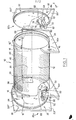
- the device according to the invention firstly comprises an enclosure 10 constituted by a cylinder 12 with a horizontal axis made of transparent polymethyl methacrylate.
- the cylinder is supported at its two ends by two feet 14a and 14b on which it is preferably glued.
- Each foot comprises a threaded rod 16 of éten- ant outwardly and identical threaded rods 1 6 'are also provided above the rods 16 on plate 18 glued on the edge of the cylinder openings in alignment vertical feet.
- each door of circular shape, comprises an exterior base panel 201 of relatively large thickness, an intermediate panel 202 and an interior panel 203.
- the panels are maintained at a determined spacing. relative to each other using appropriate spacers 21.
- the outer panel 201 is wider than the outer section of the cylinder 12 and has a flexible O-ring 22, for example glued, capable of coming into contact with the associated edge cylinder when the door is closed.
- the intermediate and interior panels have a diameter slightly smaller than the interior diameter of the cylinder and, in the closed position, the interior panel abuts against a second flexible O-ring 24 retained in the axial direction by an axial retaining element 26 of annular shape, made of polymethyl methacrylate.
- polymethyl methacrylate is advantageously chosen for the construction of the enclosure because of its excellent resistance to a wide variety of corrosive agents and because it exists in transparent form.
- a hinge 28 is mounted between a framework element 30 extending horizontally at the rear of the cylinder, for example fixed on an upper rear extension of each of the support legs 16a and 16b, and the associated external panel 201. Furthermore holes 32 are provided opposite the threaded rods 16, 16 'in radial extensions 201' of the outer panel 201 of each door, to receive the latter. In the closed position, wing nuts 34 engage the threaded rods 16, 16 ′ to tighten the associated door and compress the seals 22, 24, as shown in FIG. 2. It can be noted that the seals 22 and 24 serve to isolate the air spaces between the door panels from the outside and from the interior atmosphere of the enclosure, respectively. The enclosure is therefore perfectly gas tight, with optimal thermal insulation.
- the enclosure is provided with controlled heating means which first of all comprise a heating element 40 in the form of a resistive electric wire, preferably made of copper, wound helically in a complementary groove 42 provided at the outer periphery of the cylinder 12, over the entire length of the latter.
- the wire 40 will be supplied by an appropriate electric generator.
- a temperature probe element has the form of a second copper wire 44 extending in a helix in a groove 46 parallel to the first wire 40.
- the variations in temperature of this second wire 44 cause corresponding variations in its resistance, and it will be easy to design from the heating element and the sensor element a temperature regulation making it possible to maintain the temperature inside the enclosure at a chosen value, preferably between room temperature and 70 ° C.
- the heating means having the structure described above also have the effect of bringing the walls of the enclosure to a relatively uniform temperature of determined value, for the purposes explained below.
- the device further comprises smoke generating means by igniting a sample of material whose corrosivity of the smoke is to be measured. More specifically, a circular capsule 50 of silica is provided, a material chosen for its excellent resistance to thermal shock, at the bottom of which is wound in a spiral a resistor 52 constituted by a nickel-chrome alloy wire sheathed with a known material under the name "Inconel” (registered trademark), chosen for its good resistance to corrosion.
- the capsule 50 is mounted on the inner face of the door 20a, at the bottom of the latter, by means of a support rod 54, for example made of stainless steel.
- the two cold ends of the resistor 52 are connected to a connector 56 passing through the door and allowing said resistor to be connected to an appropriate current generator (not shown).
- the sample of the plastic material subjected to the test will advantageously be in the form of granules, of which a quantity determined with precision will be placed in the capsule 50.
- the electrical supply of the resistor 52 will moreover be designed to reach in the capsule a temperature sufficient to cause pyrolysis of the material.
- This device comprises a support 60 made of polymethyl methacrylate having the shape of a hollow parallelepiped in which is embedded a radiator formed of a copper plate (not visible), in however, leaving a cavity between the bottom of the support and the radiator. Cooling water is caused to circulate in this cavity, via inlet and outlet pipes, respectively 64 and 66, passing through the door 20b.
- a measuring test tube, schematically represented at 70, is placed in the support 60 so as to be in thermal contact with the radiator mentioned above.
- silicone grease will be used for this purpose.
- the test piece will advantageously have the form of a resistive electrical circuit carried by a support and preferably obtained by the etching technique well known in the field of printed circuits. It comprises a thin copper strip shaped as a serpentine on the support and ending in two wider conductive surfaces which will make it possible to connect the test piece, by two conductors 72, 74 passing through the door 20b, to a device for measuring the electrical resistance. (not shown).
- means are provided for generating inside the enclosure air having a well-determined humidity.
- These means comprise a dry air inlet duct 80 and an air intake duct 82 passing through the doors 20b and 20a respectively.
- These conduits will preferably be equipped with shut-off valves making it possible to interrupt the circulation of air at a predetermined instant.
- These means further comprise a third conduit 84, passing through the door 20b near the conduit 80, this third conduit normally being closed by a membrane (not shown).
- the desired humidity level is obtained by first circulating in the dry air enclosure, in order to determine a low point of the relative humidity inside it, for example less than 5%. A predetermined quantity of water is then introduced into the enclosure through the membrane, for example using a syringe, to obtain the desired degree of relative humidity before igniting the sample.
- the above device operates in the following manner: first of all, a predetermined quantity of the sample whose fumes are to be analyzed is placed in the silica capsule 50, in contact with the resistor 52, and at the same time in the support 60 a new test piece. The doors 20a and 20b are then closed and the heating means and the humid air generating means are used to obtain inside the enclosure an atmosphere of given temperature and humidity. The sample is then ignited by supplying the resistor 52, and the fumes and pyrolysis products formed will condense by natural convection on the cold surface of the test piece, this condensation being made possible by establishing a hygrometry. relatively high.
- condensation is carried out with very good selectivity because the largest part of the walls of the enclosure is maintained by the heating means at a determined temperature, of the order of 50 °, avoiding condensation on these walls.
- the value of the resistance of the test piece 70 is then measured and recorded periodically, and the importance of the corrosive effect of the fumes and pyrolysis products on the copper is deduced therefrom.
- this device will facilitate the choice of the most appropriate plastics, in particular in telephone exchanges, to minimize damage to the conductive circuits during a fire.
- the device described above and more particularly the structure of the enclosure and of its integrated controlled heating means, is advantageous in that it allows the condensation of smoke and of pyrolysis products obtained to be produced in a repeatable and reproducible manner. by burning plastic materials. More particularly, the invention allows a good control of the thermal cycle applied to the device, as well as a good selectivity of the condensation, in particular thanks to the great homogeneity of the temperature of the various walls of the enclosure, by not creating any undesirable condensation on cold parts other than the test piece.
- the structure of the invention while avoiding the hazards which were due in the prior art to the use of a climatic enclosure, allows the observation of condensation combustion and corrosion phenomena, which are, at side of the actual measurement, decisive elements for the choice of plastics.
Landscapes
- Life Sciences & Earth Sciences (AREA)
- Analytical Chemistry (AREA)
- General Physics & Mathematics (AREA)
- Environmental & Geological Engineering (AREA)
- Environmental Sciences (AREA)
- Physics & Mathematics (AREA)
- Health & Medical Sciences (AREA)
- Ecology (AREA)
- Biochemistry (AREA)
- Chemical & Material Sciences (AREA)
- General Health & Medical Sciences (AREA)
- Biodiversity & Conservation Biology (AREA)
- Immunology (AREA)
- Pathology (AREA)
- Investigating Or Analyzing Materials Using Thermal Means (AREA)
- Testing Resistance To Weather, Investigating Materials By Mechanical Methods (AREA)
Applications Claiming Priority (2)
| Application Number | Priority Date | Filing Date | Title |
|---|---|---|---|
| FR8610607 | 1986-07-22 | ||
| FR8610607A FR2602050B1 (fr) | 1986-07-22 | 1986-07-22 | Dispositif de mesure de la corrosivite des fumees |
Publications (3)
| Publication Number | Publication Date |
|---|---|
| EP0254637A2 true EP0254637A2 (de) | 1988-01-27 |
| EP0254637A3 EP0254637A3 (en) | 1989-05-24 |
| EP0254637B1 EP0254637B1 (de) | 1992-01-22 |
Family
ID=9337615
Family Applications (1)
| Application Number | Title | Priority Date | Filing Date |
|---|---|---|---|
| EP87401690A Expired - Lifetime EP0254637B1 (de) | 1986-07-22 | 1987-07-20 | Vorrichtung zum Messen der ätzenden Schärfe von Rauch |
Country Status (5)
| Country | Link |
|---|---|
| US (1) | US4789524A (de) |
| EP (1) | EP0254637B1 (de) |
| CA (1) | CA1273228A (de) |
| DE (1) | DE3776218D1 (de) |
| FR (1) | FR2602050B1 (de) |
Cited By (1)
| Publication number | Priority date | Publication date | Assignee | Title |
|---|---|---|---|---|
| FR2671172A1 (fr) * | 1990-12-31 | 1992-07-03 | Gaz De France | Procede et installation de simulation du fonctionnement d'un equipement de chauffage avec flamme utilisant un combustible fluide. |
Families Citing this family (3)
| Publication number | Priority date | Publication date | Assignee | Title |
|---|---|---|---|---|
| DE4329847C1 (de) * | 1993-09-03 | 1995-01-05 | Wagner Alarm Sicherung | Verfahren zum Erzeugen von Rauchaerosolen und Pyrolysegerät zur Durchführung des Verfahrens |
| GB0415862D0 (en) * | 2004-07-15 | 2004-08-18 | Boc Group Plc | Sensor |
| US8181504B2 (en) * | 2009-02-18 | 2012-05-22 | Factory Mutual Insurance Company | Smoke evaluating device and related method |
Family Cites Families (14)
| Publication number | Priority date | Publication date | Assignee | Title |
|---|---|---|---|---|
| US25932A (en) * | 1859-10-25 | haynes | ||
| USRE25932E (en) | 1965-12-07 | Corrosion testing mechanism | ||
| DE1147412B (de) * | 1960-03-30 | 1963-04-18 | Walter Pfeiffer | Verfahren und Geraete zur Untersuchung der Oberflaechenkorrosion metallischer Werkstoffe mittels EMK-Messung |
| DE1162107B (de) * | 1962-06-08 | 1964-01-30 | Siemens Reiniger Werke Ag | Korrosionspruefanlage |
| US3163497A (en) * | 1962-08-06 | 1964-12-29 | G S Equipment Company | Corrosion testing apparatus |
| US3259466A (en) * | 1962-12-28 | 1966-07-05 | Gen Motors Corp | Corrosive vapor test chamber |
| GB1356023A (en) * | 1971-02-10 | 1974-06-12 | Carroll Porczynski C Z | Falammability testing of materials |
| BE783143A (fr) * | 1972-05-05 | 1972-09-01 | Centre Rech Metallurgique | Dispositif pour essais de corrosion atmospherique. |
| DE2361709A1 (de) * | 1973-12-12 | 1975-06-26 | Volkswagenwerk Ag | Einrichtung zu korrosionstestzwecken |
| CH582356A5 (de) * | 1974-06-28 | 1976-11-30 | Sandoz Ag | |
| DE2537429C3 (de) * | 1975-08-22 | 1978-05-11 | Voetsch Gmbh, 6450 Hanau | Korrosionsprüfeinrichtung |
| JPS5272287A (en) * | 1975-12-12 | 1977-06-16 | Hitachi Ltd | Atmospheric corrosion tester |
| US4600695A (en) * | 1983-05-19 | 1986-07-15 | Wyle Laboratories | Sodium fire simulation process |
| US4683035A (en) * | 1986-02-03 | 1987-07-28 | Nalco Chemical Company | Method for in situ corrosion detection using electrochemically active compounds |
-
1986
- 1986-07-22 FR FR8610607A patent/FR2602050B1/fr not_active Expired
-
1987
- 1987-07-20 DE DE8787401690T patent/DE3776218D1/de not_active Expired - Lifetime
- 1987-07-20 EP EP87401690A patent/EP0254637B1/de not_active Expired - Lifetime
- 1987-07-20 US US07/075,171 patent/US4789524A/en not_active Expired - Fee Related
- 1987-07-21 CA CA000542582A patent/CA1273228A/fr not_active Expired - Lifetime
Cited By (1)
| Publication number | Priority date | Publication date | Assignee | Title |
|---|---|---|---|---|
| FR2671172A1 (fr) * | 1990-12-31 | 1992-07-03 | Gaz De France | Procede et installation de simulation du fonctionnement d'un equipement de chauffage avec flamme utilisant un combustible fluide. |
Also Published As
| Publication number | Publication date |
|---|---|
| EP0254637A3 (en) | 1989-05-24 |
| FR2602050B1 (fr) | 1988-11-10 |
| CA1273228A (fr) | 1990-08-28 |
| US4789524A (en) | 1988-12-06 |
| FR2602050A1 (fr) | 1988-01-29 |
| DE3776218D1 (de) | 1992-03-05 |
| EP0254637B1 (de) | 1992-01-22 |
Similar Documents
| Publication | Publication Date | Title |
|---|---|---|
| CA2089848A1 (fr) | Mesure de la resistivite electrique et de la conductivite thermique a haute temperature de produits refractaires | |
| WO2004065957A1 (fr) | Dispositif de mesure de la qualite et/ou de la degradation d'un fluide; notamment d'une huile alimentaire | |
| CH675634A5 (de) | ||
| EP0254637B1 (de) | Vorrichtung zum Messen der ätzenden Schärfe von Rauch | |
| CA3098473C (fr) | Dispositif de traitement thermique a enveloppe refractaire | |
| WO2008135368A1 (fr) | Dispositif de mesure capacitive de la qualite et/ou de la degradation d'un fluide | |
| EP2398364A2 (de) | Toaster | |
| EP0332505A1 (de) | Mikrowellenherd | |
| FR2714730A1 (fr) | Sonde à détecteur d'oxygène pour chaudière. | |
| WO2011131906A1 (fr) | Dispositif d'evaluation de fatigue thermomecanique d'un materiau | |
| EP0076759B1 (de) | Vorrichtung zur kontinuierlichen Bestimmung des Heizwertes von Gasen | |
| FR2859866A1 (fr) | Element resistif chauffant et ensemble chauffant comprenant cet element | |
| EP0487043B1 (de) | Verfahren zur Kühlung einer Stromzuleitung für elektrische Anlagen mit sehr niedrigen Temperaturen und Vorrichtung zur Durchführung des Verfahrens | |
| EP0422988B1 (de) | Verfahren und Vorrichtung zum Transport von Flüssigkeitsproben zwischen zwei Kammern und ihre Anwendung in der Gaschromatographie | |
| EP0184491A1 (de) | Wassererhitzer | |
| FR2685157A1 (fr) | Dispositif associe a un miroir pour eviter la formation de buee. | |
| CH645722A5 (fr) | Sonde pour la mesure de la pression partielle de l'oxygene dans une atmosphere de gaz. | |
| EP2350626A1 (de) | Element zum testen von materialien und verfahen zur charakterisierung unter verwendung dieses elements | |
| FR2461252A1 (fr) | Detecteur d'oxygene a electrolyte solide et procede de fabrication du detecteur | |
| EP1420612B1 (de) | Brenner für auf hoher Temperatur zu behandelndes Material | |
| FR3003945A1 (fr) | Sonde de temperature et ensemble comportant cette sonde | |
| FR2738063A1 (fr) | Installation d'essais de fatigue, en ambiance hygrothermique | |
| EP0239459A1 (de) | Thermometervorrichtung mit Umhüllung | |
| EP0438941A1 (de) | Vorrichtung und Verfahren zur Verhinderung von Korrosion eines metallischen isolierten Gehäuses | |
| FR2671172A1 (fr) | Procede et installation de simulation du fonctionnement d'un equipement de chauffage avec flamme utilisant un combustible fluide. |
Legal Events
| Date | Code | Title | Description |
|---|---|---|---|
| PUAI | Public reference made under article 153(3) epc to a published international application that has entered the european phase |
Free format text: ORIGINAL CODE: 0009012 |
|
| AK | Designated contracting states |
Kind code of ref document: A2 Designated state(s): DE GB |
|
| PUAL | Search report despatched |
Free format text: ORIGINAL CODE: 0009013 |
|
| AK | Designated contracting states |
Kind code of ref document: A3 Designated state(s): DE GB |
|
| 17P | Request for examination filed |
Effective date: 19891030 |
|
| 17Q | First examination report despatched |
Effective date: 19910313 |
|
| GRAA | (expected) grant |
Free format text: ORIGINAL CODE: 0009210 |
|
| AK | Designated contracting states |
Kind code of ref document: B1 Designated state(s): DE GB |
|
| REF | Corresponds to: |
Ref document number: 3776218 Country of ref document: DE Date of ref document: 19920305 |
|
| GBT | Gb: translation of ep patent filed (gb section 77(6)(a)/1977) | ||
| PGFP | Annual fee paid to national office [announced via postgrant information from national office to epo] |
Ref country code: DE Payment date: 19920629 Year of fee payment: 6 |
|
| PGFP | Annual fee paid to national office [announced via postgrant information from national office to epo] |
Ref country code: GB Payment date: 19920714 Year of fee payment: 6 |
|
| PLBE | No opposition filed within time limit |
Free format text: ORIGINAL CODE: 0009261 |
|
| STAA | Information on the status of an ep patent application or granted ep patent |
Free format text: STATUS: NO OPPOSITION FILED WITHIN TIME LIMIT |
|
| 26N | No opposition filed | ||
| PG25 | Lapsed in a contracting state [announced via postgrant information from national office to epo] |
Ref country code: GB Effective date: 19930720 |
|
| GBPC | Gb: european patent ceased through non-payment of renewal fee |
Effective date: 19930720 |
|
| PG25 | Lapsed in a contracting state [announced via postgrant information from national office to epo] |
Ref country code: DE Effective date: 19940401 |