EP0254739B1 - Vanne d'echantillonnage de liquide - Google Patents
Vanne d'echantillonnage de liquide Download PDFInfo
- Publication number
- EP0254739B1 EP0254739B1 EP19870900976 EP87900976A EP0254739B1 EP 0254739 B1 EP0254739 B1 EP 0254739B1 EP 19870900976 EP19870900976 EP 19870900976 EP 87900976 A EP87900976 A EP 87900976A EP 0254739 B1 EP0254739 B1 EP 0254739B1
- Authority
- EP
- European Patent Office
- Prior art keywords
- channel
- faces
- valve
- assembly according
- valve assembly
- Prior art date
- Legal status (The legal status is an assumption and is not a legal conclusion. Google has not performed a legal analysis and makes no representation as to the accuracy of the status listed.)
- Expired - Lifetime
Links
- 239000007788 liquid Substances 0.000 title claims abstract description 23
- 238000005070 sampling Methods 0.000 title 1
- 239000000463 material Substances 0.000 claims abstract description 4
- 238000007865 diluting Methods 0.000 claims abstract description 3
- 238000004891 communication Methods 0.000 claims description 8
- 238000007599 discharging Methods 0.000 claims description 2
- 238000011010 flushing procedure Methods 0.000 claims description 2
- 230000000903 blocking effect Effects 0.000 abstract 1
- 239000000523 sample Substances 0.000 description 15
- 239000003085 diluting agent Substances 0.000 description 11
- 238000004140 cleaning Methods 0.000 description 9
- 239000012530 fluid Substances 0.000 description 5
- 230000008878 coupling Effects 0.000 description 4
- 238000010168 coupling process Methods 0.000 description 4
- 238000005859 coupling reaction Methods 0.000 description 4
- 210000002445 nipple Anatomy 0.000 description 4
- 239000008280 blood Substances 0.000 description 1
- 210000004369 blood Anatomy 0.000 description 1
- 239000000919 ceramic Substances 0.000 description 1
- 238000010276 construction Methods 0.000 description 1
- 238000010790 dilution Methods 0.000 description 1
- 239000012895 dilution Substances 0.000 description 1
- 238000001035 drying Methods 0.000 description 1
- 230000000694 effects Effects 0.000 description 1
- 238000012423 maintenance Methods 0.000 description 1
- 238000005259 measurement Methods 0.000 description 1
- 230000002028 premature Effects 0.000 description 1
- 239000000243 solution Substances 0.000 description 1
- 238000005406 washing Methods 0.000 description 1
Images

Classifications
-
- G—PHYSICS
- G01—MEASURING; TESTING
- G01N—INVESTIGATING OR ANALYSING MATERIALS BY DETERMINING THEIR CHEMICAL OR PHYSICAL PROPERTIES
- G01N35/00—Automatic analysis not limited to methods or materials provided for in any single one of groups G01N1/00 - G01N33/00; Handling materials therefor
- G01N35/10—Devices for transferring samples or any liquids to, in, or from, the analysis apparatus, e.g. suction devices, injection devices
- G01N35/1095—Devices for transferring samples or any liquids to, in, or from, the analysis apparatus, e.g. suction devices, injection devices for supplying the samples to flow-through analysers
- G01N35/1097—Devices for transferring samples or any liquids to, in, or from, the analysis apparatus, e.g. suction devices, injection devices for supplying the samples to flow-through analysers characterised by the valves
-
- G—PHYSICS
- G01—MEASURING; TESTING
- G01N—INVESTIGATING OR ANALYSING MATERIALS BY DETERMINING THEIR CHEMICAL OR PHYSICAL PROPERTIES
- G01N1/00—Sampling; Preparing specimens for investigation
- G01N1/28—Preparing specimens for investigation including physical details of (bio-)chemical methods covered elsewhere, e.g. G01N33/50, C12Q
- G01N1/38—Diluting, dispersing or mixing samples
-
- Y—GENERAL TAGGING OF NEW TECHNOLOGICAL DEVELOPMENTS; GENERAL TAGGING OF CROSS-SECTIONAL TECHNOLOGIES SPANNING OVER SEVERAL SECTIONS OF THE IPC; TECHNICAL SUBJECTS COVERED BY FORMER USPC CROSS-REFERENCE ART COLLECTIONS [XRACs] AND DIGESTS
- Y10—TECHNICAL SUBJECTS COVERED BY FORMER USPC
- Y10T—TECHNICAL SUBJECTS COVERED BY FORMER US CLASSIFICATION
- Y10T137/00—Fluid handling
- Y10T137/4238—With cleaner, lubrication added to fluid or liquid sealing at valve interface
- Y10T137/4245—Cleaning or steam sterilizing
- Y10T137/4259—With separate material addition
Definitions
- This invention relates generally to liquid transfer valves for measuring and dispensing precise microliter volumes of liquid samples and of the type which includes coaxially arranged disc members having opposite faces frictionally engaged and at least one disc member being rotatable relative to the other.
- the invention provides internal passage means formed in select facing surfaces of said valve elements for isolating the passageways from the periphery of said valve elements so as to prevent liquid from reaching the circumferencial exterior of the valve along said facing surfaces.
- EP-A-0 136 550 discloses a sample segmenting and mixing apparatus for fluid media.
- One example of the apparatus comprises an upper stationary element, an intermediate movable element, and a lower stationary element.
- the upper stationary element defining one part of a two part delivery element, is constructed as a circular disk, and is provided with a plurality of through-flow passages or openings comprising first and second circulation passages as well as first and second transfer passages, and also with a central bore.
- the lower stationary element defining the other part of the two part delivery element, is also constructed as a circular disc with a plurality of through-flow passages or openings defining first and second circulation passages and first and second transfer passages as well as with a central bore.
- the intermediate movable element defining an isolating or segmenting element, is constructed as a circular disc in contact with and between the upper and lower elements.
- An outer annular channel as well as an inner annular channel is provided on each of the lower and upper surfaces, respectively, of the isolating element facing the upper and lower elements.
- the inner annular channel and the outer annular channel are inter-connected by a respective cross channel.
- a dosing or segmenting chamber is provided in the intermediate element immediately in the region of the cross channel.
- the circulation passages in the upper element communicate with the annular channels in the upper face of the intermediate element and the circulation passages in the lower element communicate with the annular channels of the lower face of the intermediate element.
- the dosing chamber coincides or registers with the transfer passages of the upper and lower elements.
- the present invention provides a liquid diluting and transfer valve assembly of the type which includes at least a pair of valve elements, each being frictionally movable one relative to the other and having faces slidably engaged for such frictional movement, each valve element having axial measuring and segmenting passageways therethrough arranged for selective communication in junctions at the faces when at least one valve element is rotated; and a continuous channel formed in one of said faces along a path extending substantially along the periphery of said face but spaced inwardly thereof, said channel being capable of intercepting any liquid traversing the faces, said channel having an inlet, an outlet and bore means, formed in the valve element carrying the channel, communicating with said inlet and outlet and capable respectively of receiving and discharging rinse liquid from a source thereof, flushing said channel of any material accumulating therein, characterised in that said channel is non-interferent with any of the passageway openings.
- the invention herein will be described as employed in liquid transfer valve constructions which include at least a pair of valve elements having frictionally engaged faces. Passageways formed in the valve discs communicate at their junctions and liquid is passed through said passageways. The junctions of the passageways occur at the engaged faces, with rotation of the valve element causing shifting of the passageways changing the communication of one with another.
- a continuous cleaning channel is formed in one element face, preferably one of the sandwiching disc faces, the channel functioning as a cleaning channel arranged to isolate the passageway junctions from the periphery of the engaged faces whereby to collect any leakage which may occur at the junctions preventing passage thereof to the periphery of the faces.
- Suitable passageway and port means are formed in the valve element communicating with the opposite ends of the continuous channel whereby rinsing can be effected by introducing the rinse fluid at one end for discharge at the opposite end.
- the liquid transfer valve assembly contemplated herein is capable of delivering from a single sample at least two microliter segments, preferably simultaneously, for dilution with predetermined volumes of diluent.
- the segments are of different volume respectively.
- Passages are provided for establishing two sets of fluid paths, one set defining paths for traversal by a predetermined volume of diluent, the other set defining a series connection of a pair of precise measuring chambers of different volumes, one of which is provided by a segmenting passageway formed in the inner or movable valve element and the other being provided by an external hollow loop secured fixedly to one of the stationary members.
- the external loop and the segmenting passageways have precise internal dimensions, preferably holding a volume in the microliter range.
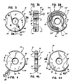
- the valve assembly illustrated in FIGURES 1 through 4A and 4B is formed of a pair of members sealingly engaged with an inner movable member sandwiched therebetween.
- the valve assembly operates between a first condition during which sample is introduced from a source by way of an aspirator probe driven by an aspiration pump and a second or delivery condition.
- the aspirator probe can be coupled directly or through a conduit system, to a stationary portion of the valve.
- a continuous path is established between the aspirating probe via a segmenting passageway (constituting a second measuring chamber) through a connecting passageway, leading to the aspiration pump.
- the valve assembly is operated to place same in the delivery condition, thereby placing the volume segmented from the continuous path by the segmenting passageway into a path established to direct diluent thereto for delivery from the valve to a selected location.
- the volume of sample contained in the second measuring chamber (namely the internal volume of the external loop) is coupled to a path through which diluent is introduced to sweep said volume of sample from second measuring chamber for delivery to a second preselected location.
- valve assembly 10 constructed in accordance with the invention as illustrated in FIGURES 1 to 4B inclusive comprises as assembly 10 formed of a pair of coaxially arranged outer stationary disc elements 12 and 16 having a rotatably movable central valve disc element 14 sandwiched therebetween.
- the stationary elements 12 and 16 are arranged apart only sufficiently to accommodate the thinner central element therebetween.
- the outer elements 12 and 16 are provided with inner faces 12′ and 16′ which are engaged sealingly with faces 14′ and 14 ⁇ of the inner element 14.
- Element 12 also has an outer face 12 ⁇ and element 16 has outer face 16 ⁇ .
- Faces 12′, 14′, 14 ⁇ and 16′ are machined carefully and stress relieved as by heat. All faces are provided with a hard ceramic surface to reduce friction or binding.
- Each of the valve disc elements 12, 14 and 16 have central passageway 18 of the same inner diameter and all are mounted coaxially on the spindle 20 including support elements 22 and 24 and shaft 26.
- the left hand element 12 carries the external hollow loop while the right hand element 16 carries either the aspirator probe directly coupled thereto or has the aspirator probe adapted to be coupled thereto by way of a conduit coupling.
- a pair of axially parallel through passageways 30 and 32 are formed in stationary outer disc element 12.
- Another through passageway 34 is formed in disc element 12 parallel axially to the passageways 30 and 32 but angularly spaced therefrom so that a radial line taken through the axial center of passageway 34 defines a precise angle 0 with a radial line taken through the axial center of passageway 32.
- the passageway 34 includes a short portion 34′ of small diameter opening to the inner face 12′ while the larger diameter portion 34′ opens to the outer face 12" for receiving nipple 36 for coupling to a source of diluent.
- Passageways 30 and 32 each have a major portion 30 ⁇ and 32 ⁇ of larger diameter compared to the short portions 30′ and 32′, each of which opens to the inner face 12′.
- the larger diameter portions 30′ 32′ open to the outer face 12 ⁇ of element 12.
- Passageway portions 30 ⁇ and 32 ⁇ have the same inner diameter.
- An external hollow loop 38 is secured to the element 12 with opposite ends 38′ seated tightly fully in the larger diameter passageway portions 30 ⁇ and 32 ⁇ .
- the external loop 38 has a precise internal volume.
- the inner diameter of the hollow loop 38 preferably is uniform with opposite ends 38′ having an inner diameter equal to the diameter of the smaller passageway portions 30′ and 32′ of passageways 30 and 32.
- the ends 38′ are inserted fully within passageway portions 30 ⁇ and 32 ⁇ to about the inner ends of passageway portions 30 ⁇ and 32 ⁇ .
- a precise volume of liquid can be contained within the measuring chamber 40 defined within the hollow external loop.
- the stationary valve elements 12 and 16 are provided with circumferential notches 42 and 44 while center valve element 14 is provided with a notch 46 of the same depth but encompassing a greater angular distance along the circumferential opening length than the angular extent of notches 42 and 44.
- Notches 42 and 44 are aligned with the opposite sides of said notches limiting the relative angular rotation of the center valve element 14 to an angular distance equal to the difference between the length of notches 42, 44 and the length of notch 46.
- the angular rotation of the center valve element 14 required to change the valve assembly 10 from one condition to its other condition is represented by angle 0.
- valve elements 12, 14 and 16 When the valve elements 12, 14 and 16 are assembled to constitute the valve assembly 10, all of the axially directed passageways and portions thereof which communicate with other passageways carried by the valve elements are coaxial, and all are parallel to the common center axis of said elements 12, 14 and 16. Valve elements 12, 14 and 16 are mounted coaxially on spindle 20.
- a pair of like axially parallel passageways 48 and 50 are formed in the other stationary valve element 16, each passageway 48 and 50 having a larger diameter long portion 48 ⁇ and 50 ⁇ opening to the outer face 16 ⁇ of element 16 with smaller diameter short portion 48′ and 50′ opening to the inner face 16′ of element 16.
- a cylindrical nipple 52 is tightly seated within each of the large portions 48′ and 50′ extending outward of element 16 and opening to the exterior of the valve for coupling to the aspirator pump P and to suitable conduits leading to one of the preselected delivery locations, here to the location intended to receive the smaller segmented volume of sample.
- the stationary valve element 16 also is provided with a radial bore 54 opening to the outer circumferential surface of the element 16.
- the inner end 54′ of bore 54 communicates with a short axial bore 55 formed parallel to the axis of the valve element 16 and opening to the inner face 16′ thereof.
- bores 54 and 55 together constitute an angular passageway 58.
- the aspirator probe 60 is adapted to be coupled directly to the bore 54 by a conduit, or directly received within bore 54.
- the rotatably movable center valve disc element 14 is provided with two pair of passageways, first pair 64 (including bore 74), 66 and second pair 68 (including bore 72), 70.
- Passageway 66 is formed as a through passageway of precise uniform inner diameter while passageways 64 and 68 extend in an axial direction only partially through the valve element 14 from face 14′ of said element.
- the radial bores 72 and 74 are provided in element 14 entering from the outer circumferential surface 76 thereof and communicating to the inner end 64′ and 68′ of the partial passageways 64 and 68.
- the inner diameter of bores 72 and 74 is sufficient to enable seating therein of nipples 78 and 80, one of which is capable of being coupled to a conduit 82 leading to the preselected delivery location for receiving the larger volume of sample which comprises the interior volume of the hollow loop 38 and the other nipple 80 enabling coupling thereto of a conduit 82 leading from a source S2 of diluent for directing the predetermined volume of diluent to the hollow loop 38 when the valve element 14 is rotated to place the valve 10 in its delivery condition from its load condition.
- Passageway 70 serves only as a communication channel to the pump, holding its content when rotated for delivery of the measured content of loop 38 and passageways 30, 32.
- the through segmenting passageway 66 which defines the smaller measuring chamber is brought into communication with the passageways 34, 59 enabling a predetermined volume of diluent from source S1 to be introduced via passageway 34 to drive the content of the segmenting passageway 66 to the predetermined location via passageway 50 of valve element 16.
- the hollow loop 38 is aligned with passageways 64, 68 enabling a predetermined volume of diluent to be directed through the hollow loop 38 to deliver the contents of the loop to a predetermined location.
- the disc 12 is provided with a through passageway 73 which will couple with bore 72 in element 14, leading out of valve 10.
- the element 14 has a through passage 69 which, in the backwash condition of the valve, will connect with passageways 34 and 50 in the front and rear elements 12, 16 respectively.
- rinse fluid can be applied from the left side of FIGURE 1 into the passageway 73 (as well as into the said passageway 34), which leads into the passageways 69 and bore 72, then out of the valve 10 at selected locations.
- the valve 10 returns to the original aspiration condition but fulfills the backwash mode of operation.
- the element 14 has been rotated after the delivery has been completed, to place passageway 73 in communication with the passageway defined by bores 68, 72 of element 14. In this condition, the passageway defined by bores 64, 74 is placed out of communication with passageway 30.
- the sample in passageway 66 has been delivered with passageway 66 being returned to communicate to the passageway 58 leading to the probe 60.
- Passageway 69 is returned to communicate with passageways 34 and 50.
- Passageway 70, with its isolated content, is returned to communication with passageways 48 and 30.
- the rinse liquid is directed from a source through the aligned passageways of the valve 10 to predetermined locations.
- Passageways 34, 50 provide means of rinsing passageway 69 in the backwash or rinse mode.
- Passageway 73 is provided to permit rinse or backwash of the passageway defined by bores 68, 72 in element 14.
- FIGURES 2 and 2A as well as FIGURES 3A and 3B wherein there is illustrated, as formed in the faces 12′ and 16′ of the valve elements 12 and 16 respectively, the continuous cleaning channels 100 and 102 which are similar in configuration.
- Channel 100 is formed in the face 12′ and consists of a first or outer groove 104 beginning at passage 106 and extending in a clockwise direction to a location 108 approximately 245° of rotation form its point of origin.
- the 245° extension of the channel 100 is placed precisely on face 12′ so that no portion of channel 100 is exposed regardless of the angular position of element 14.
- the second or inner groove 110 follows a circular path concentric to the center of the face 12′ and to the outer groove 104.
- the groove 110 extends counter-clockwise along a path toward passage or bore 112.
- the grooves 104 and 110 are formed along the greater portions of a pair of concentric circles and spaced radially apart a distance of .04 radians along a line taken from the center of the face 12′.
- Bridging or connecting channel or groove 114 completes the continuous channel 100 connecting the inner and outer portions thereof.
- the opposite sides of both channels 100 and 102 are chamfered at about 45°.
- Bore 112 is formed in the element 12 and opens to larger diameter coaxial passage 116. Bore 112 is located at the terminus of the inner portions of continuous channel 100.
- the bore 106 is located at the beginning of the outer portion of the continuous channel 100.
- the center of bore 112 is offset from the center of the channel portion 100.
- Channel 102 is identical to channel 100 and is illustrated in FIGURE 3B.
- the continuous cleaning channel 102 formed in face 16′ of element 16 is substantially identical to the configuration of channel 100.
- Channel 102 is formed of outer channel 104′ and inner channel 110′ originating from bore 106′ and terminating at bore 112′ and joined by arcuate groove 114′.
- the channels 104′, 110′ and 114′ are chamfered along their sides in the same manner as continuous cleaning channel 100.
- the entry of rinse fluid is effected via passage 118, bore 106 entering the outer portion 104 of the continuous channel 100 and exiting at passage 116.
- the chamfered walls of the continuous channel 100 affords smooth flow of rinsing liquids through said channel, washing free any material which may have been collected on said walls or within the channel.
- the continuous cleaning channels 100, 102 isolate the junctions of the respective segmenting passageways 66, 68, 69 and 70 from the periphery of the respective faces 12′ and 16′ which frictionally engage faces 14′ and 14 ⁇ of the central rotatable element 14.
- Continuous cleaning channel 100 of like configuration and path also may be provided in respective opposite faces of the center valve element 14 if desired.
- the rinsing step of the valve operation may be effected at the same time as the backwash operation cycle of the liquid transfer system.
- the invention contemplates the provision of the continuous cleaning channel of the invention in a valve where the measuring passageways are in other than series connection; in a valve where more than one pair of volumes or measuring chambers are provided and it is not required to be limited to measurement of identical volumes of samples or identical volumes of diluent.
Landscapes
- Physics & Mathematics (AREA)
- Health & Medical Sciences (AREA)
- Life Sciences & Earth Sciences (AREA)
- Chemical & Material Sciences (AREA)
- Analytical Chemistry (AREA)
- Biochemistry (AREA)
- General Health & Medical Sciences (AREA)
- General Physics & Mathematics (AREA)
- Immunology (AREA)
- Pathology (AREA)
- Sampling And Sample Adjustment (AREA)
- Automatic Analysis And Handling Materials Therefor (AREA)
- Multiple-Way Valves (AREA)
- Devices For Use In Laboratory Experiments (AREA)
Claims (12)
Priority Applications (1)
| Application Number | Priority Date | Filing Date | Title |
|---|---|---|---|
| AT87900976T ATE69740T1 (de) | 1986-01-16 | 1987-01-15 | Ventil zur musternahme einer fluessigkeit. |
Applications Claiming Priority (2)
| Application Number | Priority Date | Filing Date | Title |
|---|---|---|---|
| US06/819,381 US4702889A (en) | 1986-01-16 | 1986-01-16 | Liquid sampling valve |
| US819381 | 1986-01-16 |
Publications (3)
| Publication Number | Publication Date |
|---|---|
| EP0254739A1 EP0254739A1 (fr) | 1988-02-03 |
| EP0254739A4 EP0254739A4 (fr) | 1988-11-14 |
| EP0254739B1 true EP0254739B1 (fr) | 1991-11-27 |
Family
ID=25227997
Family Applications (1)
| Application Number | Title | Priority Date | Filing Date |
|---|---|---|---|
| EP19870900976 Expired - Lifetime EP0254739B1 (fr) | 1986-01-16 | 1987-01-15 | Vanne d'echantillonnage de liquide |
Country Status (11)
| Country | Link |
|---|---|
| US (1) | US4702889A (fr) |
| EP (1) | EP0254739B1 (fr) |
| JP (1) | JPH0654285B2 (fr) |
| CN (1) | CN1007659B (fr) |
| AT (1) | ATE69740T1 (fr) |
| AU (1) | AU584491B2 (fr) |
| CA (1) | CA1279775C (fr) |
| DE (1) | DE3774791D1 (fr) |
| ES (1) | ES2004056A6 (fr) |
| IL (1) | IL81251A (fr) |
| WO (1) | WO1987004370A1 (fr) |
Families Citing this family (48)
| Publication number | Priority date | Publication date | Assignee | Title |
|---|---|---|---|---|
| US4822569A (en) * | 1986-06-09 | 1989-04-18 | Fisher Scientific Company | Rotary shear valve with cleaning feature and method of using same |
| US4896546A (en) * | 1987-10-26 | 1990-01-30 | Coulter Electronics, Inc. | Liquid metering and transfer valve assembly |
| US5093083A (en) * | 1988-06-22 | 1992-03-03 | Serono-Baker Diagnostics, Inc. | Method for controlling the environment in a liquid diluting and transfer valve assembly |
| US5132012A (en) * | 1988-06-24 | 1992-07-21 | Hitachi, Ltd. | Liquid chromatograph |
| US4957008A (en) * | 1988-12-28 | 1990-09-18 | Coulter Electronics, Inc. | Fluid sampling and transfer valve assembly |
| US4948565A (en) * | 1989-04-25 | 1990-08-14 | Fisher Scientific Company | Analytical system |
| US5089234A (en) * | 1989-08-09 | 1992-02-18 | Serono-Baker Diagnostics, Inc. | Controlled environment liquid diluting and transfer valve assembly |
| DE4014602A1 (de) * | 1990-05-07 | 1991-11-14 | Max Planck Gesellschaft | Dosiervorrichtung mit radialer anordnung von ventilen |
| JP2527276Y2 (ja) * | 1990-10-24 | 1997-02-26 | 三菱重工業株式会社 | スラリーのサンプリング装置 |
| DE59105165D1 (de) * | 1990-11-01 | 1995-05-18 | Ciba Geigy Ag | Vorrichtung zur Aufbereitung oder Vorbereitung von flüssigen Proben für eine chemische Analyse. |
| US5255568A (en) * | 1990-12-13 | 1993-10-26 | Coulter Corporation | Liquid sample/reagent metering and delivery method |
| US5158751A (en) * | 1990-12-13 | 1992-10-27 | Coulter Corporation | Liquid metering and transfer valve assembly |
| JP3130608B2 (ja) * | 1991-11-20 | 2001-01-31 | シスメックス株式会社 | サンプリングバルブ |
| JP2589997Y2 (ja) * | 1993-02-17 | 1999-02-03 | シスメックス株式会社 | サンプリングバルブ |
| DE4318919A1 (de) * | 1993-06-07 | 1994-12-08 | Bodenseewerk Perkin Elmer Co | Probendosiersystem |
| US5441071A (en) * | 1994-05-04 | 1995-08-15 | Mclane Research Laboratories, Inc. | Automated water sample collecting system |
| US6190616B1 (en) | 1997-09-11 | 2001-02-20 | Molecular Dynamics, Inc. | Capillary valve, connector, and router |
| US6228652B1 (en) | 1999-02-16 | 2001-05-08 | Coulter International Corp. | Method and apparatus for analyzing cells in a whole blood sample |
| US6322752B1 (en) | 1999-09-08 | 2001-11-27 | Coulter International Corp. | Method and apparatus for aspirating and dispensing liquids |
| US6431202B1 (en) * | 1999-12-01 | 2002-08-13 | Calgon Carbon Corporation | Fluid-directing multiport rotary valve |
| DE10013528C1 (de) | 2000-03-20 | 2001-09-20 | Brand Gmbh & Co Kg | Dosiervorrichtung für insbesondere zähflüsige Flüssigkeiten |
| US6890489B2 (en) * | 2000-04-26 | 2005-05-10 | Rheodyne, L.P. | Mass rate attenuator |
| US6374684B1 (en) * | 2000-08-25 | 2002-04-23 | Cepheid | Fluid control and processing system |
| US8048386B2 (en) | 2002-02-25 | 2011-11-01 | Cepheid | Fluid processing and control |
| US7135146B2 (en) * | 2000-10-11 | 2006-11-14 | Innovadyne Technologies, Inc. | Universal non-contact dispense peripheral apparatus and method for a primary liquid handling device |
| US6852291B1 (en) * | 2000-10-11 | 2005-02-08 | Innovadyne Technologies, Inc. | Hybrid valve apparatus and method for fluid handling |
| US6613284B2 (en) * | 2001-02-01 | 2003-09-02 | V&P Scientific, Inc. | Microarrayer |
| US6872361B2 (en) * | 2001-06-28 | 2005-03-29 | Coulter International Corp. | Dual pad liquid shear valve assembly |
| JP2005516220A (ja) | 2002-01-25 | 2005-06-02 | イノベイダイン・テクノロジーズ・インコーポレーテッド | 低容量かつ非接触な液体の分注方法 |
| US6662826B1 (en) | 2002-10-07 | 2003-12-16 | Abbott Laboratories | Liquid metering and transfer valve assembly with port switch |
| US7032605B1 (en) | 2003-10-15 | 2006-04-25 | Douglas B. Dority | Dual piston rotary valve |
| DK175721B1 (da) * | 2003-10-28 | 2005-02-07 | Keofitt As | Ventil til steril udtagning af en væskepröve fra en beholder |
| JP4040586B2 (ja) * | 2004-02-20 | 2008-01-30 | シャープ株式会社 | 原稿搬送装置およびこれを用いた原稿自動読取り装置 |
| EP1789708B1 (fr) * | 2004-08-25 | 2011-10-19 | Mécanique Analytique Inc. | Soupape rotative et systeme chromatique d'analyse utilisant cette soupape rotative |
| WO2009003521A1 (fr) | 2007-07-04 | 2009-01-08 | Agilent Technologies, Inc. | Vanne à cisaillement à élément stratifié |
| AT9603U3 (de) * | 2007-08-16 | 2008-08-15 | Avl List Gmbh | Rotationsverdünner für fluidströme |
| US8567441B2 (en) * | 2007-09-28 | 2013-10-29 | Shimadzu Corporation | Sample introduction device |
| CN101418865B (zh) * | 2007-10-22 | 2010-12-22 | 深圳迈瑞生物医疗电子股份有限公司 | 旋转集成阀 |
| WO2010115192A2 (fr) * | 2009-04-03 | 2010-10-07 | Integrated Nano-Technologies, Inc. | Soupape rotative à plusieurs chambres |
| US9347086B2 (en) | 2009-04-03 | 2016-05-24 | Integrated Nano-Technologies, Llc | Method and system for sample preparation |
| WO2014047108A1 (fr) * | 2012-09-20 | 2014-03-27 | Waters Technologies Corporation | Valve sélectrice rotative et systèmes et procédés associés |
| CA2888316C (fr) * | 2012-10-17 | 2021-05-04 | Integrated Nano-Technologies, Llc | Procede et systeme pour la preparation d'echantillons |
| TR201808927T4 (tr) * | 2015-02-25 | 2018-07-23 | Fluehs Drehtechnik Gmbh | Valf üst parçası. |
| CN104806784A (zh) * | 2015-04-11 | 2015-07-29 | 苏州卫水环保科技有限公司 | 一种多通阀盘 |
| WO2016166089A1 (fr) * | 2015-04-14 | 2016-10-20 | Keofitt A/S | Dispositif d'échantillonnage permettant de prélever des échantillons de fluide à partir d'un récipient de fluide |
| CN105351548B (zh) * | 2015-11-20 | 2017-09-15 | 浙江泛泰仪器有限公司 | 一种在线快速取样阀 |
| US11035480B2 (en) * | 2016-02-24 | 2021-06-15 | Leanna Levine and Aline, Inc. | Mechanically driven sequencing manifold |
| CN113531157B (zh) * | 2021-07-08 | 2023-07-07 | 卡奥斯能源科技有限公司 | 一种分布式能源管理用环境监控装置 |
Family Cites Families (13)
| Publication number | Priority date | Publication date | Assignee | Title |
|---|---|---|---|---|
| FR2121827A1 (en) * | 1971-01-15 | 1972-08-25 | Aga Ab | Multiple micro-pipette - with stacked valve discs rotated about common axis |
| US3885439A (en) * | 1973-10-24 | 1975-05-27 | Hoffmann La Roche | Rotating sampling valve |
| US3964513A (en) * | 1975-04-08 | 1976-06-22 | Hoffmann-La Roche Inc. | Rotating sampling valve |
| US4152391A (en) * | 1977-12-16 | 1979-05-01 | Coulter Electronics, Inc. | Liquid transfer valve |
| DE3107429C2 (de) * | 1981-02-27 | 1986-11-20 | Otto Tuchenhagen GmbH & Co KG, 2059 Büchen | Reinigbares Probenentnahmeventil |
| US4458541A (en) * | 1981-10-13 | 1984-07-10 | Beckman Instruments, Inc. | Liquid sample injection valve for gas chromatographs |
| US4507977A (en) * | 1981-10-19 | 1985-04-02 | Coulter Electronics, Inc. | Liquid metering and transfer valve assembly |
| US4445391A (en) * | 1981-10-19 | 1984-05-01 | Coulter Electronics, Inc. | Liquid metering and transfer valve assembly |
| DE3211692A1 (de) * | 1982-03-30 | 1983-10-06 | Holstein & Kappert Maschf | Verfahren zum reinigen von hohlraeumen in doppelsitzventilen |
| SE453754B (sv) * | 1982-06-15 | 1988-02-29 | Gambro Lundia Ab | Anordning for metning av koncentrationen av en lagmolekyler forening i ett komplext medium |
| CH674580A5 (fr) * | 1983-10-06 | 1990-06-15 | Contraves Ag | |
| US4577515A (en) * | 1984-06-19 | 1986-03-25 | Tokyo Rika Kikai Co., Ltd. | Sampling valve for use in high-speed liquid chromatography |
| US4562748A (en) * | 1984-08-16 | 1986-01-07 | The United States Of America As Represented By The United States Department Of Energy | Disc valve for sampling erosive process streams |
-
1986
- 1986-01-16 US US06/819,381 patent/US4702889A/en not_active Expired - Lifetime
-
1987
- 1987-01-13 IL IL8125187A patent/IL81251A/xx not_active IP Right Cessation
- 1987-01-15 EP EP19870900976 patent/EP0254739B1/fr not_active Expired - Lifetime
- 1987-01-15 WO PCT/US1987/000113 patent/WO1987004370A1/fr not_active Ceased
- 1987-01-15 JP JP50093887A patent/JPH0654285B2/ja not_active Expired - Lifetime
- 1987-01-15 DE DE8787900976T patent/DE3774791D1/de not_active Expired - Lifetime
- 1987-01-15 AU AU68490/87A patent/AU584491B2/en not_active Ceased
- 1987-01-15 AT AT87900976T patent/ATE69740T1/de not_active IP Right Cessation
- 1987-01-15 CA CA 527414 patent/CA1279775C/fr not_active Expired - Lifetime
- 1987-01-16 CN CN87100821A patent/CN1007659B/zh not_active Expired
- 1987-01-16 ES ES8700096A patent/ES2004056A6/es not_active Expired
Also Published As
| Publication number | Publication date |
|---|---|
| DE3774791D1 (de) | 1992-01-09 |
| EP0254739A1 (fr) | 1988-02-03 |
| US4702889A (en) | 1987-10-27 |
| CN87100821A (zh) | 1987-09-16 |
| WO1987004370A1 (fr) | 1987-07-30 |
| IL81251A0 (en) | 1987-08-31 |
| CA1279775C (fr) | 1991-02-05 |
| EP0254739A4 (fr) | 1988-11-14 |
| ATE69740T1 (de) | 1991-12-15 |
| AU6849087A (en) | 1987-08-14 |
| IL81251A (en) | 1989-12-15 |
| JPS63502454A (ja) | 1988-09-14 |
| JPH0654285B2 (ja) | 1994-07-20 |
| CN1007659B (zh) | 1990-04-18 |
| ES2004056A6 (es) | 1988-12-01 |
| AU584491B2 (en) | 1989-05-25 |
Similar Documents
| Publication | Publication Date | Title |
|---|---|---|
| EP0254739B1 (fr) | Vanne d'echantillonnage de liquide | |
| US4445391A (en) | Liquid metering and transfer valve assembly | |
| US4507977A (en) | Liquid metering and transfer valve assembly | |
| US5650577A (en) | Liquid sampling valve | |
| US4957008A (en) | Fluid sampling and transfer valve assembly | |
| CA1089648A (fr) | Robinet de transvasage | |
| JP3150965B2 (ja) | 液体計量及び移送バルブ組立体 | |
| US4726237A (en) | Fluid metering apparatus and method | |
| US4625569A (en) | Liquid injection device | |
| US4726932A (en) | Dosing and mixing apparatus for fluid media | |
| US6662826B1 (en) | Liquid metering and transfer valve assembly with port switch | |
| EP0515642B1 (fr) | Ensemble vanne de dosage et de transfert de liquide | |
| CA1178086A (fr) | Pompe volumetrique avec compteur volmetrique incorpore | |
| US5255568A (en) | Liquid sample/reagent metering and delivery method | |
| GB1595885A (en) | Automatic chemical analyzer | |
| JPS60154160A (ja) | 遠心試料の分注、測定機構 | |
| CA1313105C (fr) | Robinet doseur/coupleur pour liquides |
Legal Events
| Date | Code | Title | Description |
|---|---|---|---|
| PUAI | Public reference made under article 153(3) epc to a published international application that has entered the european phase |
Free format text: ORIGINAL CODE: 0009012 |
|
| AK | Designated contracting states |
Kind code of ref document: A1 Designated state(s): AT BE CH DE FR GB IT LI LU NL SE |
|
| 17P | Request for examination filed |
Effective date: 19880118 |
|
| A4 | Supplementary search report drawn up and despatched |
Effective date: 19881114 |
|
| 17Q | First examination report despatched |
Effective date: 19900914 |
|
| ITF | It: translation for a ep patent filed | ||
| GRAA | (expected) grant |
Free format text: ORIGINAL CODE: 0009210 |
|
| AK | Designated contracting states |
Kind code of ref document: B1 Designated state(s): AT BE CH DE FR GB IT LI LU NL SE |
|
| PG25 | Lapsed in a contracting state [announced via postgrant information from national office to epo] |
Ref country code: AT Effective date: 19911127 |
|
| REF | Corresponds to: |
Ref document number: 69740 Country of ref document: AT Date of ref document: 19911215 Kind code of ref document: T |
|
| REF | Corresponds to: |
Ref document number: 3774791 Country of ref document: DE Date of ref document: 19920109 |
|
| PG25 | Lapsed in a contracting state [announced via postgrant information from national office to epo] |
Ref country code: LU Free format text: LAPSE BECAUSE OF NON-PAYMENT OF DUE FEES Effective date: 19920131 |
|
| ET | Fr: translation filed | ||
| PLBE | No opposition filed within time limit |
Free format text: ORIGINAL CODE: 0009261 |
|
| STAA | Information on the status of an ep patent application or granted ep patent |
Free format text: STATUS: NO OPPOSITION FILED WITHIN TIME LIMIT |
|
| 26N | No opposition filed | ||
| EAL | Se: european patent in force in sweden |
Ref document number: 87900976.9 |
|
| PGFP | Annual fee paid to national office [announced via postgrant information from national office to epo] |
Ref country code: SE Payment date: 19951215 Year of fee payment: 10 |
|
| PGFP | Annual fee paid to national office [announced via postgrant information from national office to epo] |
Ref country code: NL Payment date: 19951218 Year of fee payment: 10 |
|
| PGFP | Annual fee paid to national office [announced via postgrant information from national office to epo] |
Ref country code: BE Payment date: 19951229 Year of fee payment: 10 |
|
| PGFP | Annual fee paid to national office [announced via postgrant information from national office to epo] |
Ref country code: CH Payment date: 19960123 Year of fee payment: 10 |
|
| PG25 | Lapsed in a contracting state [announced via postgrant information from national office to epo] |
Ref country code: SE Effective date: 19970116 |
|
| PG25 | Lapsed in a contracting state [announced via postgrant information from national office to epo] |
Ref country code: LI Effective date: 19970131 Ref country code: CH Effective date: 19970131 Ref country code: BE Effective date: 19970131 |
|
| BERE | Be: lapsed |
Owner name: COULTER ELECTRONICS INC. Effective date: 19970131 |
|
| PG25 | Lapsed in a contracting state [announced via postgrant information from national office to epo] |
Ref country code: NL Effective date: 19970801 |
|
| REG | Reference to a national code |
Ref country code: CH Ref legal event code: PL |
|
| NLV4 | Nl: lapsed or anulled due to non-payment of the annual fee |
Effective date: 19970801 |
|
| EUG | Se: european patent has lapsed |
Ref document number: 87900976.9 |
|
| REG | Reference to a national code |
Ref country code: GB Ref legal event code: 732E |
|
| REG | Reference to a national code |
Ref country code: GB Ref legal event code: IF02 |
|
| REG | Reference to a national code |
Ref country code: FR Ref legal event code: TP |
|
| PG25 | Lapsed in a contracting state [announced via postgrant information from national office to epo] |
Ref country code: IT Free format text: LAPSE BECAUSE OF NON-PAYMENT OF DUE FEES;WARNING: LAPSES OF ITALIAN PATENTS WITH EFFECTIVE DATE BEFORE 2007 MAY HAVE OCCURRED AT ANY TIME BEFORE 2007. THE CORRECT EFFECTIVE DATE MAY BE DIFFERENT FROM THE ONE RECORDED. Effective date: 20050115 |
|
| PGFP | Annual fee paid to national office [announced via postgrant information from national office to epo] |
Ref country code: GB Payment date: 20060113 Year of fee payment: 20 |
|
| PGFP | Annual fee paid to national office [announced via postgrant information from national office to epo] |
Ref country code: FR Payment date: 20060117 Year of fee payment: 20 |
|
| PGFP | Annual fee paid to national office [announced via postgrant information from national office to epo] |
Ref country code: DE Payment date: 20060228 Year of fee payment: 20 |
|
| PG25 | Lapsed in a contracting state [announced via postgrant information from national office to epo] |
Ref country code: GB Free format text: LAPSE BECAUSE OF EXPIRATION OF PROTECTION Effective date: 20070114 |
|
| REG | Reference to a national code |
Ref country code: GB Ref legal event code: PE20 |