EP1789708B1 - Soupape rotative et systeme chromatique d'analyse utilisant cette soupape rotative - Google Patents
Soupape rotative et systeme chromatique d'analyse utilisant cette soupape rotative Download PDFInfo
- Publication number
- EP1789708B1 EP1789708B1 EP20040761724 EP04761724A EP1789708B1 EP 1789708 B1 EP1789708 B1 EP 1789708B1 EP 20040761724 EP20040761724 EP 20040761724 EP 04761724 A EP04761724 A EP 04761724A EP 1789708 B1 EP1789708 B1 EP 1789708B1
- Authority
- EP
- European Patent Office
- Prior art keywords
- rotor
- fluid
- interface
- rotary valve
- stator
- Prior art date
- Legal status (The legal status is an assumption and is not a legal conclusion. Google has not performed a legal analysis and makes no representation as to the accuracy of the status listed.)
- Expired - Lifetime
Links
- 239000012530 fluid Substances 0.000 claims abstract description 140
- 238000000926 separation method Methods 0.000 claims description 32
- 238000004891 communication Methods 0.000 claims description 20
- 239000000919 ceramic Substances 0.000 claims description 16
- 230000007246 mechanism Effects 0.000 claims description 5
- 239000011248 coating agent Substances 0.000 claims description 3
- 238000000576 coating method Methods 0.000 claims description 3
- 230000000694 effects Effects 0.000 abstract description 11
- 238000000034 method Methods 0.000 description 23
- 238000002347 injection Methods 0.000 description 20
- 239000007924 injection Substances 0.000 description 20
- 239000007789 gas Substances 0.000 description 16
- 239000012159 carrier gas Substances 0.000 description 13
- 238000011109 contamination Methods 0.000 description 12
- 230000008569 process Effects 0.000 description 10
- 239000000463 material Substances 0.000 description 9
- 238000004458 analytical method Methods 0.000 description 8
- 239000012535 impurity Substances 0.000 description 8
- 239000007788 liquid Substances 0.000 description 7
- 239000002245 particle Substances 0.000 description 7
- 238000007789 sealing Methods 0.000 description 7
- 238000010926 purge Methods 0.000 description 6
- 238000005070 sampling Methods 0.000 description 6
- 230000009471 action Effects 0.000 description 5
- 238000012423 maintenance Methods 0.000 description 5
- 238000012544 monitoring process Methods 0.000 description 5
- 238000010408 sweeping Methods 0.000 description 5
- MCMNRKCIXSYSNV-UHFFFAOYSA-N Zirconium dioxide Chemical compound O=[Zr]=O MCMNRKCIXSYSNV-UHFFFAOYSA-N 0.000 description 4
- 230000008859 change Effects 0.000 description 3
- 238000004587 chromatography analysis Methods 0.000 description 3
- 238000004140 cleaning Methods 0.000 description 3
- 238000004817 gas chromatography Methods 0.000 description 3
- 238000004519 manufacturing process Methods 0.000 description 3
- 238000010943 off-gassing Methods 0.000 description 3
- PNEYBMLMFCGWSK-UHFFFAOYSA-N aluminium oxide Inorganic materials [O-2].[O-2].[O-2].[Al+3].[Al+3] PNEYBMLMFCGWSK-UHFFFAOYSA-N 0.000 description 2
- 230000008901 benefit Effects 0.000 description 2
- 230000015556 catabolic process Effects 0.000 description 2
- 238000012864 cross contamination Methods 0.000 description 2
- 238000006731 degradation reaction Methods 0.000 description 2
- 229920001971 elastomer Polymers 0.000 description 2
- 239000000806 elastomer Substances 0.000 description 2
- 239000002360 explosive Substances 0.000 description 2
- 239000001307 helium Substances 0.000 description 2
- 229910052734 helium Inorganic materials 0.000 description 2
- SWQJXJOGLNCZEY-UHFFFAOYSA-N helium atom Chemical compound [He] SWQJXJOGLNCZEY-UHFFFAOYSA-N 0.000 description 2
- 239000000314 lubricant Substances 0.000 description 2
- 229910052751 metal Inorganic materials 0.000 description 2
- 239000002184 metal Substances 0.000 description 2
- 238000012986 modification Methods 0.000 description 2
- 230000004048 modification Effects 0.000 description 2
- 238000001179 sorption measurement Methods 0.000 description 2
- 238000012360 testing method Methods 0.000 description 2
- 206010035148 Plague Diseases 0.000 description 1
- 239000004809 Teflon Substances 0.000 description 1
- 229920006362 Teflon® Polymers 0.000 description 1
- 241000607479 Yersinia pestis Species 0.000 description 1
- 230000002745 absorbent Effects 0.000 description 1
- 239000002250 absorbent Substances 0.000 description 1
- 230000003213 activating effect Effects 0.000 description 1
- 239000012080 ambient air Substances 0.000 description 1
- 230000000712 assembly Effects 0.000 description 1
- 238000000429 assembly Methods 0.000 description 1
- 230000004888 barrier function Effects 0.000 description 1
- 238000005219 brazing Methods 0.000 description 1
- 238000006243 chemical reaction Methods 0.000 description 1
- 238000005520 cutting process Methods 0.000 description 1
- 238000001514 detection method Methods 0.000 description 1
- 239000006185 dispersion Substances 0.000 description 1
- 238000009826 distribution Methods 0.000 description 1
- 230000006872 improvement Effects 0.000 description 1
- 230000002452 interceptive effect Effects 0.000 description 1
- 230000000873 masking effect Effects 0.000 description 1
- 239000011159 matrix material Substances 0.000 description 1
- 238000005259 measurement Methods 0.000 description 1
- 238000002156 mixing Methods 0.000 description 1
- 229920003223 poly(pyromellitimide-1,4-diphenyl ether) Polymers 0.000 description 1
- 229920000642 polymer Polymers 0.000 description 1
- 238000003825 pressing Methods 0.000 description 1
- 238000004886 process control Methods 0.000 description 1
- 238000011002 quantification Methods 0.000 description 1
- 239000002904 solvent Substances 0.000 description 1
- 229910001220 stainless steel Inorganic materials 0.000 description 1
- 239000010935 stainless steel Substances 0.000 description 1
- 230000001360 synchronised effect Effects 0.000 description 1
- 239000002341 toxic gas Substances 0.000 description 1
- UONOETXJSWQNOL-UHFFFAOYSA-N tungsten carbide Chemical compound [W+]#[C-] UONOETXJSWQNOL-UHFFFAOYSA-N 0.000 description 1
Images











Classifications
-
- G—PHYSICS
- G01—MEASURING; TESTING
- G01N—INVESTIGATING OR ANALYSING MATERIALS BY DETERMINING THEIR CHEMICAL OR PHYSICAL PROPERTIES
- G01N30/00—Investigating or analysing materials by separation into components using adsorption, absorption or similar phenomena or using ion-exchange, e.g. chromatography or field flow fractionation
- G01N30/02—Column chromatography
- G01N30/04—Preparation or injection of sample to be analysed
- G01N30/16—Injection
- G01N30/20—Injection using a sampling valve
-
- F—MECHANICAL ENGINEERING; LIGHTING; HEATING; WEAPONS; BLASTING
- F16—ENGINEERING ELEMENTS AND UNITS; GENERAL MEASURES FOR PRODUCING AND MAINTAINING EFFECTIVE FUNCTIONING OF MACHINES OR INSTALLATIONS; THERMAL INSULATION IN GENERAL
- F16K—VALVES; TAPS; COCKS; ACTUATING-FLOATS; DEVICES FOR VENTING OR AERATING
- F16K11/00—Multiple-way valves, e.g. mixing valves; Pipe fittings incorporating such valves
- F16K11/02—Multiple-way valves, e.g. mixing valves; Pipe fittings incorporating such valves with all movable sealing faces moving as one unit
- F16K11/06—Multiple-way valves, e.g. mixing valves; Pipe fittings incorporating such valves with all movable sealing faces moving as one unit comprising only sliding valves, i.e. sliding closure elements
- F16K11/072—Multiple-way valves, e.g. mixing valves; Pipe fittings incorporating such valves with all movable sealing faces moving as one unit comprising only sliding valves, i.e. sliding closure elements with pivoted closure members
- F16K11/074—Multiple-way valves, e.g. mixing valves; Pipe fittings incorporating such valves with all movable sealing faces moving as one unit comprising only sliding valves, i.e. sliding closure elements with pivoted closure members with flat sealing faces
-
- G—PHYSICS
- G01—MEASURING; TESTING
- G01N—INVESTIGATING OR ANALYSING MATERIALS BY DETERMINING THEIR CHEMICAL OR PHYSICAL PROPERTIES
- G01N35/00—Automatic analysis not limited to methods or materials provided for in any single one of groups G01N1/00 - G01N33/00; Handling materials therefor
- G01N35/10—Devices for transferring samples or any liquids to, in, or from, the analysis apparatus, e.g. suction devices, injection devices
- G01N35/1095—Devices for transferring samples or any liquids to, in, or from, the analysis apparatus, e.g. suction devices, injection devices for supplying the samples to flow-through analysers
- G01N35/1097—Devices for transferring samples or any liquids to, in, or from, the analysis apparatus, e.g. suction devices, injection devices for supplying the samples to flow-through analysers characterised by the valves
-
- G—PHYSICS
- G01—MEASURING; TESTING
- G01N—INVESTIGATING OR ANALYSING MATERIALS BY DETERMINING THEIR CHEMICAL OR PHYSICAL PROPERTIES
- G01N30/00—Investigating or analysing materials by separation into components using adsorption, absorption or similar phenomena or using ion-exchange, e.g. chromatography or field flow fractionation
- G01N30/02—Column chromatography
- G01N30/04—Preparation or injection of sample to be analysed
- G01N30/16—Injection
- G01N30/20—Injection using a sampling valve
- G01N2030/202—Injection using a sampling valve rotary valves
-
- Y—GENERAL TAGGING OF NEW TECHNOLOGICAL DEVELOPMENTS; GENERAL TAGGING OF CROSS-SECTIONAL TECHNOLOGIES SPANNING OVER SEVERAL SECTIONS OF THE IPC; TECHNICAL SUBJECTS COVERED BY FORMER USPC CROSS-REFERENCE ART COLLECTIONS [XRACs] AND DIGESTS
- Y10—TECHNICAL SUBJECTS COVERED BY FORMER USPC
- Y10T—TECHNICAL SUBJECTS COVERED BY FORMER US CLASSIFICATION
- Y10T137/00—Fluid handling
- Y10T137/0971—Speed responsive valve control
- Y10T137/1044—With other condition responsive valve control
-
- Y—GENERAL TAGGING OF NEW TECHNOLOGICAL DEVELOPMENTS; GENERAL TAGGING OF CROSS-SECTIONAL TECHNOLOGIES SPANNING OVER SEVERAL SECTIONS OF THE IPC; TECHNICAL SUBJECTS COVERED BY FORMER USPC CROSS-REFERENCE ART COLLECTIONS [XRACs] AND DIGESTS
- Y10—TECHNICAL SUBJECTS COVERED BY FORMER USPC
- Y10T—TECHNICAL SUBJECTS COVERED BY FORMER US CLASSIFICATION
- Y10T137/00—Fluid handling
- Y10T137/0971—Speed responsive valve control
- Y10T137/108—Centrifugal mass type [exclusive of liquid]
- Y10T137/1116—Periodically actuated valve
-
- Y—GENERAL TAGGING OF NEW TECHNOLOGICAL DEVELOPMENTS; GENERAL TAGGING OF CROSS-SECTIONAL TECHNOLOGIES SPANNING OVER SEVERAL SECTIONS OF THE IPC; TECHNICAL SUBJECTS COVERED BY FORMER USPC CROSS-REFERENCE ART COLLECTIONS [XRACs] AND DIGESTS
- Y10—TECHNICAL SUBJECTS COVERED BY FORMER USPC
- Y10T—TECHNICAL SUBJECTS COVERED BY FORMER US CLASSIFICATION
- Y10T137/00—Fluid handling
- Y10T137/8593—Systems
- Y10T137/86493—Multi-way valve unit
- Y10T137/86863—Rotary valve unit
Definitions
- the present invention generally relates to a rotary valve for fluid analytical systems, and more particularly concerns a rotary valve having improved characteristics.
- the present invention also concerns an analytical chromatographic system using such a rotary valve.
- valves In various analytical methods, i.e. chromatography, online measurement and others, many scientific instruments need fluid controlling device. Most of the time, this is achieved by using different types of fluid flow path switching valves. As non-limitative examples, the function of these valves could be for sample injection, sample stream selection, fluid redirection, fraction collection, solvent selection, separation column selection or combination and other fluid switching flow paths required to realize a particular analytical method.
- the fluid pressure range could be from vacuum to value in the neighbourhood of 10,000 psig.
- the fluid phase could be gas or liquid.
- the valves used in such method fulfil the most stringent parameters like inboard contamination, cross-port leak, leak from the inside to the outside of the system, dead volume, inertness and adsorption.
- the valve should be able to operate at high temperature, like 400°C, without the loss of its characteristic.
- valves must be able to work appropriately for a long period of time, preferably two years or more, before any maintenance needs to be done on them.
- valve characteristic could affect overall system performance. They are not exclusive and there are dozens of valve and column combinations based on analytical methods used for any particular application. However, in all possible methods, the valve characteristic is a key parameter for system performance.
- FIGURES 1A to 1D there is shown a prior art six-ports valve used in a gas chromatography method. This is the simplest chromatography application.
- the sample to be analyzed flows into the sample loop.
- the separation column and the detector are swept by a very pure carrier gas, as illustrated in FIGURES 1A and 1B .
- the valve's rotor is rotated on stator surface, the new groove alignment results in a new fluid flow path, as shown in FIGURES 1C and 1D .
- This position is commonly named the "sample injection" position. In this position, the sample loop content is carried to the separation column and then to the detector by the carrier gas.
- the various impurities are separated on the separation column and independently generate a signal from the detector having the shape of a Gaussian peak.
- the surface of this peak is integrated to calculate its area, by the supporting hardware and software, commonly know as an "Integrator".
- the computed area is then scaled to report the quantity of impurities in some engineering unit.
- the valve is then restored to the sampling position shown in FIGURES 1A and 1B to start a new analyzing cycle.
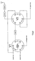
- FIGURES 2A to 2C show another common configuration using two six-ports valves and two separation columns.
- This configuration is often used when the sample matrix, i.e. sample background, is different from the carrier gas.
- the sample background if the sample background reaches the detector, a huge peak will result, masking some of the impurities of interest, and some types of detectors could be damaged by overloading.
- most of the sample background is first "heartcuted" or vented outside the system by the first column. This is achieved by rotating the rotor of valve V1 in the sample injection position to inject a sample, as illustrated in FIGURE 2B .
- valve V2's rotor is rotated to direct the effluent coming out of the first column outside the system, as illustrated in FIGURE 2C .
- the valve V2 is then restored to its original position when most parts of sample background have been vented and before impurities of interest come of the first column.
- the second column which is an analytical column, the impurities will be separated and sequentially introduced in the detector. No detector overload will occur since little or no sample background is present.
- FIGURES 1A to 1D show a typical sample injection rotary valve used in chromatography.
- the fluid flow path is changed by turning the rotor on stator surface.
- FIGURES 1A and 1B show the valve in sampling position while FIGURES 1C and 1D show the valve in sample injection position.
- the sealing action is provided by strongly pressing the rotor on the stator surface.
- the rotor is made of a softer material than the one of the stator.
- the stator is generally polished in order to get a flat surface and minimum roughness.
- Different types of materials have been used for stator and rotor, i.e. metal, ceramic and various polymers.
- metal i.e. aluminum, ceramic and various polymers.
- leaks are much lower than when the fluid is gaseous, even for the same operating pressure.
- Molecule sizes are much bigger and their shapes much more complex for liquids than gases.
- the operating pressure is much lower and most of the time below 300 psig and typically 100 to 150 psig.
- the carrier or sample is H 2 or He, a good sealing is extremely difficult to achieve.
- the diameter of a He molecule is about 0.26 nm.
- the smallest scratch on the stator or rotor surface resulting from surface finish imperfection will cause leaks from port to port.
- the surface finish can be seen as a network of grooves with a random distribution. This makes it difficult to get good sealing for long periods of time.
- analytical methods and systems in which such valve is used are more efficient. This means that the total analytical cycle time has been cut in some cases by a factor of ten. The valves are therefore actuated much more often, their lifetime is then reduced and frequent maintenance is required. As reported in U.S. patent No. 6,453,946 , such maintenance was previously required every six months, but it may now be required every week. Equipment downtime is undesirable.
- stator and rotor In rotary valves used in prior art, there is a fixed and a movable part, commonly known as stator and rotor.
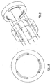
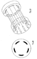
- stator and rotor An example of such assembly is shown in FIGURES 3A to 3D .
- the rotor has some channels therein to allow for various gas connections of stator ports.
- the change in fluid flow path is done by turning the rotor on the stator surface.
- the rotation movement changes the rotor channels position seen by stator's ports.
- different flow paths can be achieved by changing channels configuration in the rotor and the number of ports in the stator.
- FIGURES 4A to 4D there is shown two configurations for 10 and 12-ports valves respectively.
- FIGURES 5A and 5B show a configuration for sample stream selection. These configurations are not limitative or exclusive and many others could be done.
- FIGURES 6A and 6B there are some valves that have a conical shape, as shown in FIGURES 6A and 6B , or a spherical shape, but they all suffer from the same problems.
- the conical valve concept shown in FIGURES 6A and 6B is largely used in most laboratory chromatographs. This valve is manufactured by the Valco Company and U.S. patent No. 4,222,412 illustrates such a valve.
- An object of the present invention is to provide a rotary valve that satisfies the above-mentioned needs.
- the present invention provides a rotary valve provided with a stator having a stator interface and a plurality of fluid open-ports, each of the ports having an opening lying at the stator interface.
- the rotary valve is also provided with a rotor coaxial to the stator and rotatable about an axis with respect to the stator between each of a plurality of rotor positions.
- the rotor has a rotor interface lying against the stator interface.
- the rotor is also provided with at least one fluid channel having an opening extending in the rotor interface for operatively interacting with the fluid open-ports of the stator.
- the rotary valve is also provided with a fluid circulation line comprising a looped recessed fluid circuit extending in the rotor interface.
- the looped fluid circuit has an outer annular recess and an inner recess, each extending in the rotor interface.
- the fluid circuit further has a plurality of separation recesses radially extending in the rotor interface. Each of the separation recesses is connected to each of the inner and outer recesses for defining a plurality of rotor interface portions isolated from each others. Each of the rotor interface portions encloses at the most one of the fluid channels.
- the fluid circulation line is also provided with a fluid inlet and a fluid outlet, each having an opening lying at the stator interface. Each of the inlet and outlet is in continuous fluid communication with a respective one of the inner and outer recesses for providing a continuous fluid flow in the looped recessed fluid circuit.
- Each of the fluid channels extends in a respective one of the rotor interface portions.
- Each of the fluid channels is particularly shaped for connecting two adjacent ports when the rotor is in one of the rotor positions, thereby providing a fluid flow path between the two adjacent ports in said position.
- the ports are circularly arranged in a port circle concentrical with the stator interface between the inner and outer recesses of the rotor and each of the fluid channels extends in the rotor interface in a curve coincidentally with the port circle.
- the inner recess has an annular portion defining a central rotor interface portion therein.
- the ports are particularly arranged so that at anyone of the rotor positions one of the ports is aligned with one of the rotor interface portions.
- the fluid channel has first and second openings extending in the rotor interface. The first opening extends in the central rotor interface portion and provides a continuous fluid communication with a corresponding port aligned therewith. The second opening extends in one of the remaining rotor interface portions and provides a fluid communication with a corresponding port aligned therewith for a given rotor position, thereby providing a fluid flow path between the two ports in simultaneous fluid communication with the first and second openings.
- one of the ports is aligned with the central rotor interface portion.
- the remaining ports are arranged in pairs of first and second ports, each of the pairs being aligned with one of the rotor interface portions.
- the fluid channel has first and second openings extending in the rotor interface.
- the first opening extends in the central rotor interface portion and provides a continuous fluid communication with the corresponding port aligned therewith.
- the second opening extends in one of the remaining rotor interface portions and provides a fluid communication with one port of a corresponding pair aligned therewith for a given rotor position, thereby providing a fluid flow path between the two ports in simultaneous fluid communication with the first and second openings.
- the rotor is further provided with a plurality of recessed grooves.
- Each of the recessed grooves extends in a respective one of the remaining rotor interface portions for respectively connecting each port of a corresponding pair together in one of the rotor positions, thereby providing a vented fluid flow path between each port of the corresponding pair.
- the rotary valve of the present invention prevents cross-port leaks and allows to cancel the effect of any possible leaks by evacuating them. Furthermore, the sweeping action of the rotor's -separation recesses and the corresponding flowing fluid advantageously eliminate the build up and the possibilities of particles trapping that will otherwise dramatically damage the rotor and stator surface. The sweeping fluid in the rotor's separation recesses advantageously provide a self cleaning action. The present rotary valve also presents an improved lifetime.
- the present invention relates to a rotary valve for injecting sample fluid into a flowing fluid or to individually select process fluids from a plurality of process sample points. It could also be used for multi-function fluid and flow path for gas chromatography.
- the present invention provides a multi-port and a multi-positions rotary valve and a method that can be used for sample stream selections, sample injection or multi-function valves used in analytical systems or in industrial application like hydraulic and pneumatic systems.
- the expression "fluid” is intended to cover any fluid such as gas or liquid.
- the rotary valve of the present invention is intended to be used in gas analytical system or in liquid analytical systems.
- the present invention alleviates the most glaring problems of the prior art in providing an improved rotary valve having the following characteristics: there are no dead volumes nor cross-port leaks.
- the valve is inert in that there is no adsorption nor out-gassing.
- the rotary valve is operable under vacuum up to many thousand psi.
- the rotary valve is also operable at high temperatures and prevents inboard and outboard leaks.
- the rotary valve advantageously has a self cleaning action.
- the rotary valve has a long lifetime, i.e. three years and more, even in continuous use.
- the present rotary valve does not rely on elastomer or O-ring type seals in the critical fluid flow path.
- the present rotary valve can advantageously be used in an analytical chromotographic system which is self-diagnostic, so end of life of the valve could be determined in real time.
- the present invention provides an alternative method that can be used to retrofit existing designs and makes them last longer with the pre-cited characteristics.
- the heart of the method is based on the addition of extra recesses in the rotor and extra ports in the stator. These recesses allow to cancel the effect of any possible leaks by evacuating them. They also evacuate particles build up.
- the materials used for the manufacturing of the rotor and stator provide a good inertness and high temperature capability.
- the shape of the recess edge and material used for rotor and stator advantageously provide the long mechanical life.
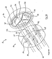
- the rotary valve 20 comprises a stator 22 having a stator interface 24 and a plurality of fluid open-ports 26. Each of the ports 26 has an opening 28 lying at the stator interface 24.
- the rotary valve is also provided with a rotor 30 coaxial to the stator 22 and rotatable about an axis with respect to the stator 22 between each of a plurality of rotor positions.
- the rotor 30 has a rotor interface 32 lying against the stator interface 24 and at least one fluid channel 34 provided with an opening 36 extending in the rotor interface 32 for operatively interacting with the fluid open-ports 26 of the stator 22.
- each of the stator interface 24 and rotor interface 32 has a planar shape. However, these interfaces could also be conically or spherically shaped. These interfaces could also have any convenient shape as known in the art.
- the rotary valve 20 is also provided with a fluid circulation line having a looped recessed fluid circuit 38 extending in the rotor interface 32.
- the looped fluid circuit 38 has an outer annular recess 40 and an inner recess 42, each extending in the rotor interface 32.
- the fluid circuit 38 further has a plurality of separation recesses 44 radially extending in the rotor interface 32. Each of the separation recesses 44 is connected to each of the inner and outer recesses 42, 40 for defining a plurality of rotor interface portions 46 isolated from each others.
- Each of the rotor interface portions 46 encloses at the most one of the fluid channels 34. It is understood by this that any given rotor interface portion may enclose an entire fluid channel, a portion of such a channel or none at all. However, no part of two different channels can be found within a single rotor interface portion; in this manner, the boundaries of the rotor interface portions will provide a barrier against cross-contamination between the different channels.
- the fluid circulation line is also provided with a fluid inlet 48 and a fluid outlet 50, each having an opening 52 lying at the stator interface 24.
- Each of the inlet and outlet 48, 50 is in continuous fluid communication with a respective one of the inner and outer recesses 42, 40 for providing a continuous fluid flow in the looped recessed fluid circuit 38.
- the inner recess 42 has a round shape diametrically corresponding to the opening 52 of a respective one of the fluid inlet and outlet 48, 50.
- each of the three fluid channels 34 extends in a respective one of the three rotor interface portions 46.
- Each of the fluid channels 34 is particularly shaped for connecting two adjacent ports 26 when the rotor 30 is in one of the rotor positions, thereby providing a fluid flow path between the two adjacent ports 26 in said position.
- the ports 26 are circularly arranged in a port circle concentrical with the stator interface 24 between the inner and outer recesses 42, 40 of the rotor 30.
- Each of the fluid channels 34 extends in the rotor interface 32 in a curve coincidental with the port circle.
- each of the fluid channels 34 preferably has its opening 36 opened lengthwise in the rotor interface 32 for precisely linking the two adjacent ports 26.
- each of the fluid channels 34 could also extends inside the rotor 30 and be provided with first and second openings extending in the rotor interface 32, each being aligned with the respective port 26 for linking the two adjacent ports 26.
- the fluid open-ports 26 of the valve 20 provide a carrier gas circuit and a sample gas one connected to and passing through the valve 20, like any other conventional sample injection six-port valve system. It should be understood that any convenient number of ports 26 could also be envisaged for a specific application.
- the continuous fluid flow in the looped recessed fluid circuit 38 provides an extra gas circuit into the valve 20.
- Carrier gas is introduced at the inlet 48, sweeping the outer annular recess 40 and separation recesses 44, and then exiting the valve 20 at the outlet 50.
- the positions of the inlet 48 and the outlet 50 may be interchanged.
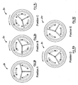
- valve When the valve needs to be rotated or actuated, this is done in the same way as the other six-port rotary valves, i.e. by rotating the rotor 30 on the stator 22, as illustrated in FIGURES 8A to 8E .
- each of the separation recesses 44 preferably extends at a predetermined position so that at most one of the ports 26 is in fluid communication with the looped fluid circuit 38 for any relative orientation of the rotor 30 with respect to the stator 22, as can be shown in FIGURE 7D . This prevents a short circuit or a connection between stator critical ports 26, which is particularly advantageous in cases where cross-contamination between different parts could lead to an explosive or otherwise dangerous reaction.
- any leak from any of the three pairs of ports 26 will reach one of the separation recesses 44 and will be carried away from the valve 20 by the pure carrier sweeping gas of the circulation line. This way, the leak is evacuated from the valve 20 without interfering with the process of impurities identification and quantification or other primary function of the valve.
- the separation recesses 44 allow to eliminate the effect of any cross-port leak that could appear over the time because of wearing of the rotor or stator interfaces 24, 32.
- the outer annular recess 40 prevents any inboard or outboard leaks from the valve 20. If it happens, the outboard and inboard leaks are evacuated out of the valve 20 and do not reach critical analytical flow path.
- the outer annular recess 40 acts as an active seal. Thus, it seals and evacuates leaks at the same time.
- the rotary valve is preferably provided with a sealed housing for sealably enclosing the rotor 30 and the stator 22 therein.
- the housing is purged by the carrier gas. Thus, it isolates completely the valve's critical analytical flow path from its environment.
- the rotor 30 and the stator 22 are preferably made of ultra hard ceramic, such as for example Alumina or Zirconia.
- the rotor and stator interfaces 32, 24 are preferably polished so well that just the fact of putting the rotor 30 on the stator 22 evacuates ambient air between both faces and creates a vacuum.
- these interfaces 34, 32 could be coated with various materials acting as lubricants for increasing the quality of the surface. The type of coating to be used depends of which operating conditions the valves will be used in, i.e. temperature and type of fluid. These parameters are well known from people involved in the art and will not be further described therein.
- each of the fluid open-ports 26 of the stator 22 preferably has a down sloped edge or a round shape.
- the opening 36 of the fluid channel 34 also preferably has a down sloped edge or a round shape.
- Each of the inner recess 42, outer recess 40 and separation recesses 44 is also advantageously provided with a down sloped edge or a round shape. This eliminates the "razor blade" effect of these edges on the interfaces 24, 32 when rotor interface 32 rotates on the stator interface 24. This avoids the build-up of scratches on the interfaces that cause excessive wearing and consequently leaks.
- each of the separation recesses 44 can advantageously be provided with a fin extending on an edge thereof for increasing the mechanical sweeping effect.
- the fins are advantageously made of teflon but any other soft and non-absorbent material could also be envisaged. It could also be envisaged to provide a fin on each opposed edge of each of the separation recesses 44 or to provide a single fin on one of the separation recesses 44.
- the stator has a metallic base element and a ceramic element providing the stator interface 24.
- the ceramic element is placed on a metallic base element to provide long life expectancy.
- Each of the stator elements are sealed together with the ceramic element and metallic base element having aligned passages.
- drawbacks to such assembly as described in U.S. patent No. 6,453,946 . More particularly, there is volume added to the valve causing dispersion and the risk of leaks at high temperature.
- Such valves are manufactured under model #7750E-020 from Rheodyne L.P.
- the fluid tubings are brazed to the ceramic element of the stator. This brazing is done under vacuum and provides a dead volume free and leak tight joint.
- the ceramic stator tubing assemblies are mounted to the base of the valve housing by passing the tubing to their corresponding ports in the valve base until the ceramic element comes seated on the plane surface of the valve base.
- the stator 22 is also provided with a set of holding pins, three for example, having tight tolerances. These pins allow to maintain and align the ceramic element on the valve base. The holding pins prevent any rotation of the stator 22 due to the rotating movement of the rotor 30 and maintain a precise alignment of the stator ports 26 relative to the rotor's channels 34.
- the rotary valve is also provided with an actuation mechanism operatively connected to the rotor 30 for actuating the rotor in a desired one of the rotor positions.
- the rotor 30 is then attached to the actuation mechanism and aligned with the stator 22 at the proper and precise angle.
- Each of the fluid channels 34 preferably links precisely two of the stator ports 26.
- the valve cover and the metal gasket at its base are mounted on the valve base and properly tightened.
- the rotor shaft extends the valve cover. Any length of actuation shaft could be fitted in the case that the valve is installed in an oven. This way the actuation mechanism could be at ambient temperature.
- Actuation mechanism could be an electrical motor, solenoid, pneumatic, or simply a handle turned by hand.
- the rotor 30 and the stator 22 are advantageously made of ultra-hard material, i.e. ceramic (Alumina or Zirconia).
- the rotor and stator recesses and ports preferably have a smooth round edge instead of a sharp edge.
- the rotor and stator interfaces 32, 24 are advantageously highly polished and have a lubricant coating compatible with the application.
- the stator tubings are preferably brazed thereon.
- the stator 22 and the rotor 30 are advantageously mounted in a sealed housing and purged by the carrier gas.
- the separation recesses 44 are done at proper angle from each other in order to have only one separation recess 44 passing over a stator port 26 at a time.
- a valve is advantageously used in a chromatographic system.
- the carrier gas and sample gas are connected in a conventional way.
- This carrier gas sweeps the outer annular recess 40 and the separation recesses 44, and then exits at the stator's fluid outlet 50.
- the valve 20 is advantageously provided with the sealed housing purged by the carrier gas. With these characteristics, an extremely high performance valve is obtained.
- Such a valve is inert, dead volume free, and unaffected by leak developed over a long period of time. The lifetime of this valve becomes very long in comparison with the valves known in the art.
- the present invention also provides an analytical chromatographic system 54 using the rotary valve 20 previously described.
- Such an analytical system 54 is provided with monitoring means operatively connected to the fluid outlet 50 for monitoring a fluid passing therethrough.
- the monitoring means comprises a purity detector 56 for detecting contamination of said fluid.
- the fluid outlet 50 of the stator 22 is connected to the purity detector 56.
- the purity detector 56 is reading in a synchronised manner, i.e. there is some delay before the actuation to avoid to read the normal "sample pulse" when one separation recess 44 passes over the sample port 26. It also appears that the separation recesses 44 not only eliminate the effect of internal leaks, and this at various operating pressures, but also have a kind of cleaning effect.
- the concept of the present invention can also be very useful in other valve's port arrangements for other applications.
- an important function in analytical systems is to measure some impurities in various sample streams. So it is required to sequentially select those various sample streams. A sample stream selector valve is then required.
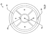
- FIGURES 9A and 9B show a first preferred embodiment of the valve 20 of the present invention used in such application.
- This embodiment illustrates a four sample streams selection valve, but it should be understand that it is not limited to four and that it could be extended to more sample channels.
- the inner recess 42 has an annular portion defining a central rotor interface portion 58 therein.
- the ports 26 are particularly arranged so that at anyone of the rotor positions, one of the ports 26 is aligned with one of the rotor interface portions 46, 58.
- the fluid channel 34 is provided with first and second openings 60, 62 extending in the rotor interface 32.
- the first opening 60 extends in the central rotor interface portion 58 and provides a continuous fluid communication with a corresponding port 26 aligned therewith.
- the second opening 62 extends in one of the remaining rotor interface portions 46 and provides a fluid communication with a corresponding port 26 aligned therewith for a given rotor position, thereby providing a fluid flow path between the two ports 26 in simultaneous fluid communication with the first and second openings 60, 62.
- the ports 26 aligned with the remaining rotor interface portions 44 are preferably circularly arranged on a port circle concentrical with the rotor interface 32 between the inner and outer recesses 42, 40 of the rotor 30.
- This valve 20 can also advantageously be mounted in a purge housing, similarly to the injection valve previously described.
- the sample stream is selected by turning the rotor 30 over the stator 22.
- the inner and outer recesses 42, 40 and the separation recesses 44 are purged with a clean and high purity gas. This purging could be at positive pressure or under vacuum. The object of this purging is again to evacuate any leak that may contaminate the selected sample outside the valve 20. Inboard and outboard contaminations are eliminated by the outer annular recess 40 and the purge housing enclosing the valve.
- valve 20 shown in FIGURES 9A and 9B is of high value since user can be sure of the system integrity. The sample is not contaminated by the sample stream selection system.
- valves of the present invention could also be combined in an analytical system.
- Each of the valves could be provided with its own purity detector 56.
- a single purity detector 56 connected to the sample steams selection valve could be used for monitoring the fluid passing through each of the valves. This particular arrangement would allow to detect contamination of each of the fluids without dramatically increasing the cost of the system.
- FIGURE 10 Another advantageous variation of a sample stream selection based on this method is illustrated in FIGURE 10 .
- the unselected samples are bypassed to keep a constant flow and are individually vented outside the system. This is very useful when the various samples are not the same type and then, not compatible.
- one of the ports 26 is aligned with the central rotor interface portion 58.
- the remaining ports 26 are preferably arranged in pairs 64 of first and second ports. Each of the pairs 64 is aligned with one of the rotor interface portions 46 for a given position.
- the fluid channel 34 has first and second openings 60, 62 extending in the rotor interface 32.
- the first opening 60 extends in the central rotor interface portion 58 and provides a continuous fluid communication with the corresponding port 26 aligned therewith.
- the second opening 62 extends in one of the remaining rotor interface portions 46 and provides a fluid communication with one port 26 of a corresponding pair 64 aligned therewith for a given rotor position, thereby providing a fluid flow path between the two ports 26 in simultaneous fluid communication with the first and second openings 60, 62.
- the rotor 30 is further advantageously provided with a plurality of recessed grooves 66, each of the recessed grooves 66 extending in a respective one of the remaining rotor interface portions 46 for respectively connecting each port 26 of a corresponding pair 64 together in one of the rotor positions, thereby providing a vent fluid flow path between each port 26 of the corresponding pair 64.
- each first port of each of the pairs 64 is circularly arranged on a first port circle concentrical with the rotor interface 32.
- Each second port of each of the pairs 64 is preferably circularly arranged on a second circle concentrical with the rotor interface 32.
- any other convenient arrangement of the ports 26 could also be envisaged according to a particular application.
- FIGURES 12A and 12B illustrate another preferred embodiment of the present invention.
- This embodiment shows a conical valve like the ones made by Valco Company, but manufactured according to the concept of the present invention.
- This valve 20 has also been tested in laboratory and has demonstrated an excellent performance with Helium as carrier gas. Lifetime expectancy has been proven to be at least three times longer than with the unmodified version. This is a real improvement for many systems installed in the field.
Landscapes
- Physics & Mathematics (AREA)
- Health & Medical Sciences (AREA)
- Life Sciences & Earth Sciences (AREA)
- Chemical & Material Sciences (AREA)
- Analytical Chemistry (AREA)
- Biochemistry (AREA)
- General Health & Medical Sciences (AREA)
- General Physics & Mathematics (AREA)
- Immunology (AREA)
- Pathology (AREA)
- Engineering & Computer Science (AREA)
- General Engineering & Computer Science (AREA)
- Mechanical Engineering (AREA)
- Multiple-Way Valves (AREA)
- Sampling And Sample Adjustment (AREA)
Claims (21)
- Soupape rotative (20) comprenant :un stator (22) ayant une interface de stator (24) et une pluralité d'orifices ouverts (26) de fluide, chacun desdits orifices (26) ayant une ouverture (28) se trouvant au niveau de ladite interface de stator (24) ;un rotor (30) coaxial par rapport audit stator (22) et pouvant tourner autour d'un axe par rapport audit stator (22) entre chacune d'une pluralité de positions de rotor, ledit rotor (30) ayant une interface de rotor (32) se trouvant contre ladite interface de stator (24) et au moins un canal de fluide (34) prévu avec une ouverture (36) s'étendant dans ladite interface de rotor (32) pour interagir de manière opérationnelle avec les orifices ouverts (26) de fluide du stator (22) ; etune conduite de circulation de fluide comprenant :un circuit de fluide évidé en boucle (38) s'étendant dans ladite interface de rotor (32), ledit circuit de fluide en boucle (38) comprenant un évidement annulaire externe (40) et un évidement interne (42), chacun s'étendant dans ladite interface de rotor (32), ledit circuit de fluide (38) comprenant en outre une pluralité d'évidements de séparation (44) s'étendant radialement dans ladite interface de rotor (32), chacun desdits évidements de séparation (44) étant raccordé à chacun desdits évidements interne (42) et externe (40) pour définir une pluralité de parties d'interface de rotor (46) isolées les unes par rapport aux autres, chacune desdites parties d'interface de rotor (46) enfermant au maximum un des canaux de fluide (34) ; etune entrée de fluide (48) et une sortie de fluide (50), ayant chacune une ouverture (52) se trouvant au niveau de ladite interface de stator (24), chacune parmi ladite entrée (48) et ladite sortie (50) étant en communication de fluide continue avec un évidement respectif desdits évidements interne (42) et externe (40) pour fournir un écoulement de fluide continu dans ledit circuit de fluide évidé en boucle (38) ;caractérisée en ce que chacun desdits canaux de fluide (34) s'étend dans une partie respective desdites parties d'interface de rotor (46), chacun desdits canaux de fluide (34) étant formé de manière particulière pour raccorder deux orifices (26) adjacents lorsque ledit rotor (30) est dans l'une desdites positions de rotor, fournissant ainsi une trajectoire d'écoulement de fluide entre lesdits deux orifices (26) adjacents dans ladite position, et en ce que lesdits orifices (26) sont agencés de manière circulaire dans un cercle d'orifice concentrique par rapport à ladite interface de stator (24) entre lesdits évidements interne (42) et externe (40) dudit rotor (30), chacun desdits canaux de fluide (34) s'étendant dans ladite interface de rotor (32) dans une courbe qui coïncide avec ledit cercle d'orifice.
- Soupape rotative (20) selon la revendication 1, dans laquelle chacun desdits évidements de séparation (44) s'étend dans une position prédéterminée de sorte qu'au maximum l'un desdits orifices (26) est en communication de fluide avec ledit circuit de fluide en boucle (38) pour n'importe quelle orientation relative du rotor (30) par rapport au stator (22).
- Soupape rotative (20) selon la revendication 1, dans laquelle ledit évidement interne (42) a une forme ronde correspondant diamétralement à l'ouverture (52) d'une entrée et d'une sortie respective de ladite entrée de fluide (48) et de ladite sortie (50).
- Soupape rotative (20) selon la revendication 1, dans laquelle ledit évidement interne (42) comprend une partie annulaire définissant une partie d'interface de rotor centrale (58) à l'intérieur de cette dernière.
- Soupape rotative (20) selon la revendication 4, dans laquelle lesdits évidements (26) sont agencés de manière particulière de sorte qu'à l'une quelconque desdites positions de rotor, l'un desdits orifices (26) est aligné avec l'une desdites parties d'interface de rotor (46, 58).
- Soupape rotative (20) selon la revendication 4, dans laquelle l'un desdits orifices (26) est agencé avec ladite partie d'interface de rotor centrale (58), les orifices résiduels (26) étant agencés en paires (64) de premier et deuxième orifices, chacune desdites paires (64) étant alignée avec l'une desdites parties d'interface de rotor (46) pour une position donnée, ledit canal de fluide (34) comprenant des première (60) et deuxième (62) ouvertures s'étendant dans ladite interface de rotor (32), la première ouverture (60) s'étendant dans ladite partie d'interface de rotor centrale (58) et fournissant une communication de fluide continue avec l'orifice (26) correspondant aligné avec cette dernière, la deuxième ouverture (62) s'étendant dans l'une des parties d'interface de rotor résiduelles (46) et fournissant une communication de fluide avec un orifice (26) d'une paire (64) correspondante alignée avec cette dernière pour une position de rotor donnée, fournissant ainsi une trajectoire d'écoulement de fluide entre les deux orifices (26) en communication de fluide simultanée avec lesdites première (60) et deuxième (62) ouvertures, ledit rotor (30) comprenant en outre une pluralité de rainures évidées (66), chacune desdites rainures évidées (66) s'étendant dans une partie respective desdites parties d'interface de rotor résiduelles (46) pour raccorder respectivement chaque orifice (26) d'une paire (64) correspondante ensemble dans l'une desdites positions de rotor, fournissant ainsi une trajectoire d'écoulement de fluide d'évacuation entre chaque orifice (26) de la paire (64) correspondante.
- Soupape rotative (20) selon la revendication 6, dans laquelle chaque premier orifice de chacune desdites paires (64) est agencé de manière circulaire sur un premier cercle d'orifice concentrique avec ladite interface de rotor (32), chaque deuxième orifice de chacune desdites paires (64) étant agencé de manière circulaire sur un deuxième cercle concentrique avec ladite interface de rotor (32).
- Soupape rotative (20) selon la revendication 1, dans laquelle chacune parmi ladite interface de stator (24) et ladite interface de rotor (32) a une forme plane.
- Soupape rotative (20) selon la revendication 1, dans laquelle chacune de ladite interface de stator (24) et ladite interface de rotor (32) a une forme conique.
- Soupape rotative (20) selon la revendication 1, dans laquelle chacune de ladite interface de stator (24) et de ladite interface de rotor (32) a une forme sphérique.
- Soupape rotative (20) selon la revendication 1, dans laquelle l'ouverture (36) de chacun desdits orifices ouverts (26) de fluide a un bord lisse incliné.
- Soupape rotative (20) selon la revendication 1, dans laquelle l'ouverture (36) dudit canal de fluide (34) a un bord lisse incliné.
- Soupape rotative (20) selon la revendication 1, dans laquelle chacun parmi ledit évidement interne (42), ledit évidement externe (40) et lesdits évidements de séparation (44) a un bord lisse incliné.
- Soupape rotative (20) selon la revendication 1, dans laquelle ladite soupape rotative (20) comprend en outre un mécanisme d'actionnement raccordé de manière opérationnelle audit rotor (30) pour actionner ledit rotor dans une position souhaitée desdites positions de rotor.
- Soupape rotative (20) selon la revendication 1, dans laquelle ladite soupape rotative (20) comprend en outre un boîtier étanche pour enfermer hermétiquement le rotor (30) et le stator (22) à l'intérieur de ce dernier, ledit boîtier étant purgé par un fluide.
- Soupape rotative (20) selon la revendication 1, dans laquelle chacun parmi le stator (22) et le rotor (30) est réalisé à partir d'une céramique ultra-dure.
- Soupape rotative (20) selon la revendication 1, dans laquelle chacune parmi l'interface de stator (24) et l'interface de rotor (32) est polie.
- Soupape rotative (20) selon la revendication 1, dans laquelle chacune parmi l'interface de stator (24) et l'interface de rotor (32) a un revêtement.
- Soupape rotative (20) selon la revendication 1, dans laquelle ledit stator (22) comprend un élément de céramique fournissant ladite interface de stator (24), ledit stator (22) comprenant en outre un élément de base métallique et une pluralité de tubes de fluide fournissant les orifices ouverts (26) de fluide, lesdits tubes de fluide étant brasés sur l'élément en céramique.
- Soupape rotative (20) selon la revendication 19, dans laquelle ledit stator (22) comprend en outre un ensemble de broches de support s'étendant à l'intérieur de ce dernier pour maintenir et positionner l'élément en céramique et l'élément de base métallique, ensemble.
- Soupape rotative (20) selon la revendication 1, dans laquelle ladite soupape rotative (20) comprend en outre au moins une ailette, chacune desdites ailettes s'étendant sur un bord de l'un des évidements de séparation (44).
Applications Claiming Priority (1)
| Application Number | Priority Date | Filing Date | Title |
|---|---|---|---|
| PCT/CA2004/001560 WO2006021071A1 (fr) | 2004-08-25 | 2004-08-25 | Soupape rotative et systeme chromatique d'analyse utilisant cette soupape rotative |
Publications (3)
| Publication Number | Publication Date |
|---|---|
| EP1789708A1 EP1789708A1 (fr) | 2007-05-30 |
| EP1789708A4 EP1789708A4 (fr) | 2010-03-10 |
| EP1789708B1 true EP1789708B1 (fr) | 2011-10-19 |
Family
ID=35967138
Family Applications (1)
| Application Number | Title | Priority Date | Filing Date |
|---|---|---|---|
| EP20040761724 Expired - Lifetime EP1789708B1 (fr) | 2004-08-25 | 2004-08-25 | Soupape rotative et systeme chromatique d'analyse utilisant cette soupape rotative |
Country Status (6)
| Country | Link |
|---|---|
| US (1) | US7503203B2 (fr) |
| EP (1) | EP1789708B1 (fr) |
| CN (1) | CN101044346B (fr) |
| AT (1) | ATE529671T1 (fr) |
| CA (1) | CA2577824C (fr) |
| WO (1) | WO2006021071A1 (fr) |
Cited By (2)
| Publication number | Priority date | Publication date | Assignee | Title |
|---|---|---|---|---|
| US12297931B2 (en) | 2021-02-08 | 2025-05-13 | Schivo Medical Limited | Centering electronic rotary valve |
| US12402773B2 (en) | 2023-08-29 | 2025-09-02 | Haier Us Appliance Solutions, Inc. | Multichannel dispenser assembly |
Families Citing this family (70)
| Publication number | Priority date | Publication date | Assignee | Title |
|---|---|---|---|---|
| US8881582B2 (en) | 2005-01-31 | 2014-11-11 | Waters Technologies Corporation | Method and apparatus for sample injection in liquid chromatography |
| US8047060B2 (en) * | 2005-01-31 | 2011-11-01 | Waters Technologies Corporation | Method and apparatus for sample injection in liquid chromatography |
| CN100453867C (zh) * | 2007-01-19 | 2009-01-21 | 西安交通大学 | 一种用于高效液相制备色谱模拟移动床的36通旋转阀 |
| CA2676169A1 (fr) * | 2007-02-22 | 2008-08-28 | Ge Healthcare Bio-Sciences Ab | Vanne de selection rotative |
| EP2147302A1 (fr) * | 2007-05-15 | 2010-01-27 | GE Healthcare Bio-Sciences AB | Vanne rotative à accès aléatoire |
| WO2009006742A1 (fr) * | 2007-07-10 | 2009-01-15 | Mécanique Analytique Inc. | Robinet à membrane comportant des orifices de communication intermédiaires |
| JP4862947B2 (ja) * | 2007-09-28 | 2012-01-25 | 株式会社島津製作所 | 試料導入装置 |
| DE102007059651B4 (de) * | 2007-12-10 | 2017-05-24 | Dionex Softron Gmbh | Probengeber für die Hochleistungsflüssigkeitschromatographie |
| CN101939575B (zh) * | 2007-12-12 | 2012-02-08 | 机械解析有限公司 | 带有过程清洗槽的隔膜密封阀 |
| US8250904B2 (en) | 2007-12-20 | 2012-08-28 | Schlumberger Technology Corporation | Multi-stage injector for fluid analysis |
| DE102008006266B4 (de) | 2008-01-25 | 2011-06-09 | Dionex Softron Gmbh | Probengeber für die Flüssigkeitschromatographie, insbesondere für die Hochleistungsflüssigkeitschromatographie |
| US20100276617A1 (en) * | 2008-02-14 | 2010-11-04 | Shimadzu Corporation | Flow channel switching valve |
| EP2245448A2 (fr) * | 2008-02-28 | 2010-11-03 | Services Pétroliers Schlumberger | Injecteur multi-étage pour analyse de fluide |
| US20090320925A1 (en) * | 2008-06-25 | 2009-12-31 | Rheodyne, Llc | Rotor element for a shear valve with subterranean passage and method |
| DE102009005874A1 (de) * | 2009-01-21 | 2010-07-22 | Thinxxs Microtechnology Ag | Ventil, insbesondere für ein Bauelement der Mikrofluidtechnik |
| US9285035B2 (en) | 2009-03-17 | 2016-03-15 | Danfoss A/S | Valve for a vapour compression system |
| EP2445602A4 (fr) * | 2009-06-26 | 2013-11-13 | Waters Technologies Corp | Appareil de chromatographie ayant un c ur intégré |
| WO2011001460A1 (fr) * | 2009-06-29 | 2011-01-06 | 株式会社島津製作所 | Soupape de commande de voie d'écoulement |
| WO2011072685A1 (fr) * | 2009-12-18 | 2011-06-23 | Danfoss A/S | Unité de dispositif de dilatation pour un système de compression de vapeur |
| US8656955B2 (en) | 2010-05-20 | 2014-02-25 | Bio-Rad Laboratories, Inc. | Rotary column selector valve |
| US8627851B2 (en) * | 2010-06-14 | 2014-01-14 | Idex Health & Science Llc | Rebuildable micro-fluidic valve assembly |
| US20120145937A1 (en) * | 2010-12-13 | 2012-06-14 | Richman Bruce A | Rotary valve for sample handling in fluid analysis |
| DE102011000104B4 (de) * | 2011-01-12 | 2013-02-07 | Dionex Softron Gmbh | Hochdruck-Schaltventil für die Hochleistungsflüssigkeitschromatographie |
| US9435775B2 (en) | 2011-02-07 | 2016-09-06 | Waters Technologies Corporation | Fluid switching valve |
| US8960231B2 (en) | 2011-09-21 | 2015-02-24 | Neil Robert Picha | Multi-mode injection valve |
| WO2013059253A1 (fr) * | 2011-10-20 | 2013-04-25 | Rosemount Alalytical, Inc. | Instrument analytique de traitement ayant une liaison multitubes |
| US8813785B2 (en) * | 2012-01-09 | 2014-08-26 | Promochrom Technologies Ltd. | Fluid selection valve |
| DE102012005270A1 (de) * | 2012-03-10 | 2013-09-12 | Microfluidic Chipshop Gmbh | Vorrichtung zur Manipulation von Flüssigkeiten |
| WO2013191879A2 (fr) * | 2012-06-19 | 2013-12-27 | Waters Technologies Corporation | Rotors moulés par injection-compression |
| EP2807410B1 (fr) | 2012-07-17 | 2017-08-30 | Idex Health & Science LLC | Methode de transfert d'un échantillon liquide au moyen d'une vanne d'échantillonage |
| US9435440B2 (en) | 2012-08-06 | 2016-09-06 | Mécanique Analytique Inc. | Valve with a loading varying mechanism, and method of operating the same |
| US10254255B2 (en) | 2012-09-20 | 2019-04-09 | Waters Technologies Corporation | Rotary selector valve and associated systems and methods |
| US9410976B2 (en) | 2012-10-17 | 2016-08-09 | Rosemount Analytical Inc. | Process analytic instrument with encapsulated flame-quenching connection |
| CN103134876B (zh) * | 2012-12-29 | 2015-04-08 | 聚光科技(杭州)股份有限公司 | 色谱分析装置及其工作方法 |
| CN105339789B (zh) | 2013-03-11 | 2017-03-29 | 机械解析有限公司 | 具有密封组件的隔膜阀、包括隔膜阀的色谱系统及其操作方法 |
| US9841406B2 (en) | 2013-04-22 | 2017-12-12 | Sekisui Medical Co., Ltd. | Switching valve for flow type analysis apparatus |
| US20150107706A1 (en) * | 2013-10-18 | 2015-04-23 | Delavan Inc. | Vortex chamber for fluid control valves |
| JP6437005B2 (ja) | 2014-02-12 | 2018-12-12 | アイデックス ヘルス アンド サイエンス エルエルシー | 多次元液体分析システムにおける体積フローの調整 |
| JP6685274B2 (ja) * | 2014-03-28 | 2020-04-22 | ジーイー・ヘルスケア・バイオサイエンス・アクチボラグ | 連続クロマトグラフィーシステムにおける方法、バルブおよびクロマトグラフィーシステム |
| CN104500785B (zh) * | 2015-01-14 | 2017-02-22 | 上海浦东汉威阀门有限公司 | 24通旋转阀 |
| CN104500784B (zh) * | 2015-01-14 | 2017-02-01 | 上海浦东汉威阀门有限公司 | 24通旋转阀 |
| GB201505421D0 (en) * | 2015-03-30 | 2015-05-13 | Ge Healthcare Bio Sciences Ab | A rotary valve and a chromatography system |
| DE202016100451U1 (de) | 2015-06-25 | 2016-02-16 | Dionex Softron Gmbh | Probengeber für die Flüssigkeitschromatographie, insbesondere für die Hochleistungsflüssigkeitschromatographie |
| DE102016101658B4 (de) | 2016-01-29 | 2018-04-05 | Dionex Softron Gmbh | Probenvorkompressionsventil für die Flüssigkeitschromatographie, insbesondere für die Hochleistungsflüssigkeitschromatographie |
| US11054054B2 (en) | 2016-12-09 | 2021-07-06 | Idex Health & Science Llc | High pressure valve with multi-piece stator assembly |
| US10384151B2 (en) | 2016-12-09 | 2019-08-20 | Idex Health & Science Llc | High pressure valve with two-piece stator assembly |
| CN106763910B (zh) * | 2017-01-22 | 2023-08-11 | 成都赛普瑞兴科技有限公司 | 一种旋转装置及气体分离装置 |
| DE102017101629A1 (de) * | 2017-01-27 | 2018-08-02 | Agilent Technologies, Inc. - A Delaware Corporation - | Fluidventil mit goldhaltiger und/oder platinhaltiger Beschichtung |
| US10487954B2 (en) * | 2017-02-03 | 2019-11-26 | Micromeritics Instrument Corporation | Blend valve |
| CN107355564A (zh) * | 2017-07-10 | 2017-11-17 | 成都赛普瑞兴科技有限公司 | 一种旋转阀及其组件 |
| PL233336B1 (pl) * | 2017-10-26 | 2019-09-30 | Univ Jana Kochanowskiego W Kielcach | Trójpozycyjny sześciodrożny zawór do dozowania próbek adsorbatów, zwłaszcza do inwersyjnej chromatografii gazowej |
| US10527192B2 (en) | 2018-02-15 | 2020-01-07 | Talis Biomedical Corporation | Rotary valve |
| EP3561504B1 (fr) * | 2018-04-25 | 2023-01-04 | Idex Health & Science LLC | Soupape haute pression comportant un ensemble stator multi-pièces |
| WO2019227231A1 (fr) * | 2018-06-01 | 2019-12-05 | Mécanique Analytique Inc. | Soupape de chromatographie destinée à une analyse de fluide |
| US11598431B2 (en) | 2018-11-01 | 2023-03-07 | Idex Health & Science, Llc | Multiple channel selector valve |
| US12007034B2 (en) | 2019-01-22 | 2024-06-11 | Totalenergies Onetech (Previously Totalenergies One Tech) | Injection valve for an analysis apparatus |
| JP7472156B2 (ja) * | 2019-02-20 | 2024-04-22 | エフ ホフマン-ラ ロッシュ アクチェン ゲゼルシャフト | 少なくとも1つの流体を移送するためのバルブ |
| US11008627B2 (en) | 2019-08-15 | 2021-05-18 | Talis Biomedical Corporation | Diagnostic system |
| CN111157662B (zh) * | 2020-02-24 | 2024-07-19 | 苏州英赛斯智能科技有限公司 | 多柱位旋转阀和色谱仪 |
| CN114688301A (zh) * | 2020-12-31 | 2022-07-01 | 深圳市真迈生物科技有限公司 | 流动路径选择阀、流动池组件、液路系统及测序系统 |
| CN114321036A (zh) * | 2020-09-29 | 2022-04-12 | 深圳市真迈生物科技有限公司 | 液路系统、检测系统和应用 |
| US12320441B1 (en) * | 2021-02-08 | 2025-06-03 | Schivo Medical Limited | Centering electronic rotary valve |
| CN115199778A (zh) * | 2021-04-13 | 2022-10-18 | 广东德昌电机有限公司 | 阀门 |
| JP7844493B2 (ja) * | 2021-09-21 | 2026-04-13 | イーグル工業株式会社 | 切換弁 |
| CN114113430B (zh) * | 2021-11-30 | 2025-02-18 | 泰渡生物科技(苏州)有限公司 | 一种层析实验系统及转动阀 |
| CN114518426B (zh) * | 2022-03-03 | 2023-11-03 | 宁波艾纯生物科技有限公司 | 一种进样阀 |
| JP2024162675A (ja) * | 2023-05-11 | 2024-11-21 | 愛三工業株式会社 | 流路切替装置 |
| DE102023119806A1 (de) * | 2023-07-26 | 2025-01-30 | Hochschule Aalen, Körperschaft des öffentlichen Rechts | Vorrichtung zum Transfer einer Flüssigkeitsprobe innerhalb eines mikrofluidischen Systems |
| CN116928391B (zh) * | 2023-09-04 | 2025-11-04 | 龙牌食品股份有限公司 | 一种管道转换系统 |
| WO2025153480A1 (fr) * | 2024-01-15 | 2025-07-24 | F. Hoffmann-La Roche Ag | Détection de fuite de soupape |
Family Cites Families (30)
| Publication number | Priority date | Publication date | Assignee | Title |
|---|---|---|---|---|
| US2519574A (en) * | 1944-02-28 | 1950-08-22 | James W F Holl | Rotary fluid valve |
| DE1171177B (de) * | 1961-08-18 | 1964-05-27 | Bodenseewerk Perkin Elmer Co | Dreiwege-Umschalthahn fuer Gas-chromatographen |
| US3223123A (en) * | 1963-05-27 | 1965-12-14 | Sun Oil Co | Multifunction valve for chromatography |
| US3297053A (en) * | 1963-12-30 | 1967-01-10 | Carle Instr Inc | Selector valve |
| US4068528A (en) * | 1976-01-19 | 1978-01-17 | Rheodyne Incorporated | Two position rotary valve for injecting sample liquids into an analysis system |
| DE2724252C2 (de) * | 1977-05-28 | 1982-12-16 | Hoechst Ag, 6000 Frankfurt | Schlauchförmiges Verpackungsmaterial, vorzugsweise zur Verwendung als Wursthülle |
| US4243071A (en) | 1978-08-23 | 1981-01-06 | Altex Scientific, Inc. | Sample injection valve |
| US4182184A (en) * | 1978-12-14 | 1980-01-08 | Rheodyne Incorporated | Sample injector |
| US4222412A (en) * | 1979-01-15 | 1980-09-16 | Carle Instruments, Inc. | High pressure valve for chromatography |
| US4242909A (en) * | 1979-04-19 | 1981-01-06 | Rheodyne Incorporated | Sample injector |
| DE3037014C2 (de) | 1980-10-01 | 1984-10-18 | Bodenseewerk Perkin-Elmer & Co GmbH, 7770 Überlingen | Verfahren und Probeneinlaßventil zum Aufgeben von Proben bei der Flüssigchromatographie |
| US4383726A (en) * | 1980-12-22 | 1983-05-17 | Carrier Corporation | Electric terminal |
| US4476731A (en) * | 1983-03-03 | 1984-10-16 | Scientific Systems, Inc. | Injection valve for liquid chromatographic column and system therefor |
| US4506558A (en) * | 1983-03-03 | 1985-03-26 | Rheodyne Incorporated | Injector with minimal flow-interrupt transient |
| CH674580A5 (fr) * | 1983-10-06 | 1990-06-15 | Contraves Ag | |
| US4577515A (en) * | 1984-06-19 | 1986-03-25 | Tokyo Rika Kikai Co., Ltd. | Sampling valve for use in high-speed liquid chromatography |
| US4702889A (en) * | 1986-01-16 | 1987-10-27 | Coulter Electronics Inc. | Liquid sampling valve |
| US5207109A (en) * | 1991-02-07 | 1993-05-04 | Rheodyne, Inc. | Internal-external sample injector |
| US5193581A (en) * | 1992-03-17 | 1993-03-16 | Nkk Corporation | Selector valve |
| CN2230854Y (zh) * | 1995-08-08 | 1996-07-10 | 崔源湘 | 三瓷片密封板式连结多路阀 |
| US5803117A (en) * | 1996-06-10 | 1998-09-08 | Rheodyne, L.P. | Multi-route full sweep selection valve |
| US6067864A (en) * | 1997-11-25 | 2000-05-30 | Peterson; Roger | Multiport valve system through which sample gas continuously flows in selected and non selected ports |
| US6155123A (en) * | 1998-04-17 | 2000-12-05 | Rheodyne, L.P. | Multivalving sample injection system |
| US6012488A (en) * | 1998-09-17 | 2000-01-11 | Rheodyne, L.P. | Segmenting valve |
| AU3485500A (en) * | 1999-03-04 | 2000-09-21 | Mt Systems, Llc | Microwave heating apparatus for gas chromatographic columns |
| US6453946B2 (en) * | 2000-03-10 | 2002-09-24 | Rheodyne, Lp | Long lifetime fluid switching valve |
| US6672336B2 (en) * | 2001-11-28 | 2004-01-06 | Rheodyne, Lp | Dual random access, three-way rotary valve apparatus |
| US6904936B2 (en) * | 2002-04-19 | 2005-06-14 | Archidex | Flow-diverting rotary valves of multiple paths |
| EP1394539B1 (fr) * | 2002-08-30 | 2004-05-19 | Bruker BioSpin GmbH | Vanne à plusieurs voies pour un système d'écoulement liquide |
| US6997213B1 (en) * | 2003-12-19 | 2006-02-14 | Uop Llc | Low cost plate assembly for rotary valve |
-
2004
- 2004-08-25 AT AT04761724T patent/ATE529671T1/de not_active IP Right Cessation
- 2004-08-25 WO PCT/CA2004/001560 patent/WO2006021071A1/fr not_active Ceased
- 2004-08-25 EP EP20040761724 patent/EP1789708B1/fr not_active Expired - Lifetime
- 2004-08-25 CN CN2004800441920A patent/CN101044346B/zh not_active Expired - Lifetime
- 2004-08-25 CA CA2577824A patent/CA2577824C/fr not_active Expired - Lifetime
- 2004-10-01 US US10/957,560 patent/US7503203B2/en active Active
Cited By (2)
| Publication number | Priority date | Publication date | Assignee | Title |
|---|---|---|---|---|
| US12297931B2 (en) | 2021-02-08 | 2025-05-13 | Schivo Medical Limited | Centering electronic rotary valve |
| US12402773B2 (en) | 2023-08-29 | 2025-09-02 | Haier Us Appliance Solutions, Inc. | Multichannel dispenser assembly |
Also Published As
| Publication number | Publication date |
|---|---|
| US20060042686A1 (en) | 2006-03-02 |
| US7503203B2 (en) | 2009-03-17 |
| WO2006021071A9 (fr) | 2007-06-14 |
| ATE529671T1 (de) | 2011-11-15 |
| CA2577824A1 (fr) | 2006-03-02 |
| WO2006021071A1 (fr) | 2006-03-02 |
| CN101044346A (zh) | 2007-09-26 |
| EP1789708A1 (fr) | 2007-05-30 |
| EP1789708A4 (fr) | 2010-03-10 |
| CN101044346B (zh) | 2010-05-12 |
| CA2577824C (fr) | 2012-02-07 |
Similar Documents
| Publication | Publication Date | Title |
|---|---|---|
| US7503203B2 (en) | Rotary valve and analytical chromatographic system using the same | |
| US11353132B2 (en) | High pressure valve with multi-piece stator assembly | |
| US11484813B2 (en) | High pressure valve with two-piece stator assembly | |
| US10520477B2 (en) | High pressure valve with multi-piece stator assembly | |
| US8307541B2 (en) | Assembly for placing an insert into communication with an analytical chemical instrument | |
| CA2598905C (fr) | Ensembles composes de soupapes et de poussoirs | |
| US20060185419A1 (en) | Diaphragm-sealed valve, analytical chromatographic system and method using the same | |
| US10487954B2 (en) | Blend valve | |
| EP3803376B1 (fr) | Soupape de chromatographie destinée à une analyse de fluide | |
| EP1880131B1 (fr) | Robinet a membrane, systeme d'analyse chromatographique et procede les utilisant | |
| EP0285408B1 (fr) | Vanne à voies multiples pour le prélèvement de fluides | |
| CN101986152B (zh) | 隔膜密封阀、色谱分析系统及其使用方法 | |
| JP4963115B2 (ja) | 高圧流体からのサンプル導入バルブおよびシステム | |
| EP3901627B1 (fr) | Rainure de rotor modifiée pour éviter les pics de pression transitoire dans une soupape multi-position | |
| EP3561504B1 (fr) | Soupape haute pression comportant un ensemble stator multi-pièces | |
| HU186120B (en) | Inlet unit for supplying sample into the liquid chromatograph |
Legal Events
| Date | Code | Title | Description |
|---|---|---|---|
| PUAI | Public reference made under article 153(3) epc to a published international application that has entered the european phase |
Free format text: ORIGINAL CODE: 0009012 |
|
| 17P | Request for examination filed |
Effective date: 20070223 |
|
| AK | Designated contracting states |
Kind code of ref document: A1 Designated state(s): AT BE BG CH CY CZ DE DK EE ES FI FR GB GR HU IE IT LI LU MC NL PL PT RO SE SI SK TR |
|
| DAX | Request for extension of the european patent (deleted) | ||
| A4 | Supplementary search report drawn up and despatched |
Effective date: 20100208 |
|
| 17Q | First examination report despatched |
Effective date: 20100621 |
|
| RIC1 | Information provided on ipc code assigned before grant |
Ipc: F16K 1/00 20060101AFI20110310BHEP |
|
| GRAP | Despatch of communication of intention to grant a patent |
Free format text: ORIGINAL CODE: EPIDOSNIGR1 |
|
| GRAS | Grant fee paid |
Free format text: ORIGINAL CODE: EPIDOSNIGR3 |
|
| GRAA | (expected) grant |
Free format text: ORIGINAL CODE: 0009210 |
|
| AK | Designated contracting states |
Kind code of ref document: B1 Designated state(s): AT BE BG CH CY CZ DE DK EE ES FI FR GB GR HU IE IT LI LU MC NL PL PT RO SE SI SK TR |
|
| REG | Reference to a national code |
Ref country code: GB Ref legal event code: FG4D |
|
| REG | Reference to a national code |
Ref country code: DE Ref legal event code: R081 Ref document number: 602004034938 Country of ref document: DE Owner name: APN-AFP INC., CA Free format text: FORMER OWNER: MECANIQUE ANALYTIQUE INC., THETFORD-MINES, CA |
|
| REG | Reference to a national code |
Ref country code: CH Ref legal event code: EP |
|
| REG | Reference to a national code |
Ref country code: IE Ref legal event code: FG4D |
|
| REG | Reference to a national code |
Ref country code: DE Ref legal event code: R096 Ref document number: 602004034938 Country of ref document: DE Effective date: 20111208 |
|
| REG | Reference to a national code |
Ref country code: CH Ref legal event code: NV Representative=s name: ANDRE ROLAND S.A. |
|
| REG | Reference to a national code |
Ref country code: NL Ref legal event code: T3 |
|
| REG | Reference to a national code |
Ref country code: CH Ref legal event code: PFA Owner name: MECANIQUE ANALYTIQUE INC. Free format text: MECANIQUE ANALYTIQUE INC.#1076 JOHNSON EST#THETFORD-MINES, QC G6G 5W6 (CA) -TRANSFER TO- MECANIQUE ANALYTIQUE INC.#233, JALBERT W.#THETFORD-MINES, QC G6G 7W1 (CA) |
|
| RAP2 | Party data changed (patent owner data changed or rights of a patent transferred) |
Owner name: MECANIQUE ANALYTIQUE INC. |
|
| REG | Reference to a national code |
Ref country code: AT Ref legal event code: MK05 Ref document number: 529671 Country of ref document: AT Kind code of ref document: T Effective date: 20111019 |
|
| PG25 | Lapsed in a contracting state [announced via postgrant information from national office to epo] |
Ref country code: BE Free format text: LAPSE BECAUSE OF FAILURE TO SUBMIT A TRANSLATION OF THE DESCRIPTION OR TO PAY THE FEE WITHIN THE PRESCRIBED TIME-LIMIT Effective date: 20111019 |
|
| PG25 | Lapsed in a contracting state [announced via postgrant information from national office to epo] |
Ref country code: GR Free format text: LAPSE BECAUSE OF FAILURE TO SUBMIT A TRANSLATION OF THE DESCRIPTION OR TO PAY THE FEE WITHIN THE PRESCRIBED TIME-LIMIT Effective date: 20120120 Ref country code: SE Free format text: LAPSE BECAUSE OF FAILURE TO SUBMIT A TRANSLATION OF THE DESCRIPTION OR TO PAY THE FEE WITHIN THE PRESCRIBED TIME-LIMIT Effective date: 20111019 Ref country code: PT Free format text: LAPSE BECAUSE OF FAILURE TO SUBMIT A TRANSLATION OF THE DESCRIPTION OR TO PAY THE FEE WITHIN THE PRESCRIBED TIME-LIMIT Effective date: 20120220 Ref country code: SI Free format text: LAPSE BECAUSE OF FAILURE TO SUBMIT A TRANSLATION OF THE DESCRIPTION OR TO PAY THE FEE WITHIN THE PRESCRIBED TIME-LIMIT Effective date: 20111019 |
|
| PG25 | Lapsed in a contracting state [announced via postgrant information from national office to epo] |
Ref country code: CY Free format text: LAPSE BECAUSE OF FAILURE TO SUBMIT A TRANSLATION OF THE DESCRIPTION OR TO PAY THE FEE WITHIN THE PRESCRIBED TIME-LIMIT Effective date: 20111019 |
|
| PG25 | Lapsed in a contracting state [announced via postgrant information from national office to epo] |
Ref country code: CZ Free format text: LAPSE BECAUSE OF FAILURE TO SUBMIT A TRANSLATION OF THE DESCRIPTION OR TO PAY THE FEE WITHIN THE PRESCRIBED TIME-LIMIT Effective date: 20111019 Ref country code: SK Free format text: LAPSE BECAUSE OF FAILURE TO SUBMIT A TRANSLATION OF THE DESCRIPTION OR TO PAY THE FEE WITHIN THE PRESCRIBED TIME-LIMIT Effective date: 20111019 Ref country code: BG Free format text: LAPSE BECAUSE OF FAILURE TO SUBMIT A TRANSLATION OF THE DESCRIPTION OR TO PAY THE FEE WITHIN THE PRESCRIBED TIME-LIMIT Effective date: 20120119 Ref country code: DK Free format text: LAPSE BECAUSE OF FAILURE TO SUBMIT A TRANSLATION OF THE DESCRIPTION OR TO PAY THE FEE WITHIN THE PRESCRIBED TIME-LIMIT Effective date: 20111019 Ref country code: EE Free format text: LAPSE BECAUSE OF FAILURE TO SUBMIT A TRANSLATION OF THE DESCRIPTION OR TO PAY THE FEE WITHIN THE PRESCRIBED TIME-LIMIT Effective date: 20111019 |
|
| PLBE | No opposition filed within time limit |
Free format text: ORIGINAL CODE: 0009261 |
|
| STAA | Information on the status of an ep patent application or granted ep patent |
Free format text: STATUS: NO OPPOSITION FILED WITHIN TIME LIMIT |
|
| PG25 | Lapsed in a contracting state [announced via postgrant information from national office to epo] |
Ref country code: IT Free format text: LAPSE BECAUSE OF FAILURE TO SUBMIT A TRANSLATION OF THE DESCRIPTION OR TO PAY THE FEE WITHIN THE PRESCRIBED TIME-LIMIT Effective date: 20111019 Ref country code: PL Free format text: LAPSE BECAUSE OF FAILURE TO SUBMIT A TRANSLATION OF THE DESCRIPTION OR TO PAY THE FEE WITHIN THE PRESCRIBED TIME-LIMIT Effective date: 20111019 Ref country code: RO Free format text: LAPSE BECAUSE OF FAILURE TO SUBMIT A TRANSLATION OF THE DESCRIPTION OR TO PAY THE FEE WITHIN THE PRESCRIBED TIME-LIMIT Effective date: 20111019 |
|
| 26N | No opposition filed |
Effective date: 20120720 |
|
| REG | Reference to a national code |
Ref country code: DE Ref legal event code: R097 Ref document number: 602004034938 Country of ref document: DE Effective date: 20120720 |
|
| PG25 | Lapsed in a contracting state [announced via postgrant information from national office to epo] |
Ref country code: AT Free format text: LAPSE BECAUSE OF FAILURE TO SUBMIT A TRANSLATION OF THE DESCRIPTION OR TO PAY THE FEE WITHIN THE PRESCRIBED TIME-LIMIT Effective date: 20111019 |
|
| PG25 | Lapsed in a contracting state [announced via postgrant information from national office to epo] |
Ref country code: MC Free format text: LAPSE BECAUSE OF NON-PAYMENT OF DUE FEES Effective date: 20120831 |
|
| PG25 | Lapsed in a contracting state [announced via postgrant information from national office to epo] |
Ref country code: ES Free format text: LAPSE BECAUSE OF FAILURE TO SUBMIT A TRANSLATION OF THE DESCRIPTION OR TO PAY THE FEE WITHIN THE PRESCRIBED TIME-LIMIT Effective date: 20120130 |
|
| REG | Reference to a national code |
Ref country code: IE Ref legal event code: MM4A |
|
| PG25 | Lapsed in a contracting state [announced via postgrant information from national office to epo] |
Ref country code: FI Free format text: LAPSE BECAUSE OF FAILURE TO SUBMIT A TRANSLATION OF THE DESCRIPTION OR TO PAY THE FEE WITHIN THE PRESCRIBED TIME-LIMIT Effective date: 20111019 |
|
| PG25 | Lapsed in a contracting state [announced via postgrant information from national office to epo] |
Ref country code: IE Free format text: LAPSE BECAUSE OF NON-PAYMENT OF DUE FEES Effective date: 20120825 |
|
| PG25 | Lapsed in a contracting state [announced via postgrant information from national office to epo] |
Ref country code: TR Free format text: LAPSE BECAUSE OF FAILURE TO SUBMIT A TRANSLATION OF THE DESCRIPTION OR TO PAY THE FEE WITHIN THE PRESCRIBED TIME-LIMIT Effective date: 20111019 |
|
| PG25 | Lapsed in a contracting state [announced via postgrant information from national office to epo] |
Ref country code: LU Free format text: LAPSE BECAUSE OF NON-PAYMENT OF DUE FEES Effective date: 20120825 |
|
| PG25 | Lapsed in a contracting state [announced via postgrant information from national office to epo] |
Ref country code: HU Free format text: LAPSE BECAUSE OF FAILURE TO SUBMIT A TRANSLATION OF THE DESCRIPTION OR TO PAY THE FEE WITHIN THE PRESCRIBED TIME-LIMIT Effective date: 20040825 |
|
| REG | Reference to a national code |
Ref country code: FR Ref legal event code: PLFP Year of fee payment: 13 |
|
| REG | Reference to a national code |
Ref country code: FR Ref legal event code: PLFP Year of fee payment: 14 |
|
| PGFP | Annual fee paid to national office [announced via postgrant information from national office to epo] |
Ref country code: ES Payment date: 20170825 Year of fee payment: 14 |
|
| REG | Reference to a national code |
Ref country code: CH Ref legal event code: NV Representative=s name: GEVERS SA, CH Ref country code: CH Ref legal event code: PUE Owner name: APN-AFP INC., CA Free format text: FORMER OWNER: MECANIQUE ANALYTIQUE INC., CA |
|
| REG | Reference to a national code |
Ref country code: DE Ref legal event code: R081 Ref document number: 602004034938 Country of ref document: DE Owner name: APN INC., CA Free format text: FORMER OWNER: MECANIQUE ANALYTIQUE INC., THETFORD-MINES, CA Ref country code: DE Ref legal event code: R082 Ref document number: 602004034938 Country of ref document: DE Representative=s name: DEHNS PATENT AND TRADEMARK ATTORNEYS, DE Ref country code: DE Ref legal event code: R082 Ref document number: 602004034938 Country of ref document: DE Representative=s name: DEHNS GERMANY, DE Ref country code: DE Ref legal event code: R081 Ref document number: 602004034938 Country of ref document: DE Owner name: APN-AFP INC., CA Free format text: FORMER OWNER: MECANIQUE ANALYTIQUE INC., THETFORD-MINES, CA Ref country code: DE Ref legal event code: R082 Ref document number: 602004034938 Country of ref document: DE Representative=s name: DEHNS, DE |
|
| REG | Reference to a national code |
Ref country code: GB Ref legal event code: 732E Free format text: REGISTERED BETWEEN 20180816 AND 20180822 |
|
| REG | Reference to a national code |
Ref country code: NL Ref legal event code: PD Owner name: APN-AFP INC.; CA Free format text: DETAILS ASSIGNMENT: CHANGE OF OWNER(S), ASSIGNMENT; FORMER OWNER NAME: MECANIQUE ANALYTIQUE INC. Effective date: 20180802 |
|
| REG | Reference to a national code |
Ref country code: CH Ref legal event code: NV Representative=s name: BOVARD SA NEUCHATEL CONSEILS EN PROPRIETE INTE, CH |
|
| PG25 | Lapsed in a contracting state [announced via postgrant information from national office to epo] |
Ref country code: FR Free format text: LAPSE BECAUSE OF NON-PAYMENT OF DUE FEES Effective date: 20180831 |
|
| PGFP | Annual fee paid to national office [announced via postgrant information from national office to epo] |
Ref country code: NL Payment date: 20200826 Year of fee payment: 17 Ref country code: GB Payment date: 20200826 Year of fee payment: 17 |
|
| REG | Reference to a national code |
Ref country code: DE Ref legal event code: R082 Ref document number: 602004034938 Country of ref document: DE Representative=s name: DEHNS, DE Ref country code: DE Ref legal event code: R081 Ref document number: 602004034938 Country of ref document: DE Owner name: APN INC., CA Free format text: FORMER OWNER: APN-AFP INC., QUEBEC, CA |
|
| REG | Reference to a national code |
Ref country code: NL Ref legal event code: MM Effective date: 20210901 |
|
| GBPC | Gb: european patent ceased through non-payment of renewal fee |
Effective date: 20210825 |
|
| PG25 | Lapsed in a contracting state [announced via postgrant information from national office to epo] |
Ref country code: NL Free format text: LAPSE BECAUSE OF NON-PAYMENT OF DUE FEES Effective date: 20210901 |
|
| PG25 | Lapsed in a contracting state [announced via postgrant information from national office to epo] |
Ref country code: GB Free format text: LAPSE BECAUSE OF NON-PAYMENT OF DUE FEES Effective date: 20210825 |
|
| PGFP | Annual fee paid to national office [announced via postgrant information from national office to epo] |
Ref country code: CH Payment date: 20230902 Year of fee payment: 20 |
|
| PGFP | Annual fee paid to national office [announced via postgrant information from national office to epo] |
Ref country code: DE Payment date: 20230821 Year of fee payment: 20 |
|
| REG | Reference to a national code |
Ref country code: DE Ref legal event code: R071 Ref document number: 602004034938 Country of ref document: DE |
|
| REG | Reference to a national code |
Ref country code: CH Ref legal event code: PL |